1
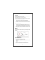
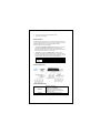
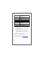
16 Ports Gigabit Switch RGS-1016 User Manual COPYRIGHT & TRADEMARKS Specifications are subject to change without notice. is a registered trademark of Rosewill Inc. Other brands and product names are trademarks or registered trademarks of their respective holders. No part of the specifications may be reproduced in any form or by any means or used to make any derivative such as translation, transformation, or adaptation without permission from Rosewill Inc. Copyright © 2010 Rosewill Inc. All rights reserved. http://www.rosewill.com FCC STATEMENT This equipment has been tested and found to comply with the limits for a Class A digital device, pursuant to part 15 of the FCC Rules. These limits are designed to provide reasonable protection against harmful interference in a residential installation. This equipment generates, uses and can radiate radio frequency energy and, if not installed and used in accordance with the instructions, may cause harmful interference to radio communications. However, there is no guarantee that interference will not occur in a particular installation. If this equipment does cause harmful interference to radio or television reception, which can be determined by turning the equipment off and on, the user is encouraged to try to correct the interference by one or more of the following measures: Reorient or relocate the receiving antenna. Increase the separation between the equipment and receiver. Connect the equipment into an outlet on a circuit different from that to which the receiver is connected. Consult the dealer or an experienced radio/ TV technician for help. This device complies with part 15 of the FCC Rules. Operation is subject to the following two conditions: 1) This device may not cause harmful interference. 2) This device must accept any interference received, including interference that may cause undesired operation. Any changes or modifications not expressly approved by the party responsible for compliance could void the user’s authority to operate the equipment. NOTE: THE MANUFACTURER IS NOT RESPONSIBLE FOR ANY RADIO OR TV INTERFERENCE CAUSED BY UNAUTHORIZED MODIFICATIONS TO THIS EQUIPMENT. SUCH MODIFICATIONS COULD VOID THE USER’S AUTHORITY TO OPERATE THE EQUIPMENT. 2 CE Mark Warning This is a class A product. In a domestic environment, this product may cause radio interference, in which case the user may be required to take adequate measures. Safety Warning Place connecting cables carefully so that no one will step on them or stumble over them. Always disconnect all cables from this device before servicing or disassembling. Use ONLY an appropriate power adaptor or cord for your device. Connect the power adaptor or cord to the right supply voltage (for example, 110V AC in North America or 230V AC in Europe). Do not allow anything to rest on the power adaptor or cord and do not place the product where anyone can walk on the power adaptor or cord. Do not use the device if the power adaptor or cord is damaged as it might cause electrocution. If the power adaptor or cord is damaged, remove it from the power outlet. Do not attempt to repair the power adaptor or cord. Contact your local vendor to order a new one. Do not use the device outside, and make sure all the connections are indoors. Do not obstruct the device ventilation slots, as insufficient airflow may harm your device. Do not use this product near water, eg, in wet basement, or near a swimming pool. Do not expose your device to dampness, dust or corrosive liquids. Do not install, use, or service this device during a thunderstorm. There is a remote risk of electric shock from lightning. Connect ONLY suitable accessories to the device. Do not open the device or unit. Opening or removing covers can expose you to dangerous high voltage points or other risks. ONLY qualified service personnel should service or disassemble this device. Please contact your vendor for further information. Make sure to connect the cables to the correct ports. If you wall mount your device, make sure that no electrical lines, gas or water pipes will be damaged. Your product is marked with this symbol, which is known as the WEEE mark. WEEE stands for Waste Electronics and Electrical Equipment. It means that used electrical and electronic products should not be mixed with general waste. Used electrical and electronic equipment should be treated separately. 3 Package Contents The following contents should be found in your package: One RGS-1016 Switch One power cord This User Guide Rubber footpads Rack-mount kit for installing the switch in a 19-inch rack Note: Make sure that the package contains the above items. If any of the listed items are damaged or missing, please contact with your distributor. Introduction Easily boost your networking throughput, this switch provides you 16 10/100/1000 Mbps gigabit ports that lead you to a real gigabit connection. Users are now able to transfer large and high bandwidth-needed files faster and hence get a real efficiency improvement. The store-and-forward architecture filters errors and forwards packets in a non-blocking environment. Flow control ensures the correctness of data transmitting. The 802.3x and backpressure flow control mechanisms work respectively for full and half duplex modes. The switch features with easy installation and maintenance. It supports NWay auto-negotiation protocol, which detects the networking speed and the duplex modes automatically. Auto-MDI/MDI-X function alleviates the effort to use crossover cables. Users need not to prepare crossover cables for equipment connectivity. It also supports IEEE 802.3az Energy Efficient Ethernet to promise the operation in Low Power Idle Mode and save power consumption. 4 Key Features Supports IEEE 802.3az Energy Efficient Ethernet 16 port auto-sensing 10/100/1000 Mbps Ethernet connections Bandwidth: 32 Gbps (non-blocking) Supports NWay protocol for speed(10/100/1000Mbps) and duplex mode(Half/Full) auto-detection Supports MDI/MDI-X auto crossover and polarity correction Store-and-forward architecture filters fragment & CRC error packets Supports 802.3az Green Ethernet: Detecting port usage power saving and cable length power saving Forward rate (100 Mbps port): 148,800 packet per sec Forward rate (1000 Mbps port): 1,488,000 packet per sec Supports 8K bytes MAC address Queue Buffer Memory: 256 Kbytes Supports 9K bytes jumbo frame 802.1p Quality of Service (QoS) priority support up to 4 queues Acoustic Noise: 0 dB Latency: 1000 to 1000Mbps: Frame size 64 bytes; Latency is 5.4 microsecond (Max.) Frame size 1518 bytes; Latency is 17.2 microsecond (Max.) Integrates 10, 100, & 1000 Mbps devices within a network Delivers up to 2000 Mbps on each port Rack Mount Design Non-blocking Architecture Supports extensive LED indicators for network diagnostics Store-and-forward architecture filters fragment & CRC error packets 5 Front Panel The front panel consists of LED indicators and the ports. 16 Port 19-inch Model Gigabit Ethernet Ports: The switch includes 16 gigabit twisted pair ports, each supporting auto negotiable 10/100/1000 Mbps and auto MDI/MDIX cross over detection functions. This function provides true “plug and play” capability. These ports can operate in half-duplex mode for 10/100 Mbps. LEDs Definition: The switch contains one power LED for the device, Link/Act LEDs for each port that shows the activities and information of the ports. LED Power Link/ ACT Status Operation Steady Green Off Steady Green The switch is powered on The switch is powered off Valid port connection Valid port connection and there is data transmitting/ receiving Port disconnected Blinking Green Off Rear Panel The back panel is shown as bellow (it contains a three pronged receptacle): 16 Port 19-inch Model Power Receptacle To be compatible with the electric service standards around the world, the switch is designed to afford the power supply in the range from 100 to 240VAC, 50/60Hz. Please make sure that your outlet standard to be within this range. To power on the switch, plug the female end of the power cord firmly into the receptacle of the switch and the other end into an electric service outlet. After the power cord installation, please check if the power LED is illuminated for a normal power status. 6 Installation This switch can be mount in the rack or mount on the wall. You can choose the suitable one to install your device. Before installing the switch, we strongly recommend: The switch is placed with appropriate ventilation environment. A minimum 25mm space around the unit is recommended. 1. 2. The switch and the relevant components are away from sources of electrical noise such as radios, transmitters and broadband amplifiers. The switch is away from environments beyond recommend moisture. Wall mount Installation 1. 2. Screw the two provided screws into the wall 150 mm apart horizontally. Leave a small gap between the head of the screw and the wall. The gap should be big enough for the screw heads to slide into the screw slots and the connection cables to run down the back of the switch. Align the holes on the back of the switch with the screws on the wall. Hang the switch on the screws. Warning! Do not wall mount the product vertically or it will be dangerous. Please attach the product on the wall horizontally! See the image below for reference: Rack-mount Installation Procedures to rack-mount the switch in the rack: 1. First disconnect all the cables from the switch. 2. Place the unit the right way up on a hard, flat surface with the front facing you. 3. Locate a mounting bracket over the mounting holes on one side of the unit. 4. Insert the screws and fully tighten with a suitable screwdriver. 5. Repeat the two previous steps for the other side of the unit. 7 6. 7. Insert the unit into the rack with suitable screws Reconnect all the cables. Network Cables In making a switch interconnection, you could use any port to connect another switch with straight or crossover cable. As all the ports support auto MDI / MDI-X function, using a straight cable to make a switch-to-switch connection is allowed. 1. Crossover or straight-through cable: All the ports on the switch support Auto-MDI/MDI-X functionality. Both straight-through or crossover cables can be used to connect the switch with PCs as well as other devices like switches, hubs or router. 2. Category 3, 4, 5, 5e or 6 UTP/STP cable: To make a valid connection and obtain the optimal performance, appropriate cables corresponding to different transmitting/receiving speed is required. To choose a suitable cable, please refer to the following table. Media 10/100/1000 Mbps copper Speed 10Mbps 100Mbps 1000Mbps Wiring Category 3, 4, 5 UTP/STP Category 5 UTP/STP Category 5e, 6 UTP/STP Network Application Product Specifications Standard Interface IEEE802.3 10BASE-T IEEE802.3u 100BASE-TX IEEE802.3ab 1000BASE-T IEEE802.3x full-duplex flow control IEEE802.3az (Energy Efficient Ethernet) IEEE802.1p (QoS) 16x 10/100/1000 Mbps RJ-45 ports 8 Cable Connections Network Data Rate RJ-45 (10BASE-T): Category 3,4,5 UTP/STP RJ-45 (100BASE-TX): Category 5 UTP/STP RJ-45 (1000BASE-T): Category 5e, 6 or enhanced UTP/STP 10/100/1000 Mbps Auto-negotiation 10/100Mbps: Full-duplex, Half-duplex 1000Mbps: Full-duplex System: Power LED Indications Ports: Link/ACT MAC Address Table 8K Buffer Memory 256K bytes Jumbo Frame 9K bytes QoS 802.1p (4 Queues) Operating Temperature: 0~40℃ Operating Temperature Storage Temperature: -10 ~ 70℃ Operating: 10%~90%, non-condensing Operating Humidity Storage: 5% ~ 90%, non-condensing Internal power supply 5V/2A Power Supply 100-240V/50-60 Hz 0.5A, MAX universal input Emission FCC, CE, VCCI Class A Transmission Mode Appendix A: 1. 2. Troubleshooting The Power LED is not lit Make sure the AC power cord connected the Switch with power source properly. Make sure the power source is ON. The Link/Act LED is not lit when a device is connected to the corresponding port Make sure that the cable connectors are firmly plugged into the Switch and the device. Make sure the connected device is turned on and working well. The cable must be less than 100 meters long (328 feet). Thank you for purchasing a quality Rosewill Product. Please register your product at: www.rosewill.com for complete warranty information and future support for your product. Rosewill Customer Service Hotline: 1-800-575-9885 Rosewill Customer Service Support: [email protected] 9