1
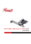
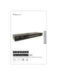
8 Ports Green Gigabit Ethernet PoE/PoE+ Metal Switch RGS-108P User Manual COPYRIGHT & TRADEMARKS Specifications are subject to change without notice. is a registered trademark of Rosewill Inc. Other brands and product names are trademarks or registered trademarks of their respective holders. No part of the specifications may be reproduced in any form or by any means or used to make any derivative such as translation, transformation, or adaptation without permission from Rosewill Inc. Copyright © 2010 Rosewill Inc. All rights reserved. http://www.rosewill.com FCC Certifications This Equipment has been tested and found to comply with the limits for a Class B digital device, pursuant to part 15 of the FCC Rules. These limits are designed to provide reasonable protection against harmful interference when the equipment is operated in a commercial environment. This equipment generates, uses, and can radiate radio frequency energy and, if not installed and used in accordance with the instruction manual, may cause harmful interference to radio communications. Operation of this equipment in a residential area is likely to cause harmful interference in which case the user will be required to correct the interference at his own expense. This device complies with Part 15 of the FCC Rules. Operation is subject to the following two conditions: (1) this device may not cause harmful interference, and (2) this device must accept any interference received; including interference that may cause undesired operation. 2 CE Mark Warning This equipment complies with the requirements relating to electromagnetic compatibility, EN 55022 class B for ITE, the essential protection requirement of Council Directive 2004/108/EC on the approximation of the laws of the Member States relating to electromagnetic compatibility. Company has an on-going policy of upgrading its products and it may be possible that information in this document is not up-to-date. Please check with your local distributors for the latest information. No part of this document can be copied or reproduced in any form without written consent from the company. Trademarks: All trade names and trademarks are the properties of their respective companies. Copyright © 2013, All Rights Reserved. Your product is marked with this symbol, which is known as the WEEE mark. WEEE stands for Waste Electronics and Electrical Equipment. It means that used electrical and electronic products should not be mixed with general waste. Used electrical and electronic equipment should be treated separately. 3 Package Contents The following contents should be found in your package: 8-port Gigabit Ethernet with 2-port PoE+/4-port PoE Desktop Switch 1x AC power cord Rubber feet and screws User’s Manual 2x Brackets 1x Wall mount accessory Note: Make sure that the package contains the above items. If any of the listed items are damaged or missing, please contact with your distributor. Introduction The device is a powerful, high-performance Gigabit Ethernet Switch, with all 8 ports capable of 10/100/1000Mbps auto-negotiation operation (NWay), which means the switch could automatically negotiate with the connected partners on the network speed and duplex mode. It is ideal for micro-segmenting large networks into smaller, connected subnets for improved performance, enabling the bandwidth demanding multimedia and imaging applications. Moreover, the 10/100/1000Mbps auto-sensing ability provides an easy way to migrate 10/100Mbps to 1000Mbps network with no pain. This switch supports PoE (either IEEE802.3at on port 1-2 or IEEE802.3af on port 1-4), which supplies power for connected devices via CAT 5 and above twisted cables. By integrating the data transmitting cable and power cord, it eliminates the effort constructing your network. You could easily connect a Wireless AP or a VoIP phone to this switch without looking outlets for them. Over current protection and circuit shorting protection are also supported to ensure the safety. 4 The switch is plug-n-play without any software to configure and also fully compliant with all kinds of network protocols. Moreover, the rich diagnostic LED indicators on the front-panel provide the operating status of individual port and whole system. Key Features Compliant with IEEE802.3az Energy Efficient Ethernet which allows individual ports to enter a low power idle based on data flow usage. Compliant with IEEE802.1p Fixed LAN Layer 2 QoS/CoS Protocol for Traffic Prioritization for better data transfer management Complies with 10BASE-T specifications of the IEEE802.3 standard Complies with 100BASE-TX specifications of the IEEE802.3u standard Complies with 1000BASE-T specifications of the IEEE802.3ab standard Power over Ethernet (PoE) Standard Compliant with IEEE802.3af or IEEE802.3at (DTE power via MDI): - Supports 4x PoE ports or 2x PoE+ ports (or 1 PoE+ port + 2PoE ports) - 4x PoE ports supports: 802.3af, 15.4W per ports, port 1~4 - 2x PoE+ ports supports: 802.3at, 31.5W per ports, port 1 & 2 - Up to 63W maximum for all PoE Ports (Port 1~4); - Supports PoE Over Current Protection; - Supports PoE Circuit Shorting Protection - Supports PoE Powered Device(PD) classification identify allows to detect power range PoE/PoE+ Full load: Provides 4 PoE ports with classification identify 8x RJ-45 ports for 100BASE-TX and 1000 BASE-T and 10BASE-T connectivity Provide 8x 10/100Mbps auto-detect(half/full) and 1000Mbs full duplex switch ports (IEEE802.3/ 802.3u/ 802.3ab) Supports MDI/MDI-X auto crossover Wire-speed packet filtering and forwarding rate Store-and-forward architecture filters fragment & CRC error packets Supports extensive LED indicators for network diagnostics Internal universal switching power supply PoE+: 31.5W(at) x 2 Ports = 63W ; or PoE: 15.4W(af) x 4 Ports = 61.6W 5 Front Panel The front panel consists of LED indicators and the ports. LEDs Definition The switch contain 1x power LED and 1x Loop Detection LED for the device, 1x PoE LED for each PoE+/PoE port and 1x Link/Act LED for each port. LED indicators for the device The switch provides a power LED and a loop LED for the device. LED Status Operation Steady Green The switch is powered on Off The switch is powered off Blinking Red There is a loop existing Off There is no loop existing Steady Green Valid port connection Blinking Green Valid port connection and there is data transmitting/ receiving Off Port disconnected Green One PoE compliant device is connecting with this port. Off There is no PoE compliant device connecting with this port. Power Loop Link/ ACT PoE The Rear Panel 6 Power Receptacle To be compatible with the electric service standards around the world, the switch is designed to afford the power supply in the range from 100 ~ 240VAC, 50/60Hz. Please make sure that your outlet standard to be within this range. To power on the switch, plug the female end of the power cord firmly into the receptacle of the switch and the other end into an electric service outlet. After the power cord installation, please check if the power LED is illuminated for a normal power status. Installation This switch can be placed on your desktop directly, or mounted in a rack, or mount on wall. The installation is a snap. Users can use all the features of the switch with simply attaching the cables and turning the power on. Before installing the switch, we strongly recommend: 1. The switch is placed with appropriate ventilation environment. a minimum 25mm space around the unit is recommended. 2. The switch and the relevant components are away from sources of electrical noise such as radios, transmitters and broadband amplifiers 3. The switch is away from environments beyond recommend moisture Desktop Installation 1. Install the switch on a level surface that can support the weight of the unit and the relevant components. 2. Plug the switch with the female end of the provided power cord and plug the male end to the power outlet. Wall mount Installation The two slots located on the switch’s bottom panel are for device wall-mount use. The distance between the two slots is 7.8 inches (198.02 mm). Attach two screws on the wall, so that the switch’s wall-mount slots line up with the two screws. Procedures the Wall-Mount to switch: 1. Screw the two provided screws into the wall 150 mm apart horizontally. Leave a small gap between the head of the screw and 7 the wall. The gap should be big enough for the screw heads to slide into the screw slots and the connection cables to run down the back of the switch. 2. Align the holes on the back of the switch with the screws on the wall. Hang the switch on the screws. Rack-mount Installation Rack mounting facilitate to an orderly installation when series of networking devices being installed. The switch is supplied with rack mounting brackets and screws for rack mounting the unit. Procedures to Rack-Mount the Switch in the rack: 1. Disconnect all the cables from the switch before continuing. 2. Place the unit the right way up on a hard, flat surface with the front facing you. 3. Locate a mounting bracket over the mounting holes on one side of the unit. 4. Insert the screws and fully tighten with a suitable screwdriver. 5. Repeat the two previous steps for the other side of the unit. 6. Insert the unit into the rack and secure with suitable screws (not provided). 7. Reconnect all the cables. Network Cables In making a switch interconnection, you could use any port to connect another switch with straight or crossover cable. As all the ports support 8 auto MDI / MDI-X function, using a straight cable to make a switch-to-switch connection is allowed. 1. Crossover or straight-through cable: All the ports on the switch support Auto-MDI/MDI-X functionality. Both straight-through or crossover cables can be used to connect the switch with PCs as well as other devices like switches, hubs or router. 2. Category 3, 4, 5, 5e or 6 UTP/STP cable: To make a valid connection and obtain the optimal performance, appropriate cables corresponding to different transmitting/receiving speed is required. To choose a suitable cable, please refer to the following table. Media Speed Wiring 10 Mbps 10/100/1000 Mbps ports 100 Mbps Category3,4,5 UTP/STP Category 5 UTP/STP 1000 Mbps Category 5e, 6 UTP/STP Ports that support 10/100/1000 Mbps PoE Category5,5e,6 UTP/STP or above Product Specifications IEEE802.3 10BASE-T IEEE802.3u 100BASE-TX IEEE802.3ab 1000BASE-T Standard IEEE 802.3af/at PoE standard (DTE power via MDI) IEEE 802.3az Energy Efficient Ethernet IEEE 802.1p QoS (Fixed LAN Layer 2 QoS/CoS Protocol) IEEE802.3x flow control 8 * 10/100/1000 Mbps auto MDI/MDI-X RJ-45 ports Interface (Port 1~4 support PoE power feeding) (Port 1~2 support PoE+ power feeding) Network Data Rate Transmission Mode 10/100/1000Mbps Auto-negotiation 10/100Mbps: Full-duplex, Half-duplex 1000Mbps Full-duplex 9 LED Indications System: Power,Loop Ports: Link/ACT, PoE 8K MAC address table Memory 9216 bytes jumbo packet length 128K bytes buffer Memory Emission Safety FCC, CE Class B CE EN60950-1 Operating Temperature Operating Humidity Power Supply 00 ~ 400C (320 ~ 1040F) 10% - 90%(non-condensing) 55V 1.36A 100-240V/50-60 Hz universal input Appendix A: 1. Troubleshooting The Power LED is not lit Make sure the AC power cord connected the Switch with power source properly. 2. Make sure the power source is ON. The Link/Act LED is not lit when a device is connected to the corresponding port Make sure that the cable connectors are firmly plugged into the Switch and the device. Make sure the connected device is turned on and working well. The cable must be less than 100 meters long (328 feet). Thank you for purchasing a quality Rosewill Product. Please register your product at: www.rosewill.com for complete warranty information and future support for your product. Rosewill Customer Service Hotline: 1-800-575-9885 Rosewill Customer Service Support: [email protected] 10