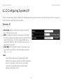
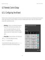
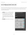
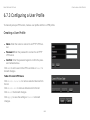
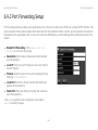
1
® EnGenius EIR900 Wireless-N Dual Band Media Router with Security VPN Support V1.0 TABLE OF CONTENTS TABLE OF CONTENTS Product Overview Product Overview . . . . . . . . . . . . . . . . . . . . . . . . . . . . . . . . . . . . . . . . . . . . . . . . . . . . . . . . . . . . . . . . . . . . . . . . . . . . . . . . . . 1-1 Features . . . . . . . . . . . . . . . . . . . . . . . . . . . . . . . . . . . . . . . . . . . . . . . . . . . . . . . . . . . . . . . . . . . . . . . . . . . . . . . . . . . . 1-2 Package Contents . . . . . . . . . . . . . . . . . . . . . . . . . . . . . . . . . . . . . . . . . . . . . . . . . . . . . . . . . . . . . . . . . . . . . . . . . . . . . . . . . 1-3 Product Layout . . . . . . . . . . . . . . . . . . . . . . . . . . . . . . . . . . . . . . . . . . . . . . . . . . . . . . . . . . . . . . . . . . . . . . . . . . . . . . . . . . . . 1-4 Installation System Requirements . . . . . . . . . . . . . . . . . . . . . . . . . . . . . . . . . . . . . . . . . . . . . . . . . . . . . . . . . . . . . . . . . . . . . . . . . . . . . . 2-1 EnGenius Quick Start Connecting Network Cables. . . . . . . . . . . . . . . . . . . . . . . . . . . . . . . . . . . . . . . . . . . . . . . . . . . . . . . . . . . . . . . . . . . . . . . . . . 3-1 Getting Started . . . . . . . . . . . . . . . . . . . . . . . . . . . . . . . . . . . . . . . . . . . . . . . . . . . . . . . . . . . . . . . . . . . . . . . . . . . . . . . . . . . . 3-4 Setup Notes . . . . . . . . . . . . . . . . . . . . . . . . . . . . . . . . . . . . . . . . . . . . . . . . . . . . . . . . . . . . . . . . . . . . . . . . . . . . . . . . . Accessing the Firmware . . . . . . . . . . . . . . . . . . . . . . . . . . . . . . . . . . . . . . . . . . . . . . . . . . . . . . . . . . . . . . . . . . . . . . . . Accessing the Firmware from a CDROM . . . . . . . . . . . . . . . . . . . . . . . . . . . . . . . . . . . . . . . . . . . . . . . . . . . . . . . . . Accessing the Firmware from a Web Browser . . . . . . . . . . . . . . . . . . . . . . . . . . . . . . . . . . . . . . . . . . . . . . . . . . . . . Logging In. . . . . . . . . . . . . . . . . . . . . . . . . . . . . . . . . . . . . . . . . . . . . . . . . . . . . . . . . . . . . . . . . . . . . . . . . . . . . . . . . 3-4 3-4 3-5 3-6 3-6 Web Configuration Viewing the Dash Board. . . . . . . . . . . . . . . . . . . . . . . . . . . . . . . . . . . . . . . . . . . . . . . . . . . . . . . . . . . . . . . . . . . . . . . . . . . . . 4-1 I TABLE OF CONTENTS Services . . . . . . . . . . . . . . . . . . . . . . . . . . . . . . . . . . . . . . . . . . . . . . . . . . . . . . . . . . . . . . . . . . . . . . . . . . . . . . . . . . . . Home . . . . . . . . . . . . . . . . . . . . . . . . . . . . . . . . . . . . . . . . . . . . . . . . . . . . . . . . . . . . . . . . . . . . . . . . . . . . . . . . . . . . Setup Wizard . . . . . . . . . . . . . . . . . . . . . . . . . . . . . . . . . . . . . . . . . . . . . . . . . . . . . . . . . . . . . . . . . . . . . . . . . . . . . . Network Settings . . . . . . . . . . . . . . . . . . . . . . . . . . . . . . . . . . . . . . . . . . . . . . . . . . . . . . . . . . . . . . . . . . . . . . . . . . . Language . . . . . . . . . . . . . . . . . . . . . . . . . . . . . . . . . . . . . . . . . . . . . . . . . . . . . . . . . . . . . . . . . . . . . . . . . . . . . . . . . Logout . . . . . . . . . . . . . . . . . . . . . . . . . . . . . . . . . . . . . . . . . . . . . . . . . . . . . . . . . . . . . . . . . . . . . . . . . . . . . . . . . . . Web Menus Overview . . . . . . . . . . . . . . . . . . . . . . . . . . . . . . . . . . . . . . . . . . . . . . . . . . . . . . . . . . . . . . . . . . . . . . . . . . . . . . 4-2 4-2 4-2 4-2 4-2 4-2 4-3 System . . . . . . . . . . . . . . . . . . . . . . . . . . . . . . . . . . . . . . . . . . . . . . . . . . . . . . . . . . . . . . . . . . . . . . . . . . . . . . . . . . . . . 4-3 Internet . . . . . . . . . . . . . . . . . . . . . . . . . . . . . . . . . . . . . . . . . . . . . . . . . . . . . . . . . . . . . . . . . . . . . . . . . . . . . . . . . . . . . 4-4 Wireless 2.4G . . . . . . . . . . . . . . . . . . . . . . . . . . . . . . . . . . . . . . . . . . . . . . . . . . . . . . . . . . . . . . . . . . . . . . . . . . . . . . . . 4-5 Wireless 5G. . . . . . . . . . . . . . . . . . . . . . . . . . . . . . . . . . . . . . . . . . . . . . . . . . . . . . . . . . . . . . . . . . . . . . . . . . . . . . . . . . 4-6 Parental Control . . . . . . . . . . . . . . . . . . . . . . . . . . . . . . . . . . . . . . . . . . . . . . . . . . . . . . . . . . . . . . . . . . . . . . . . . . . . . . 4-7 Firewall . . . . . . . . . . . . . . . . . . . . . . . . . . . . . . . . . . . . . . . . . . . . . . . . . . . . . . . . . . . . . . . . . . . . . . . . . . . . . . . . . . . . . 4-8 Virtual Private Network . . . . . . . . . . . . . . . . . . . . . . . . . . . . . . . . . . . . . . . . . . . . . . . . . . . . . . . . . . . . . . . . . . . . . . . . . 4-9 USB Port . . . . . . . . . . . . . . . . . . . . . . . . . . . . . . . . . . . . . . . . . . . . . . . . . . . . . . . . . . . . . . . . . . . . . . . . . . . . . . . . . . . 4-10 Advanced . . . . . . . . . . . . . . . . . . . . . . . . . . . . . . . . . . . . . . . . . . . . . . . . . . . . . . . . . . . . . . . . . . . . . . . . . . . . . . . . . . 4-11 Tools . . . . . . . . . . . . . . . . . . . . . . . . . . . . . . . . . . . . . . . . . . . . . . . . . . . . . . . . . . . . . . . . . . . . . . . . . . . . . . . . . . . . . . 4-12 Installation Setup Wizard Detecting the Internet Connection Type. . . . . . . . . . . . . . . . . . . . . . . . . . . . . . . . . . . . . . . . . . . . . . . . . . . . . . . . . . . . . . . . . 5-1 Basic Network Settings System Setup . . . . . . . . . . . . . . . . . . . . . . . . . . . . . . . . . . . . . . . . . . . . . . . . . . . . . . . . . . . . . . . . . . . . . . . . . . . . . . . . . . . . . 6-1 II TABLE OF CONTENTS Viewing System Status . . . . . . . . . . . . . . . . . . . . . . . . . . . . . . . . . . . . . . . . . . . . . . . . . . . . . . . . . . . . . . . . . . . . . . . . . . . 6-1 System . . . . . . . . . . . . . . . . . . . . . . . . . . . . . . . . . . . . . . . . . . . . . . . . . . . . . . . . . . . . . . . . . . . . . . . . . . . . . . . . . . . . . WAN Settings . . . . . . . . . . . . . . . . . . . . . . . . . . . . . . . . . . . . . . . . . . . . . . . . . . . . . . . . . . . . . . . . . . . . . . . . . . . . . . . . LAN Settings . . . . . . . . . . . . . . . . . . . . . . . . . . . . . . . . . . . . . . . . . . . . . . . . . . . . . . . . . . . . . . . . . . . . . . . . . . . . . . . . . Wireless 2.4G Setting . . . . . . . . . . . . . . . . . . . . . . . . . . . . . . . . . . . . . . . . . . . . . . . . . . . . . . . . . . . . . . . . . . . . . . . . . . Wireless 5G Setting . . . . . . . . . . . . . . . . . . . . . . . . . . . . . . . . . . . . . . . . . . . . . . . . . . . . . . . . . . . . . . . . . . . . . . . . . . . Configuring LAN . . . . . . . . . . . . . . . . . . . . . . . . . . . . . . . . . . . . . . . . . . . . . . . . . . . . . . . . . . . . . . . . . . . . . . . . . . . . . . . . 6-1 6-2 6-3 6-3 6-4 6-5 LAN IP. . . . . . . . . . . . . . . . . . . . . . . . . . . . . . . . . . . . . . . . . . . . . . . . . . . . . . . . . . . . . . . . . . . . . . . . . . . . . . . . . . . . . . DHCP Server . . . . . . . . . . . . . . . . . . . . . . . . . . . . . . . . . . . . . . . . . . . . . . . . . . . . . . . . . . . . . . . . . . . . . . . . . . . . . . . . DNS Server . . . . . . . . . . . . . . . . . . . . . . . . . . . . . . . . . . . . . . . . . . . . . . . . . . . . . . . . . . . . . . . . . . . . . . . . . . . . . . . . . . Configuring DHCP . . . . . . . . . . . . . . . . . . . . . . . . . . . . . . . . . . . . . . . . . . . . . . . . . . . . . . . . . . . . . . . . . . . . . . . . . . . . . . . 6-5 6-6 6-7 6-8 DHCP Client Table . . . . . . . . . . . . . . . . . . . . . . . . . . . . . . . . . . . . . . . . . . . . . . . . . . . . . . . . . . . . . . . . . . . . . . . . . . . . 6-8 Enable Static DHCP IP . . . . . . . . . . . . . . . . . . . . . . . . . . . . . . . . . . . . . . . . . . . . . . . . . . . . . . . . . . . . . . . . . . . . . . . . . 6-9 Current Static DHCP Table . . . . . . . . . . . . . . . . . . . . . . . . . . . . . . . . . . . . . . . . . . . . . . . . . . . . . . . . . . . . . . . . . . . . . . 6-9 Configuring Logging. . . . . . . . . . . . . . . . . . . . . . . . . . . . . . . . . . . . . . . . . . . . . . . . . . . . . . . . . . . . . . . . . . . . . . . . . . . . . 6-10 Log Message List . . . . . . . . . . . . . . . . . . . . . . . . . . . . . . . . . . . . . . . . . . . . . . . . . . . . . . . . . . . . . . . . . . . . . . . . . . . . 6-10 Monitoring Bandwidth Usage. . . . . . . . . . . . . . . . . . . . . . . . . . . . . . . . . . . . . . . . . . . . . . . . . . . . . . . . . . . . . . . . . . . . . . 6-11 Configuring Languages . . . . . . . . . . . . . . . . . . . . . . . . . . . . . . . . . . . . . . . . . . . . . . . . . . . . . . . . . . . . . . . . . . . . . . . . . . 6-12 Configuring WAN Settings . . . . . . . . . . . . . . . . . . . . . . . . . . . . . . . . . . . . . . . . . . . . . . . . . . . . . . . . . . . . . . . . . . . . . . . . . . 6-13 View WAN Status . . . . . . . . . . . . . . . . . . . . . . . . . . . . . . . . . . . . . . . . . . . . . . . . . . . . . . . . . . . . . . . . . . . . . . . . . . . . . . 6-13 WAN Settings . . . . . . . . . . . . . . . . . . . . . . . . . . . . . . . . . . . . . . . . . . . . . . . . . . . . . . . . . . . . . . . . . . . . . . . . . . . . . . . 6-13 Configuring Dynamic IP . . . . . . . . . . . . . . . . . . . . . . . . . . . . . . . . . . . . . . . . . . . . . . . . . . . . . . . . . . . . . . . . . . . . . . . . . . 6-14 III TABLE OF CONTENTS Dynamic IP . . . . . . . . . . . . . . . . . . . . . . . . . . . . . . . . . . . . . . . . . . . . . . . . . . . . . . . . . . . . . . . . . . . . . . . . . . . . . . . . . 6-14 DNS Servers . . . . . . . . . . . . . . . . . . . . . . . . . . . . . . . . . . . . . . . . . . . . . . . . . . . . . . . . . . . . . . . . . . . . . . . . . . . . . 6-15 Configuring Static IP . . . . . . . . . . . . . . . . . . . . . . . . . . . . . . . . . . . . . . . . . . . . . . . . . . . . . . . . . . . . . . . . . . . . . . . . . . . . 6-16 Static IP. . . . . . . . . . . . . . . . . . . . . . . . . . . . . . . . . . . . . . . . . . . . . . . . . . . . . . . . . . . . . . . . . . . . . . . . . . . . . . . . . . . . 6-16 Configuring PPPoE . . . . . . . . . . . . . . . . . . . . . . . . . . . . . . . . . . . . . . . . . . . . . . . . . . . . . . . . . . . . . . . . . . . . . . . . . . . . . 6-17 Configuring PPTP . . . . . . . . . . . . . . . . . . . . . . . . . . . . . . . . . . . . . . . . . . . . . . . . . . . . . . . . . . . . . . . . . . . . . . . . . . . . . . 6-19 WAN Interface Settings. . . . . . . . . . . . . . . . . . . . . . . . . . . . . . . . . . . . . . . . . . . . . . . . . . . . . . . . . . . . . . . . . . . . . . . . Dynamic IP Address . . . . . . . . . . . . . . . . . . . . . . . . . . . . . . . . . . . . . . . . . . . . . . . . . . . . . . . . . . . . . . . . . . . . . . . . Static IP Address . . . . . . . . . . . . . . . . . . . . . . . . . . . . . . . . . . . . . . . . . . . . . . . . . . . . . . . . . . . . . . . . . . . . . . . . . . PPTP Settings. . . . . . . . . . . . . . . . . . . . . . . . . . . . . . . . . . . . . . . . . . . . . . . . . . . . . . . . . . . . . . . . . . . . . . . . . . . . . . . Wireless 2.4G LAN Setup . . . . . . . . . . . . . . . . . . . . . . . . . . . . . . . . . . . . . . . . . . . . . . . . . . . . . . . . . . . . . . . . . . . . . . . . . . 6-19 6-19 6-20 6-21 6-22 Configuring Basic Settings. . . . . . . . . . . . . . . . . . . . . . . . . . . . . . . . . . . . . . . . . . . . . . . . . . . . . . . . . . . . . . . . . . . . . . . . 6-22 Access Point Mode. . . . . . . . . . . . . . . . . . . . . . . . . . . . . . . . . . . . . . . . . . . . . . . . . . . . . . . . . . . . . . . . . . . . . . . . . 6-23 Wireless Distribution System Mode . . . . . . . . . . . . . . . . . . . . . . . . . . . . . . . . . . . . . . . . . . . . . . . . . . . . . . . . . . . . 6-24 Configuring Advanced Settings . . . . . . . . . . . . . . . . . . . . . . . . . . . . . . . . . . . . . . . . . . . . . . . . . . . . . . . . . . . . . . . . . . . . 6-27 Configuring Security . . . . . . . . . . . . . . . . . . . . . . . . . . . . . . . . . . . . . . . . . . . . . . . . . . . . . . . . . . . . . . . . . . . . . . . . . . . . 6-29 Encryption Type . . . . . . . . . . . . . . . . . . . . . . . . . . . . . . . . . . . . . . . . . . . . . . . . . . . . . . . . . . . . . . . . . . . . . . . . . . . . . Wired Equivalent Privacy (WEP) . . . . . . . . . . . . . . . . . . . . . . . . . . . . . . . . . . . . . . . . . . . . . . . . . . . . . . . . . . . . . . Encryption: Wi-Fi Protected Access (WPA) Pre-Shared Key . . . . . . . . . . . . . . . . . . . . . . . . . . . . . . . . . . . . . . . . . . . Encryption: WPA RADIUS . . . . . . . . . . . . . . . . . . . . . . . . . . . . . . . . . . . . . . . . . . . . . . . . . . . . . . . . . . . . . . . . . . . . . Configuring Filter . . . . . . . . . . . . . . . . . . . . . . . . . . . . . . . . . . . . . . . . . . . . . . . . . . . . . . . . . . . . . . . . . . . . . . . . . . . . . . . 6-30 6-30 6-31 6-32 6-33 Enable Wireless Access Control . . . . . . . . . . . . . . . . . . . . . . . . . . . . . . . . . . . . . . . . . . . . . . . . . . . . . . . . . . . . . . . . . 6-33 IV TABLE OF CONTENTS MAC Address Filtering Table . . . . . . . . . . . . . . . . . . . . . . . . . . . . . . . . . . . . . . . . . . . . . . . . . . . . . . . . . . . . . . . . . . . 6-34 Configuring Wi-Fi Protected Setup . . . . . . . . . . . . . . . . . . . . . . . . . . . . . . . . . . . . . . . . . . . . . . . . . . . . . . . . . . . . . . . . . 6-35 Configuring Client List . . . . . . . . . . . . . . . . . . . . . . . . . . . . . . . . . . . . . . . . . . . . . . . . . . . . . . . . . . . . . . . . . . . . . . . . . . . 6-36 Wireless LAN 5G Setup . . . . . . . . . . . . . . . . . . . . . . . . . . . . . . . . . . . . . . . . . . . . . . . . . . . . . . . . . . . . . . . . . . . . . . . . . . . . 6-37 Configuring Basic Settings. . . . . . . . . . . . . . . . . . . . . . . . . . . . . . . . . . . . . . . . . . . . . . . . . . . . . . . . . . . . . . . . . . . . . . . . 6-37 Access Point Mode. . . . . . . . . . . . . . . . . . . . . . . . . . . . . . . . . . . . . . . . . . . . . . . . . . . . . . . . . . . . . . . . . . . . . . . . . 6-38 Wireless Distribution System Mode . . . . . . . . . . . . . . . . . . . . . . . . . . . . . . . . . . . . . . . . . . . . . . . . . . . . . . . . . . . . 6-39 Configuring Advanced Settings . . . . . . . . . . . . . . . . . . . . . . . . . . . . . . . . . . . . . . . . . . . . . . . . . . . . . . . . . . . . . . . . . . . . 6-42 Configuring Security . . . . . . . . . . . . . . . . . . . . . . . . . . . . . . . . . . . . . . . . . . . . . . . . . . . . . . . . . . . . . . . . . . . . . . . . . . . . 6-44 Encryption Type . . . . . . . . . . . . . . . . . . . . . . . . . . . . . . . . . . . . . . . . . . . . . . . . . . . . . . . . . . . . . . . . . . . . . . . . . . . . . Wired Equivalent Privacy (WEP) . . . . . . . . . . . . . . . . . . . . . . . . . . . . . . . . . . . . . . . . . . . . . . . . . . . . . . . . . . . . . . Encryption: Wi-Fi Protected Access (WPA) Pre-Shared Key . . . . . . . . . . . . . . . . . . . . . . . . . . . . . . . . . . . . . . . . . . . Encryption: WPA RADIUS . . . . . . . . . . . . . . . . . . . . . . . . . . . . . . . . . . . . . . . . . . . . . . . . . . . . . . . . . . . . . . . . . . . . . Configuring Filters . . . . . . . . . . . . . . . . . . . . . . . . . . . . . . . . . . . . . . . . . . . . . . . . . . . . . . . . . . . . . . . . . . . . . . . . . . . . . . 6-45 6-45 6-46 6-47 6-48 Enable Wireless Access Control . . . . . . . . . . . . . . . . . . . . . . . . . . . . . . . . . . . . . . . . . . . . . . . . . . . . . . . . . . . . . . . . . 6-48 MAC Address Filtering Table . . . . . . . . . . . . . . . . . . . . . . . . . . . . . . . . . . . . . . . . . . . . . . . . . . . . . . . . . . . . . . . . . . . 6-49 Configuring Wi-Fi Protected Setup . . . . . . . . . . . . . . . . . . . . . . . . . . . . . . . . . . . . . . . . . . . . . . . . . . . . . . . . . . . . . . . . . 6-50 Configuring Client List . . . . . . . . . . . . . . . . . . . . . . . . . . . . . . . . . . . . . . . . . . . . . . . . . . . . . . . . . . . . . . . . . . . . . . . . . . . 6-51 Parental Control Setup . . . . . . . . . . . . . . . . . . . . . . . . . . . . . . . . . . . . . . . . . . . . . . . . . . . . . . . . . . . . . . . . . . . . . . . . . . . . . 6-52 Configuring the Wizard . . . . . . . . . . . . . . . . . . . . . . . . . . . . . . . . . . . . . . . . . . . . . . . . . . . . . . . . . . . . . . . . . . . . . . . . . . 6-52 Configuring the Web Monitor . . . . . . . . . . . . . . . . . . . . . . . . . . . . . . . . . . . . . . . . . . . . . . . . . . . . . . . . . . . . . . . . . . . . . . 6-53 V TABLE OF CONTENTS Firewall Setup. . . . . . . . . . . . . . . . . . . . . . . . . . . . . . . . . . . . . . . . . . . . . . . . . . . . . . . . . . . . . . . . . . . . . . . . . . . . . . . . . . . . 6-54 Configure Basic Settings . . . . . . . . . . . . . . . . . . . . . . . . . . . . . . . . . . . . . . . . . . . . . . . . . . . . . . . . . . . . . . . . . . . . . . . . . 6-54 Configuring Advanced Settings . . . . . . . . . . . . . . . . . . . . . . . . . . . . . . . . . . . . . . . . . . . . . . . . . . . . . . . . . . . . . . . . . . . . 6-55 Configuring Demilitarized Zone . . . . . . . . . . . . . . . . . . . . . . . . . . . . . . . . . . . . . . . . . . . . . . . . . . . . . . . . . . . . . . . . . . . . 6-56 Configuring Denial of Service . . . . . . . . . . . . . . . . . . . . . . . . . . . . . . . . . . . . . . . . . . . . . . . . . . . . . . . . . . . . . . . . . . . . . 6-57 WAN Settings . . . . . . . . . . . . . . . . . . . . . . . . . . . . . . . . . . . . . . . . . . . . . . . . . . . . . . . . . . . . . . . . . . . . . . . . . . . . . . . 6-57 Configuring Access Control Lists. . . . . . . . . . . . . . . . . . . . . . . . . . . . . . . . . . . . . . . . . . . . . . . . . . . . . . . . . . . . . . . . . . . 6-58 Virtual Private Network Setup . . . . . . . . . . . . . . . . . . . . . . . . . . . . . . . . . . . . . . . . . . . . . . . . . . . . . . . . . . . . . . . . . . . . . . . 6-61 Viewing Status . . . . . . . . . . . . . . . . . . . . . . . . . . . . . . . . . . . . . . . . . . . . . . . . . . . . . . . . . . . . . . . . . . . . . . . . . . . . . . . . . 6-61 Configuring a VPN Tunnel Profile . . . . . . . . . . . . . . . . . . . . . . . . . . . . . . . . . . . . . . . . . . . . . . . . . . . . . . . . . . . . . . . . . . 6-63 PPTP. . . . . . . . . . . . . . . . . . . . . . . . . . . . . . . . . . . . . . . . . . . . . . . . . . . . . . . . . . . . . . . . . . . . . . . . . . . . . . . . . . . . . . 6-63 IPSec. . . . . . . . . . . . . . . . . . . . . . . . . . . . . . . . . . . . . . . . . . . . . . . . . . . . . . . . . . . . . . . . . . . . . . . . . . . . . . . . . . . . . . 6-66 Configuring a User Profile . . . . . . . . . . . . . . . . . . . . . . . . . . . . . . . . . . . . . . . . . . . . . . . . . . . . . . . . . . . . . . . . . . . . . . . . 6-69 Creating a User Profile . . . . . . . . . . . . . . . . . . . . . . . . . . . . . . . . . . . . . . . . . . . . . . . . . . . . . . . . . . . . . . . . . . . . . . . . 6-69 Using the Virtual Private Network Wizard . . . . . . . . . . . . . . . . . . . . . . . . . . . . . . . . . . . . . . . . . . . . . . . . . . . . . . . . . . . . 6-70 IPSec. . . . . . . . . . . . . . . . . . . . . . . . . . . . . . . . . . . . . . . . . . . . . . . . . . . . . . . . . . . . . . . . . . . . . . . . . . . . . . . . . . . . . . 6-72 PPTP. . . . . . . . . . . . . . . . . . . . . . . . . . . . . . . . . . . . . . . . . . . . . . . . . . . . . . . . . . . . . . . . . . . . . . . . . . . . . . . . . . . . . . 6-75 USB Port Setup . . . . . . . . . . . . . . . . . . . . . . . . . . . . . . . . . . . . . . . . . . . . . . . . . . . . . . . . . . . . . . . . . . . . . . . . . . . . . . . . . . 6-77 Configuring File Sharing . . . . . . . . . . . . . . . . . . . . . . . . . . . . . . . . . . . . . . . . . . . . . . . . . . . . . . . . . . . . . . . . . . . . . . . . . 6-77 Configuring a File Server . . . . . . . . . . . . . . . . . . . . . . . . . . . . . . . . . . . . . . . . . . . . . . . . . . . . . . . . . . . . . . . . . . . . . . . . . 6-78 Configuring a DNLA Media Server . . . . . . . . . . . . . . . . . . . . . . . . . . . . . . . . . . . . . . . . . . . . . . . . . . . . . . . . . . . . . . . . . 6-79 VI TABLE OF CONTENTS Configuring a Bitorrent Server . . . . . . . . . . . . . . . . . . . . . . . . . . . . . . . . . . . . . . . . . . . . . . . . . . . . . . . . . . . . . . . . . . . . . 6-80 Advanced Network Settings . . . . . . . . . . . . . . . . . . . . . . . . . . . . . . . . . . . . . . . . . . . . . . . . . . . . . . . . . . . . . . . . . . . . . . . . . 6-82 NAT Setup . . . . . . . . . . . . . . . . . . . . . . . . . . . . . . . . . . . . . . . . . . . . . . . . . . . . . . . . . . . . . . . . . . . . . . . . . . . . . . . . . . . . 6-82 Port Mapping Setup . . . . . . . . . . . . . . . . . . . . . . . . . . . . . . . . . . . . . . . . . . . . . . . . . . . . . . . . . . . . . . . . . . . . . . . . . . . . . 6-83 Port Forwarding Setup. . . . . . . . . . . . . . . . . . . . . . . . . . . . . . . . . . . . . . . . . . . . . . . . . . . . . . . . . . . . . . . . . . . . . . . . . . . 6-85 Port Triggering Setup. . . . . . . . . . . . . . . . . . . . . . . . . . . . . . . . . . . . . . . . . . . . . . . . . . . . . . . . . . . . . . . . . . . . . . . . . . . . 6-87 Application Layer Gateway Setup . . . . . . . . . . . . . . . . . . . . . . . . . . . . . . . . . . . . . . . . . . . . . . . . . . . . . . . . . . . . . . . . . . 6-89 Universal Plug and Play Setup . . . . . . . . . . . . . . . . . . . . . . . . . . . . . . . . . . . . . . . . . . . . . . . . . . . . . . . . . . . . . . . . . . . . 6-90 Internet Group Multicast Protocol Setup . . . . . . . . . . . . . . . . . . . . . . . . . . . . . . . . . . . . . . . . . . . . . . . . . . . . . . . . . . . . . 6-91 Quality of Service Setup . . . . . . . . . . . . . . . . . . . . . . . . . . . . . . . . . . . . . . . . . . . . . . . . . . . . . . . . . . . . . . . . . . . . . . . . . 6-92 Priority Queue . . . . . . . . . . . . . . . . . . . . . . . . . . . . . . . . . . . . . . . . . . . . . . . . . . . . . . . . . . . . . . . . . . . . . . . . . . . . . . . 6-93 Bandwidth Allocation. . . . . . . . . . . . . . . . . . . . . . . . . . . . . . . . . . . . . . . . . . . . . . . . . . . . . . . . . . . . . . . . . . . . . . . . . . 6-94 Routing Setup . . . . . . . . . . . . . . . . . . . . . . . . . . . . . . . . . . . . . . . . . . . . . . . . . . . . . . . . . . . . . . . . . . . . . . . . . . . . . . . . . 6-96 NAT Disabled . . . . . . . . . . . . . . . . . . . . . . . . . . . . . . . . . . . . . . . . . . . . . . . . . . . . . . . . . . . . . . . . . . . . . . . . . . . . . . . 6-96 NAT Enabled. . . . . . . . . . . . . . . . . . . . . . . . . . . . . . . . . . . . . . . . . . . . . . . . . . . . . . . . . . . . . . . . . . . . . . . . . . . . . . . . 6-97 Wake on LAN Setup . . . . . . . . . . . . . . . . . . . . . . . . . . . . . . . . . . . . . . . . . . . . . . . . . . . . . . . . . . . . . . . . . . . . . . . . . . . . 6-98 Tools Setup . . . . . . . . . . . . . . . . . . . . . . . . . . . . . . . . . . . . . . . . . . . . . . . . . . . . . . . . . . . . . . . . . . . . . . . . . . . . . . . . . . . . . 6-99 Configuring the Administrator Account . . . . . . . . . . . . . . . . . . . . . . . . . . . . . . . . . . . . . . . . . . . . . . . . . . . . . . . . . . . . . . 6-99 Configuring the Router’s Time . . . . . . . . . . . . . . . . . . . . . . . . . . . . . . . . . . . . . . . . . . . . . . . . . . . . . . . . . . . . . . . . . . . . 6-100 Configuring Dynamic Domain Name Service . . . . . . . . . . . . . . . . . . . . . . . . . . . . . . . . . . . . . . . . . . . . . . . . . . . . . . . . 6-101 Diagnosing a Network Connection . . . . . . . . . . . . . . . . . . . . . . . . . . . . . . . . . . . . . . . . . . . . . . . . . . . . . . . . . . . . . . . . 6-102 VII TABLE OF CONTENTS Upgrading Firmware . . . . . . . . . . . . . . . . . . . . . . . . . . . . . . . . . . . . . . . . . . . . . . . . . . . . . . . . . . . . . . . . . . . . . . . . . . . 6-103 Backing Up Settings . . . . . . . . . . . . . . . . . . . . . . . . . . . . . . . . . . . . . . . . . . . . . . . . . . . . . . . . . . . . . . . . . . . . . . . . . . . 6-104 Rebooting the Device . . . . . . . . . . . . . . . . . . . . . . . . . . . . . . . . . . . . . . . . . . . . . . . . . . . . . . . . . . . . . . . . . . . . . . . . . . 6-105 Appendix A Federal Communication Commission Interference Statement . . . . . . . . . . . . . . . . . . . . . . . . . . . . . . . . . . . . . . . . . . . A-1 Radiation Exposure Statement. . . . . . . . . . . . . . . . . . . . . . . . . . . . . . . . . . . . . . . . . . . . . . . . . . . . . . . . . . . . . . . . . A-2 Appendix B Industry Canada Statement . . . . . . . . . . . . . . . . . . . . . . . . . . . . . . . . . . . . . . . . . . . . . . . . . . . . . . . . . . . . . . . . . . . . . B-1 Appendix C European (CE) Declaration of Conformity. . . . . . . . . . . . . . . . . . . . . . . . . . . . . . . . . . . . . . . . . . . . . . . . . . . . . . . . . . . C-1 Appendix D Link Layers . . . . . . . . . . . . . . . . . . . . . . . . . . . . . . . . . . . . . . . . . . . . . . . . . . . . . . . . . . . . . . . . . . . . . . . . . . . . . . . . . . D-1 Dynamic IP Address (DHCP) . . . . . . . . . . . . . . . . . . . . . . . . . . . . . . . . . . . . . . . . . . . . . . . . . . . . . . . . . . . . . . . . . . . . D-1 Static IP. . . . . . . . . . . . . . . . . . . . . . . . . . . . . . . . . . . . . . . . . . . . . . . . . . . . . . . . . . . . . . . . . . . . . . . . . . . . . . . . . . . . . D-1 Point-to-Point Protocol over Ethernet (PPPoE). . . . . . . . . . . . . . . . . . . . . . . . . . . . . . . . . . . . . . . . . . . . . . . . . . . . . . . D-2 Layer 2 Tunneling Protocol (L2TP) . . . . . . . . . . . . . . . . . . . . . . . . . . . . . . . . . . . . . . . . . . . . . . . . . . . . . . . . . . . . . . . . D-3 Appendix E WorldWide Technical Support. . . . . . . . . . . . . . . . . . . . . . . . . . . . . . . . . . . . . . . . . . . . . . . . . . . . . . . . . . . . . . . . . . . . E-1 VIII CONVENTIONS CONVENTIONS Conventions The following conventions are used to give the user additional information about specific procedures or content. It is important to pay attention to these conventions as they provide information to prevent damage to equipment or personal injury. General Conventions The following general conventions are used in this document. CAUTION! ! CAUTIONS APPEAR BEFORE THE TEXT IT REFERENCES. CAUTIONS APPEAR IN CAPITAL LETTERS TO EMPHASIZE THAT THE ! WARNING! Warning information appears before the text it references to emphasize that the content may prevent damage to the device or equipment. MESSAGE CONTAINS VITAL HEALTH AND SAFETY INFORMATION. Important: Indicates information that is important to know for the proper completion of a procedure, choice of an option, or completing a task. IX CONVENTIONS TYPOGRAPHICAL CONVENTIONS Note: Indicates additional information that is relevant to the current process or procedure. Example: Indicates information used to demonstrate or explain an associated concept. N/A: Indicates that a component or a procedure is not applicable to this model. Prerequisite: Indicates a requirement that must be addressed before proceeding with the current function or procedure. Typographical Conventions The following typographical conventions are used in this document: Italics Indicates book titles, directory names, file names, path names, and program/process names. Constant width Indicates computer output shown on a computer screen, including menus, prompts, responses to input, and error messages. Constant width bold X CONVENTIONS TYPOGRAPHICAL CONVENTIONS Indicates commands lines as entered on the computer. Variables contained within user input are shown in angle brackets (< >). Bold Indicates keyboard keys that are pressed by the user. XI COPYRIGHT COPYRIGHT Copyright This user guide and its content is copyright of © EnGenius Networks, 2011. All rights reserved. Any redistribution or reproduction in part or in whole in any form is prohibited. Do not distribute, transmit, store in any form of electronic retrieval system or commercially exploit the content without the expressed written permission of EnGenius Networks. XII Product Overview PRODUCT OVERVIEW PRODUCT OVERVIEW 1.1 Product Overview The EIR900 combines wired and wireless network access with switching capabilities in a single, affordable device to help enable employees of small businesses like yours safely connect to the resources they need to be productive. It delivers highly secure broadband connectivity, high-speed wire-less networking, and remote access for multiple offices and remote workers. Built for maximum flexibility, it delivers a comprehensive combination of business-class features and ease of use in a scalable solution that is priced for small businesses. Virtual Private Network (VPN) and Enhanced Firewall Protection Strong security features include a proven firewall with intrusion prevention, virtual private network (VPN) capabilities, and an optional service that helps block malicious websites and control web access to protect your business. Unlike standard firewalls, which block incoming streams based only on the source or type of data, the intrusion prevention system scans deep, enabling it to detect and block most worms, Trojan horses, and denial-of-service attacks to help keep your business assets safe. IP Security (IPsec) VPN capabilities built into the EIR900 enable your remote employees, whether working from home or on the road, to connect to your office network using nearly any VPN client to access files and transfer data as securely as if they were in the office. Simultaneous Dual-Band with Advanced Wireless LAN Technology Built for speed, the EIR900 delivers double the bandwidth so you can enjoy the wireless more smoothly, with less lag. Flexible, built-in support for up to 4 multiple service set identifiers (SSIDs) enables the creation separate virtual networks to allow secure guest access and improve traffic flow. 1-1 PRODUCT OVERVIEW FEATURES Sophisticated QoS prioritizes network traffic for demanding voice, video, and data applications. Wi-Fi Protected Setup™ helps make wireless configuration secure and simple Built in Centralized FTP and SAMBA Services EIR900 armed with two USB2.0 port to support SAMBA and FTP File Sharing Services. SAMBA service allows share files with multiple users within office networks without having any technology background, and sharing files by using FTP service with outbound colleagues anytime. Features Dual Band Concurrent support 2.4GHz and 5GHz simultaneously. Gigabit Ethernet connections enable rapid transfer of large files. IPv6 support lets you employ future networking applications and operating systems without costly upgrades. Reliable business-class multifunction router that evolves with your business needs. Secure, high-speed wireless network access for small business. Built-in Storage Link and Media Servers, such as FTP/SAMBA/DLNA/iTunes and BT offline download. 1-2 PRODUCT OVERVIEW PACKAGE CONTENTS 1.2 Package Contents ITEM QUANTITY EIR900 1 12V 3.3A Power Adapter 1 Quick Installation Guide 1 CD Manual 1 RJ-45 Ethernet Cable 1 Device Stand 1 Technical Support Guide 1 Rubber Feet 4 1-3 PRODUCT OVERVIEW PRODUCT LAYOUT 1.3 Product Layout System LED WAN Port WPS Button LAN Ports USB Ports Reset Button DC Power Jack Power Switch 1-4 PRODUCT OVERVIEW PRODUCT LAYOUT FRONT PANEL COMPONENTS WPS Button DESCRIPTION WiFi Protected Setup button To activate WPS, press button for at least 5 seconds. System LED Power status LED. Power Switch Turns the router on or off. DC Power Jack Connects the router to a DC power adapter source. LAN Ports (1 – 4) Connects up to four computers (4) to a local area network (LAN) using Ethernet cable. WAN Port Provides PPPoE, PPTP/L2TP, DHCP/Static IP connectivity to the router from a cable or DSL modem using an Ethernet cable. USB Ports Provides SAMBA/FTP/DLNA/iTunes and BT Offline Download services on connected USB storage. 1-5 Installation INSTALLATION SYSTEM REQUIREMENTS 2.1 System Requirements To install the EIR900, you need the following: Computer (Windows, Linux and MAC OS X Operating Systems) Web Browser (Internet Explorer, FireFox, Chrome, Safari) Network Interface Card with an open RJ-45 Ethernet Port Wi-Fi Card or USB Wi-Fi Dongle (802.11 B/G/N)* External xDSL (ADSL) or Cable Modem with an open RJ-45 Ethernet Port RJ45 Ethernet Cables Note: *Optional 2-1 EnGenius Quick Start ENGENIUS QUICK START CONNECTING NETWORK CABLES 3.1 Connecting Network Cables ! CAUTION! UNPLUG ALL PERIPHERALS AND THE ROUTER ’S ADAPTER BEFORE STARTING WITH THIS PROCEDURE. 1. Connect the adapter cable to an electrical outlet. 3-1 ENGENIUS QUICK START CONNECTING NETWORK CABLES 2. Plug one end of the Ethernet cable (1) into the WAN port on the back panel of the router. Plug the other end of the cable into the cable or DSL modem. Internet 1 3-2 ENGENIUS QUICK START CONNECTING NETWORK CABLES 3. Plug one end of an Ethernet cable (2) into the LAN port on the back panel of the router. Plug the other end of the cable into the Ethernet port of the computer. 1 4. Click Next to display the login screen. See Logging In for more details. Internet 2 Note: If the browser does not show the login screen, enter the default router IP address, 192.168.0.1. Note: Make sure the network cable and power adapter are firmly connected. 3-3 ENGENIUS QUICK START GETTING STARTED 3.2 Getting Started Note: Before getting started power off the cable or DSL modem. Setup Notes When considering the placement of the EIR900 remember the following: It must be located close to a DSL or Cable modem. It must be close to an electrical outlet. Upon first setup, it must be close to the computer that is used to set up and configure the router. For optimal wireless access place the router in the center of the room, at a high altitude and with an unobstructed view of the other wireless devices. Other electronic devices can interfere with the wireless frequency of the router and reduce the wireless access range. Accessing the Firmware There are two ways to access the EIR900 configuration firmware: from a CDROM or a web browser. 3-4 ENGENIUS QUICK START ACCESSING THE FIRMWARE FROM A CDROM Accessing the Firmware from a CDROM Note: If the instructions do not automatically start, open a file manager and browse the root folder of the CD-ROM. Look for the file named index.html and open it. 1. Insert the EIR900 setup CD into the CDROM drive. 2.Click Setup Wizard. The wizard will guide you through setting up your EIR900. 3-5 ENGENIUS QUICK START ACCESSING THE FIRMWARE FROM A WEB BROWSER Accessing the Firmware from a Web Browser 1. Open a web browser. 2. Enter 192.168.0.1 in a web browser URL bar to access the default login screen. Logging In Note: The default user name is admin and the default password is admin. 1. At the login screen enter a user name and a password. 2. Click Login to continue. If the login is successful, the main screen, or dashboard, is displayed. See Viewing the Dash Board for a detailed explanation of the main screen. 3-6 Web Configuration WEB CONFIGURATION VIEWING THE DASH BOARD 4.1 Viewing the Dash Board The main screen, or dashboard, provides access to the router’s main services. Home Setup Wizard Logout Language Network Settings Start the setup wizard. View router information and connection status Set parental control settings. 4-1 WEB CONFIGURATION SERVICES Services The Home, Setup Wizard, Network Settings, Language and Logout links are the main service areas. Home The Home link displays the dashboard screen. Setup Wizard The Setup Wizard link starts the wizard that automatically configures the router. See Detecting the Internet Connection Type. Network Settings The Network Settings link displays the menus to manually configure the router. See Web Menus Overview. Language The Language link displays the menu to set the OSD language. See Configuring Languages. Logout The Logout link closes the router configuration software. 4-2 WEB CONFIGURATION WEB MENUS OVERVIEW 4.2 Web Menus Overview System View and edit settings that affect system functionality. Status Display the summary of the current system status. LAN Configure the wired network. DHCP Configure dynamically allocated IP addresses. Log View recorded system operations and network activity events. Monitor View the current network traffic bandwidth usage. Language Configure the application menu and GUI language. 4-3 WEB CONFIGURATION INTERNET Internet View and edit settings that affect network connectivity. Status Display the summary of the Internet status and type of connection. Dynamic IP Setup a dynamic IP connection to an Internet service provider (ISP). Static IP Setup a static IP connection to an ISP. PPPoE Setup a PPPoE connection to an ISP. PPTP Setup a PPTP connection to an ISP. 4-4 WEB CONFIGURATION WIRELESS 2.4G Wireless 2.4G View and edit settings for 2.4G wireless network connectivity. Basic Configure the minimum settings required to setup a wireless network connection. Advanced Configure the advanced network settings. Security Configure the wireless network security settings. Filter Configure a list of clients that are allowed to wirelessly connect to the network. WPS Automate the connection between the a wireless device and the router using an 8digit PIN. Client List View the 2.4G wireless devices currently connected to the network. 4-5 WEB CONFIGURATION WIRELESS 5G Wireless 5G View and edit settings for 5G wireless network connectivity. Basic Configure the minimum settings required to setup a wireless network connection. Advanced Configure the advanced network settings. Security Configure the wireless network security settings. Filter Configure a list of clients that are allowed to wirelessly connect to the network. WPS Automate the connection between the a wireless device and the router using an 8digit PIN. Client List View the 5G wireless devices currently connected to the network. 4-6 WEB CONFIGURATION PARENTAL CONTROL Parental Control View and configure settings for parental control policies. Wizard Automatically configure access to the LAN and WAN. Web Monitor Monitor and filter access to specified URLs. 4-7 WEB CONFIGURATION FIREWALL Firewall View and configure settings for firewall rule sets. Basic Enable or disable the network firewall. Advanced Configure virtual private network (VPN) packets. DMZ Redirect packets from the WAN port IP address to a particular IP address on the LAN. DoS Enable or disable blocking of denial of service (DoS) attacks. ACL Create access control lists to specified URLs. 4-8 WEB CONFIGURATION VIRTUAL PRIVATE NETWORK Virtual Private Network View and configure settings for VPN tunnelling. Status View the status of current VPN tunnels. Profile Setting Manually configure VPN tunnels. User Setting Configure users, user ID and password combinations, and assign access to specific VPN tunnels. Wizard Automatically configure VPN tunnels with guidance from the software. 4-9 WEB CONFIGURATION USB PORT USB Port View and configure settings for USB ports. File Sharing Enable or disable the file sharing service. File Server Enable and configure an FTP server. DNLA Enable and configure a DNLA media server. Bitorrent Server Enable or disable a bitorrent server. 4-10 WEB CONFIGURATION ADVANCED Advanced View and configure advanced system and network settings. NAT Enable or disable Network Address Translation (NAT). Port Mapping Re-direct a range of service port numbers to a specified LAN IP address. Port Forwarding Configure server applications to send and receive data from specific ports on the network. Port Triggering Configure applications that require multiple connections and different inbound and outbound connections. ALG Configure the application layer gateway (ALG). UPnP Enable or disable Universal Plug and Play (UPnP) functionality. IGMP Enable or disable the Internet Group Multicast Protocol (IGMP). QoS Configure the network quality of service (QoS) setting by prioritizing the uplink and downlink bandwidth. Routing Configure static routing. WOL Configure wake on LAN (WOL) to turn on a computer over the network. 4-11 WEB CONFIGURATION TOOLS Tools View and configure system and network tools settings. Admin Configure the administrator password used to login to the router. Time Configure the system time on the router. DDNS Map a static domain name to a dynamic IP address. Diagnosis Check if a specific computer is connected to the LAN. Firmware Update the router’s firmware. Backup Load or save configuration settings from a backup file or restore the factory default settings. Reset Manually reset the router. 4-12 Installation Setup Wizard INSTALLATION SETUP WIZARD DETECTING THE INTERNET CONNECTION TYPE 5.1 Detecting the Internet Connection Type Use the Wizard to automatically detect the type of Internet connection. Note: See Logging In for details on how to view the dashboard. 1. Click Wizard to start the detection process. 5-1 INSTALLATION SETUP WIZARD DETECTING THE INTERNET CONNECTION TYPE 2. Click Next to continue or Cancel to cancel the wizard. 5-2 INSTALLATION SETUP WIZARD DETECTING THE INTERNET CONNECTION TYPE 3. The Wizard displays a progress bar while detecting the type of Internet connection. Note: This process may take several seconds. Progress Bar 5-3 INSTALLATION SETUP WIZARD DETECTING THE INTERNET CONNECTION TYPE 4. If the EIR900 can not detect the type of Internet connection, the following screen is displayed. 5. Select a login method from the dropdown list. 5-4 INSTALLATION SETUP WIZARD DETECTING THE INTERNET CONNECTION TYPE 6. Fill in the required information. Note: There are four methods available to connect to the Internet: DHCP, Static IP, PPPoE and PPTP. For a description of each method, refer to Link Layers. For configuration instructions, refer to Configuring Dynamic IP, Configuring Static IP, Configuring PPPoE or Configuring PPTP. 7. Click Next to save these settings and continue to the next step; click Rescan to detect the Internet connection method; click Skip to discard changes and continue to the next step. 5-5 INSTALLATION SETUP WIZARD DETECTING THE INTERNET CONNECTION TYPE 8. For the Wireless 2.4G connection, in the SSID text field enter a router name and in the Key text field enter a password. ! WARNING! Select High as the security level to best secure the wireless network. 5-6 INSTALLATION SETUP WIZARD DETECTING THE INTERNET CONNECTION TYPE 9. For the Wireless 5G connection, in the SSID text field enter a router name and in the Key text field enter a password. ! WARNING! Select High as the security level to best secure the wireless network. 10.Click Next to save these settings or click Skip to discard changes and continue to the next step. 5-7 INSTALLATION SETUP WIZARD DETECTING THE INTERNET CONNECTION TYPE 11.Review the settings. 12. Click Apply to save the information entered in the previous steps. The EIR900 setup is complete. 5-8 Basic Network Settings BASIC NETWORK SETTINGS SYSTEM SETUP 6.1 System Setup 6.1.1 Viewing System Status The status page shows the summary of the current system status including system (hardware/software version, date/time), Internet connection (WAN), wired network (LAN) and wireless network (WLAN) information. System Model The model name of the EIR900. Mode The router’s operating mode (AP / Router / WDS). Uptime The amount of time the device has been active. Current Date/Time The current system date and time. Hardware Version The hardware version number of the EIR900. Serial Number The serial number of the EIR900. The serial number is required for customer service or support. Application Version The firmware version number of the EIR900. Note: To update the firmware visit www.engeniusnetworks.com. 6-1 BASIC NETWORK SETTINGS WAN SETTINGS WAN Settings Attain IP Protocol Displays the IP protocol in use for the EIR900. It can be a dynamic or static IP address. IP Address The router’s IP address as designated by an ISP provider. Subnet Mask The router’s WAN subnet mask as designated by an ISP provider. Default Gateway The router’s gateway address as designated by an ISP provider. MAC Address The router’s WAN MAC address. The router’s MAC address is located on the label on the back side of the router. Primary DNS The primary DNS of an ISP provider. Secondary DNS The secondary DNS of an ISP provider. 6-2 BASIC NETWORK SETTINGS LAN SETTINGS LAN Settings IP Address The router’s local IP address. The default LAN IP address is 192.168.0.1. Subnet Mask The router’s local subnet mask. DHCP Server: The DHCP setting status (Default: Enabled). MAC Address The router’s LAN MAC address. Wireless 2.4G Setting Channel The communications channel used by all stations, or computing devices, on the network. ESSID The ID value of a set of one or more interconnected basic service sets (BSSs). Security The security setting status (Default: Disabled). BSSID The unique ID of the BSS using the above channel value on this router. The ID is the MAC address of the BSSs access point. Associated Clients The number of clients associated with this SSID. 6-3 BASIC NETWORK SETTINGS WIRELESS 5G SETTING Wireless 5G Setting Channel The communications channel used by all stations, or computing devices, on the network. ESSID The ID value of a set of one or more interconnected basic service sets (BSSs). Security The security setting status (Default: Disabled). BSSID The unique ID of the BSS using the above channel value on this router. The ID is the MAC address of the BSSs access point. Associated Clients The number of clients associated with this SSID. 6-4 BASIC NETWORK SETTINGS CONFIGURING LAN 6.1.2 Configuring LAN Configure the wired network settings in the LAN section. The router’s IP is defined in the IP Address field. The default setting of the DHCP server is set to enabled so that network clients can be automatically assigned a virtual IP addresses. Advanced users may configure DNS server settings to meet specific requirements. Changing the settings in this section are not necessary for most situations. Note: Keep the default values if you are uncertain of the settings values. LAN IP \ IP Address Configure the router’s LAN IP address. IP Subnet Mask Configure the router’s LAN Subnet Mask 802.1d Spanning Tree The 802.1d Spanning Tree settings is disabled by default. When enabled, the spanning tree protocol is applied to prevent network loops (transmissions won’t pass the same node twice to reach the destination). 6-5 BASIC NETWORK SETTINGS DHCP SERVER DHCP Server The DHCP server assigns IP addresses to the devices on the LAN. DHCP Server Enable or disable the DHCP server (Default: Enabled). Lease Time Configure the amount of time each allocated IP address can by used by a client. Start IP The first IP address in the range of addresses assigned by the router. End IP The last IP address in the range of addresses assigned by the router. Domain Name: The domain name of the router. 6-6 BASIC NETWORK SETTINGS DNS SERVER DNS Server The domain name system (DNS) server translates a domain or website name into a uniform resource locator (URL), or Internet address. There are four options to choose from: From ISP, User-Defined, DNS Relay or None. Select From ISP to retrieve the DNS address value from the ISP; select User-Defined to assign a custom DNS server address; select DNS Relay to forward all queries to a relay, which in turn sends them to an ISP’s DNS server; select None to assign no server. First DNS Server Configure the first, or primary, DNS server. (Default = DNS Relay) Second DNS Server Configure the second, or secondary, DNS server. (Default = None) Click Apply to save the settings. 6-7 BASIC NETWORK SETTINGS CONFIGURING DHCP 6.1.3 Configuring DHCP View active dynamically allocated IP (DHCP) addresses and configure and view static DHCP IP addresses. ! WARNING! Do not modify the settings in this section without a thorough understanding of the parameters. DHCP Client Table Displays the connected DHCP clients whose IP addresses are assigned by the DHCP server on the LAN. Click Refresh to update the table. 6-8 BASIC NETWORK SETTINGS ENABLE STATIC DHCP IP Enable Static DHCP IP Click Enable Static DHCP IP to add more static DHCP IP addresses. Click Reset to return the table to its previous state. Current Static DHCP Table Active static DHCP addresses are listed along with the associated MAC addresses. Click Delete Selected to remove a selected address. Click Delete All to remove all addresses from the table. Click Reset to return the table to its previous state. Click Apply to save the settings. 6-9 BASIC NETWORK SETTINGS CONFIGURING LOGGING 6.1.4 Configuring Logging The logging service records and displays important system information and activity on the network. The events are stored in a memory buffer with older data overwritten by newer when the buffer is full. Log Message List Shows the current system operations and network activity. Click Save to store data to a log file. Click Clear to empty the log file. Click Refresh to empty the log file and begin updating it with new data. 6-10 BASIC NETWORK SETTINGS MONITORING BANDWIDTH USAGE 6.1.5 Monitoring Bandwidth Usage View bandwidth usage for LAN and WLAN traffic. Displays the bandwidth usage for the WLAN and LAN networks. 6-11 BASIC NETWORK SETTINGS CONFIGURING LANGUAGES 6.1.6 Configuring Languages The router supports multiple languages for using the graphical user interface (GUI). Select the language to use from the dropdown list. 6-12 BASIC NETWORK SETTINGS CONFIGURING WAN SETTINGS 6.2 Configuring WAN Settings 6.2.1 View WAN Status The WAN Settings, or Internet Status, page shows a summary of the current Internet connection information. This section is also shown on the System Status page. WAN Settings Attain IP Protocol Display the IP Protocol type used for the EIR900 (Dynamic IP Address or Static IP Address). IP Address The router’s WAN IP address. Subnet Mask The router’s WAN subnet mask. Default Gateway The ISP’s gateway IP address. MAC Address The router’s WAN MAC address. The router’s MAC address is located on the label on the back side of the router. Primary DNS The primary DNS address of an ISP provider. Secondary DNS: The secondary DNS address of an ISP provider. 6-13 BASIC NETWORK SETTINGS CONFIGURING DYNAMIC IP 6.2.2 Configuring Dynamic IP Dynamic IP addressing assigns a different IP address each time a device connects to an ISP service provider. The service is most commonly used by ISP cable providers. Dynamic IP Host name Assign a name for the internet connection type. This field can be blank. MTU Configure the maximum transmission unit (MTU). The MTU specifies the largest packet size permitted for an internet transmission. The factory default MTU size for Dynamic IP (DHCP) is 1500. The MTU size can be set between 512 and 1500. Clone MAC Enter the MAC address of the devices’ network interface card (NIC) in the MAC address field and click Clone MAC. Note: Some ISP providers require registering the MAC address of the network interface card (NIC) connected directly to the cable or DSL modem. Clone MAC masks the router's MAC address with the MAC address of the device’s NIC. 6-14 BASIC NETWORK SETTINGS DNS SERVERS DNS Servers The DNS server translates a domain or website name into a uniform resource locator (URL), or Internet address. There are two options to choose from: From ISP or User-Defined. Select From ISP to retrieve the DNS address value from the ISP; select User-Defined to assign a custom DNS server address. DNS Server Configure the type of DNS server. (Default = From ISP) First DNS Server Configure the first, or primary, DNS server. Second DNS Server: Configure the second, or secondary, DNS server. Click Apply to save the settings. 6-15 BASIC NETWORK SETTINGS CONFIGURING STATIC IP 6.2.3 Configuring Static IP Setting a static IP address allows an administrator to set a specific IP address for the router and guarantees that it can not be assigned a different address. Static IP IP Address The router’s WAN IP address. Subnet Mask The router’s WAN subnet mask. Default Gateway The router’s gateway address. Primary DNS The primary DNS server address. Secondary DNS The secondary DNS server address. MTU The maximum transmission unit (MTU) specifies the largest packet size permitted for an internet transmission. The factory default MTU size for static IP is 1500. The MTU size can be set between 512 and 1500. Click Apply to save the settings. 6-16 BASIC NETWORK SETTINGS CONFIGURING PPPOE 6.2.4 Configuring PPPoE Point-to-Point Protocol over Ethernet (PPPoE) is used mainly by ISPs that provide DSL modems to connect to the Internet. Login Enter the username assigned by an ISP. Password Enter the password assigned by an ISP. Service Name Enter the service name of an ISP (optional). MTU Enter the maximum transmission unit (MTU). The MTU specifies the largest packet size permitted for an internet transmission (PPPoE default: 1492). The MTU size can be set between 512 and 1492. Authentication Type Select the type of authentication provided by the ISP: Auto, PAP, or CHAP. If unsure of the best setting, select Auto. 6-17 BASIC NETWORK SETTINGS CONFIGURING PPPOE Type Configure the connection type between the router and the ISP. Choose between Keep Connection, Automatic Connection or Manual Connection. Idle Timeout Configure the maximum idle time (1 to 1,000 minutes) allowed for an inactive connection. Clone MAC Enter the MAC address of the devices’ network interface card (NIC) in the MAC address field and click Clone MAC. Note: Some ISP providers require registering the MAC address of the network interface card (NIC) connected directly to the cable or DSL modem. Clone MAC masks the router's MAC address with the MAC address of the device’s NIC. Click Apply to save the settings or Cancel to discard the changes. 6-18 BASIC NETWORK SETTINGS CONFIGURING PPTP 6.2.5 Configuring PPTP The point-to-point tunnelling protocol (PPTP) is used in association with virtual private networks (VPNs). There a two parts to a PPTP connection: the WAN interface settings and the PPTP settings. WAN Interface Settings Dynamic IP Address WAN Interface Type Select Dynamic IP Address to assign an IP address provided by an ISP. Hostname Enter a host name of an ISP. (optional). Clone MAC Enter the MAC address of the devices’ network interface card (NIC) in the MAC address field and click Clone MAC. Note: Some ISP providers require registering the MAC address of the network interface card (NIC) connected directly to the cable or DSL modem. Clone MAC masks the router's MAC address with the MAC address of the device’s NIC. 6-19 BASIC NETWORK SETTINGS STATIC IP ADDRESS Static IP Address WAN Interface Type Select Static IP Address to assign a specific IP address for the router. My IP Address Enter the custom IP address. My Subnet Mask Enter the custom subnet mask. Gateway IP Address Enter the custom gateway IP address. 6-20 BASIC NETWORK SETTINGS PPTP SETTINGS PPTP Settings User Name Enter the username assigned by your ISP. Password: Enter the password assigned by your ISP. Service IP Address: Enter the PPTP server IP address provided by your ISP. Connection ID: Enter the connection ID provided by your ISP (optional). MTU Enter the maximum transmission unit (MTU). The MTU specifies the largest packet size (Default: 1462) permitted for an internet transmission. The MTU size can be set between 512 and 1492. Type Configure the connection type between the router and the ISP. Choose between Keep Connection, Automatic Connection or Manual Connection. Idle Timeout Configure the maximum amount of time, in minutes, allowed for inactive Internet connection. The Internet connection will be dropped when the maximum idle time is reached. Valid values are between one and one thousand. Click Apply to save the settings or Cancel to discard the changes. 6-21 BASIC NETWORK SETTINGS WIRELESS 2.4G LAN SETUP 6.3 Wireless 2.4G LAN Setup 6.3.1 Configuring Basic Settings Radio Enable or disable the wireless radio. If the wireless radio is disabled, wireless access points are not available. Mode Select the wireless operating mode for the router. Two modes are available: Access Point or Wireless Distribution System (WDS) mode. AP Provides a connection access point for wireless devices. WDS Allows the wireless network to be expanded using multiple access points without wired connections. 6-22 BASIC NETWORK SETTINGS ACCESS POINT MODE Access Point Mode Configure the wireless settings of the router in access point mode. Band: Select a wireless standard for the network from the following options: 2.4 GHz (B) 2.4 GHz (G) 2.4 GHz (N) 2.4 GHz (B+G) 2.4 GHz (B+G+N) Enable SSID# Select the number of wireless groups, between one and four, available on the network. SSID[#] Enter the name of the wireless network(s). Auto Channel Enable or disable having the router automatically select a channel for the wireless network. Auto channel is enabled by default. Select disable to manually assign a specific channel. (Default = Disable) Check Channel Time When auto channel is enabled, select time period that the system checks the appropriate channel for the router. 6-23 BASIC NETWORK SETTINGS WIRELESS DISTRIBUTION SYSTEM MODE Channel When auto channel is disabled, select a channel to assign to the wireless network. Valid value are from one to eleven in the US and one to thirteen in the EU. Wireless Distribution System Mode Configure the router’s wireless settings in WDS mode. Channel Select a channel to assign to the wireless network. Valid value are from one to eleven in the US and one to thirteen in the EU. MAC Address [#] Enter the MAC address(es) for the wireless access point(s) that are part of the WDS. WDS Data Rate Select the data rate for the WDS. Set Security Click Set Security to display the WDS security settings screen. For security configuration settings, refer to “WDS Security Settings Screen” on page 625.. Click Apply to save the settings or Cancel to discard changes. 6-24 BASIC NETWORK SETTINGS WIRELESS DISTRIBUTION SYSTEM MODE WDS Security Settings Screen Select the type of WDS encryption (Disable, WEP or WPA Pre-Shared Key) for the wireless network. Wired Equivalent Privacy (WEP) Key Length Select between 64-bit and 128-encryption. Key Format Select the type of characters used for the WEP Key: ASCII (5 characters) or Hexadecimal (10 characters). Default Key Select the default encryption key for wireless transactions. Encryption Key [#] Enter the encryption key(s) used to encrypt the data packets during data transmission. Click Apply to save the settings or Cancel to discard changes. 6-25 BASIC NETWORK SETTINGS WIRELESS DISTRIBUTION SYSTEM MODE Wi-Fi Protected Access (WPA) Pre-Shared Key WPA Type Select the type of WPA. WPA Temporal Key Integrity Protocol (TKIP) Generates a 128-bit key for each packet. WPA2 Advanced Encryption Standard (AES) Government standard packet encryption which is stronger than TKIP. WPA2 Mixed Mixed mode allows device to try WPA2 first, and if that fails selects WPA type. Pre-Shared Key Type Select the type of pre-shared key as Passphrase (ASCII) or Hexadecimal. Pre-Shared Key Enter the pre-shared Key value. Click Apply to save the settings or Cancel to discard changes. 6-26 BASIC NETWORK SETTINGS CONFIGURING ADVANCED SETTINGS 6.3.2 Configuring Advanced Settings Advanced settings parameters available on the router. ! WARNING! Incorrectly changing these settings may cause the device to stop functioning. Do not modify the settings in this section without a thorough understanding of the parameters. Fragment Threshold Enter the maximum size of a packet during data transmission. A value too low could lead to low performance. RTS Threshold Enter the RTS threshold. If the packet size is smaller than the RTS threshold, the EIR900 does not use RTS/CTS to send the data packet. Beacon Interval Enter the beacon interval. This is the amount of time that the EIR900 sets to synchronize the network. Delivery Traffic Indication Message (DTIM) Period Enter the DTIM period. The DTIM is a countdown period informing clients of the next point of broadcast and multicast of messages over the network. Valid values are between 1 and 255. 6-27 BASIC NETWORK SETTINGS CONFIGURING ADVANCED SETTINGS N Data Rate Select the N data rate. This is the rate in which the EIR900 will transmit data packets to wireless N compatible devices. Channel Bandwidth Select the channel bandwidth. The factory default is Auto 20/40MHz. The default setting provides the best performance by auto selecting channel bandwidth. Preamble Type Select the preamble type. Long Preamble provides better LAN compatibility and Short Preamble provides better wireless performance. CTS Protection Select the type of CTS protection. Using CTS Protection can lower the data collisions between Wireless B and Wireless G devices and lower data throughput. Tx Power Select the wireless signal strength level. Valid values are between 10% and 100%. Click Apply to save the settings or Cancel to discard changes. 6-28 BASIC NETWORK SETTINGS CONFIGURING SECURITY 6.3.3 Configuring Security Enable security options on the wireless network to prevent intrusions to systems on the wireless network. SSID Selection Select the wireless network group to change the wireless security settings for. Broadcast SSID Enable or disable broadcast SSID. Choose whether or not the wireless group is visible to other members. Wi-Fi Multimedia (WMM) Enable or disable quality of server (QoS) to optimize the streaming for bandwidth sensitive data such as HDTV video streaming, online gaming, VoIP, videoconferencing, and etc. Encryption Select the encrypt type for the router. Click Apply to save the settings. 6-29 BASIC NETWORK SETTINGS ENCRYPTION TYPE Encryption Type Wired Equivalent Privacy (WEP) Authentication Type Select the type of authentication. Open System Wireless stations can associate with the EIR900 without WEP encryption Shared Key Devices must provide the corresponding WEP key(s) when connecting to the EIR900. Auto Key Length Select between 64-bit and 128-encryption. Key Type Select the type of characters used for the WEP Key: ASCII (5 characters) or Hexadecimal (10 characters). Encryption Key [#] Enter the encryption key(s) used to encrypt the data packets during data transmission. Click Apply to save the settings. 6-30 BASIC NETWORK SETTINGS ENCRYPTION: WI-FI PROTECTED ACCESS (WPA) PRE-SHARED KEY Encryption: Wi-Fi Protected Access (WPA) Pre-Shared Key WPA Type Select the type of WPA. WPA Temporal Key Integrity Protocol (TKIP) Generates a 128-bit key for each packet. WPA2 Advanced Encryption Standard (AES) Government standard packet encryption which is stronger than TKIP. WPA2 Mixed Mixed mode allows device to try WPA2 first, and if that fails selects WPA type. Pre-Shared Key Type Select the type of pre-shared key as Passphrase (ASCII) or Hexadecimal. Pre-Shared Key Enter the pre-shared Key value. Click Apply to save the settings. 6-31 BASIC NETWORK SETTINGS ENCRYPTION: WPA RADIUS Encryption: WPA RADIUS Use a RADIUS server to authenticate wireless stations and provide a session key to encrypt data during communications. WPA Type Select the type of Wireless Protected Access (WPA). WPA Temporal Key Integrity Protocol (TKIP) Generates a 128-bit key for each packet. WPA2 Advanced Encryption Standard (AES) Protects unauthorized access by verifying network users (encryption is stronger than TKIP). WPA2 Mixed Mixed mode allows device to try WPA2 first, and if that fails selects WPA type. RADIUS Server IP Address: Enter the IP address of the server. RADIUS Server Port: Enter the port number of the server. RADIUS Server Password: Enter the password of the server. Click Apply to save the settings or Cancel to discard changes. 6-32 BASIC NETWORK SETTINGS CONFIGURING FILTER 6.3.4 Configuring Filter ! WARNING! Incorrectly changing these settings may cause the device to stop functioning. Do not modify the settings in this section without a thorough understanding of the parameters. When Enable Wireless Access Control is selected, only wireless clients with MAC addresses listed in the table are allowed to connect to the wireless network. Enable Wireless Access Control Description Enter a description of the device allowed to connect to the network. MAC Address Enter the MAC address of the wireless device. Click Add to append a new device to the list or Reset to discard changes. 6-33 BASIC NETWORK SETTINGS MAC ADDRESS FILTERING TABLE MAC Address Filtering Table No. The sequence number of the device. Description The description of the device. MAC Address The MAC address of the device. Select Indicates the device(s) that can have actions performed on them. Click Delete Selected to remove selected devices from the list. Click Delete All to remove all devices form the list. Click Reset the discard changes. Click Apply to save the settings or Cancel to discard changes. 6-34 BASIC NETWORK SETTINGS CONFIGURING WI-FI PROTECTED SETUP 6.3.5 Configuring Wi-Fi Protected Setup Wi-Fi protected setup (WPS) is an easy way to allow wireless clients to connect to the EIR900. Automate the connection between the device and the EIR900 using a button or a PIN. WPS Enable or disable WPS. WPS Current Status A notification of whether or not wireless security is configured. Self Pin Code An 8-digit PIN which is required when configuring the router for the first time in Windows 7 or Vista. SSID The name of the wireless network. Authentication Mode The current security settings for the corresponding SSID. Passphrase Key A randomly generated key created by the EIR900 during WPS. WPS via Push Button Click Start to Process to activate WPS. WPS via PIN Enter the PIN of a wireless device click Start to Process to activate WPS. 6-35 BASIC NETWORK SETTINGS CONFIGURING CLIENT LIST 6.3.6 Configuring Client List View the 2.4G wireless devices currently connected to the EIR900. Interface The type of network connected to the device. MAC Address The MAC address of device connected to network. Signal The signal strength of the device connected to the network. Idle Time The amount of time the connected device has not been active on the network. Click Refresh to refill the list with currently connected devices. 6-36 BASIC NETWORK SETTINGS WIRELESS LAN 5G SETUP 6.4 Wireless LAN 5G Setup 6.4.1 Configuring Basic Settings Radio Enable or disable the wireless radio. If the wireless radio is disabled, wireless access points are not available. Mode Select the wireless operating mode for the router. Two modes are available: Access Point or Wireless Distribution System (WDS) mode. AP Provides an access point for wireless devices to connect to. WDS Access points expand the wireless coverage area by connecting to each other and acting as one. 6-37 BASIC NETWORK SETTINGS ACCESS POINT MODE Access Point Mode Configure the wireless settings of the router in access point mode. Band: Select a wireless standard for the network from the following options: 5 GHz (802.11 a) 5 GHz (802.11 n) 5 GHz (802.11 a/n) Enable SSID# Select the number of wireless groups, between one and four, available on the network. SSID[#] Enter the name of the wireless network(s). Auto Channel Enable or disable having the router automatically select a channel for the wireless network. Auto channel is enabled by default. Select disable to manually assign a specific channel. (Default = Disable) Check Channel Time When auto channel is enabled, select time period that the system checks the appropriate channel for the router. Channel When auto channel is disabled, select a channel to assign to the wireless network. 6-38 BASIC NETWORK SETTINGS WIRELESS DISTRIBUTION SYSTEM MODE Wireless Distribution System Mode Configure the wireless settings of the router in WDS mode. Channel Select a channel to assign to the wireless network. MAC Address [#] Enter the MAC address(es) for the wireless access point(s) that are part of the WDS. WDS Data Rate Select the data rate for the WDS. Set Security Click Set Security to display the WDS security settings screen. For security configuration settings, refer to “WDS Security Settings Screen” on page 640. Click Apply to save the settings or Cancel to discard changes. 6-39 BASIC NETWORK SETTINGS WIRELESS DISTRIBUTION SYSTEM MODE WDS Security Settings Screen Select the type of WDS encryption (Disable, WEP or WPA Pre-Shared Key) for the wireless network. Wired Equivalent Privacy (WEP) Key Length Select between 64-bit and 128-encryption. Key Format Select the type of characters used for the WEP Key: ASCII (5 characters) or Hexadecimal (10 characters). Default Key Select the default encryption key for wireless transactions. Encryption Key [#] Enter the encryption key(s) used to encrypt the data packets during data transmission. Click Apply to save the settings or Cancel to discard changes. 6-40 BASIC NETWORK SETTINGS WIRELESS DISTRIBUTION SYSTEM MODE Wi-Fi Protected Access (WPA) Pre-Shared Key WPA Type Select the type of WPA. WPA Temporal Key Integrity Protocol (TKIP) Generates a 128-bit key for each packet. WPA2 Advanced Encryption Standard (AES) Government standard packet encryption which is stronger than TKIP. WPA2 Mixed Mixed mode allows device to try WPA2 first, and if that fails selects WPA type. Pre-Shared Key Type Select the type of pre-shared key as Passphrase (ASCII) or Hexadecimal. Pre-Shared Key Enter the pre-shared Key value. Click Apply to save the settings or Cancel to discard changes. 6-41 BASIC NETWORK SETTINGS CONFIGURING ADVANCED SETTINGS 6.4.2 Configuring Advanced Settings Advanced settings parameters available on the router. ! WARNING! Incorrectly changing these settings may cause the device to stop functioning. Do not modify the settings in this section without a thorough understanding of the parameters. Fragment Threshold Enter the maximum size of a packet during data transmission. A value too low could lead to low performance. RTS Threshold Enter the RTS threshold. If the packet size is smaller than the RTS threshold, the EIR900 will not use RTS/CTS to send the data packet. Beacon Interval Enter the beacon interval. This is the amount of time that the EIR900 will synchronize the network. Delivery Traffic Indication Message (DTIM) Period Enter the DTIM period. The DTIM is a countdown period informing clients of the next point of broadcast and multicast of messages over the network. Valid values are between 1 and 255. 6-42 BASIC NETWORK SETTINGS CONFIGURING ADVANCED SETTINGS Data Rate: Select the data rate. This is the rate in which the EIR900 will transmit data packets to wireless devices. N Data Rate Select the N data rate. This is the rate in which the EIR900 will transmit data packets to wireless N compatible devices. Channel Bandwidth Select the channel bandwidth. The factory default is Auto 20/40MHz. The default setting provides the best performance by auto selecting channel bandwidth. Preamble Type Select the preamble type. Long Preamble provides better LAN compatibility and Short Preamble provides better wireless performance. Tx Power Select the wireless signal strength level. Valid values are between 10% and 100%. Country Selection Select the country where the wireless network is located. Click Apply to save the settings or Cancel to discard changes. 6-43 BASIC NETWORK SETTINGS CONFIGURING SECURITY 6.4.3 Configuring Security Enable security options on the wireless network to prevent intrusions to systems on the wireless network. SSID Selection Select the wireless network group to change the wireless security settings for. Broadcast SSID Enable or disable broadcast SSID. Choose whether or not the wireless group is visible to other members. Wi-Fi Multimedia (WMM) Enable or disable quality of server (QoS) to optimize the streaming for bandwidth sensitive data such as HDTV video streaming, online gaming, VoIP, videoconferencing, and etc. Encryption Select the encrypt type for the router. Click Apply to save the settings. 6-44 BASIC NETWORK SETTINGS ENCRYPTION TYPE Encryption Type Wired Equivalent Privacy (WEP) Authentication Type Select the type of authentication. Open System Wireless stations can associate with the EIR900 without WEP encryption Shared Key Devices must provide the corresponding WEP key [up to 4] when connecting to the EIR900. Auto The EIR900 automatically generates a passphrase. Key Length Select between 64-bit and 128-encryption. Key Type Select the type of characters used for the WEP Key: ASCII (5 characters) or Hexadecimal (10 characters). Encryption Key [#] Enter the encryption key(s) used to encrypt the data packets during data transmission. Click Apply to save the settings. Note: Do not use WEP type unless your device can not be upgraded to support WPA. Newer encryption types use stronger encryption than WEP. 6-45 BASIC NETWORK SETTINGS ENCRYPTION: WI-FI PROTECTED ACCESS (WPA) PRE-SHARED KEY Encryption: Wi-Fi Protected Access (WPA) Pre-Shared Key WPA Type Select the type of WPA. WPA Temporal Key Integrity Protocol (TKIP) Generates a 128-bit key for each packet. WPA2 Advanced Encryption Standard (AES) Government standard packet encryption which is stronger than TKIP. WPA2 Mixed Mixed mode allows device to try WPA2 first, and if that fails selects WPA type. Pre-Shared Key Type Select the type of pre-shared key as Passphrase (ASCII) or Hexadecimal. Pre-Shared Key Enter the pre-shared Key value. Click Apply to save the settings. 6-46 BASIC NETWORK SETTINGS ENCRYPTION: WPA RADIUS Encryption: WPA RADIUS Use a RADIUS server to authenticate wireless stations and provide a session key to encrypt data during communications. WPA Type Select the type of Wireless Protected Access (WPA). WPA Temporal Key Integrity Protocol (TKIP) Generates a 128-bit key for each packet. WPA2 Advanced Encryption Standard (AES) Protects unauthorized access by verifying network users (encryption is stronger than TKIP). WPA2 Mixed Mixed mode allows device to try WPA2 first, and if that fails selects WPA type. RADIUS Server IP Address: Enter the IP address of the server. RADIUS Server Port: Enter the port number of the server. RADIUS Server Password: Enter the password of the server. Click Apply to save the settings or Cancel to discard changes. 6-47 BASIC NETWORK SETTINGS CONFIGURING FILTERS 6.4.4 Configuring Filters ! WARNING! Incorrectly changing these settings may cause the device to stop functioning. Do not modify the settings in this section without a thorough understanding of the parameters. When Enable Wireless Access Control is selected, only wireless clients with MAC addresses listed in the table are allowed to connect to the wireless network. Enable Wireless Access Control Description Enter a description of the device allowed to connect to the network. MAC Address Enter the MAC address of the wireless device. Click Add to append a new device to the list or Reset to discard changes. 6-48 BASIC NETWORK SETTINGS MAC ADDRESS FILTERING TABLE MAC Address Filtering Table No. The sequence number of the device. Description The description of the device. MAC Address The MAC address of the device. Select Indicates the device(s) that can have actions performed on them. Click Delete Selected to remove selected devices from the list. Click Delete All to remove all devices form the list. Click Reset the discard changes. Click Apply to save the settings or Cancel to discard changes. 6-49 BASIC NETWORK SETTINGS CONFIGURING WI-FI PROTECTED SETUP 6.4.5 Configuring Wi-Fi Protected Setup Wi-Fi protected setup (WPS) is an easy way to allow wireless clients to connect to the EIR900. Automate the connection between the device and the EIR900 using a button or a PIN. WPS Enable or disable WPS. WPS Current Status A notification of whether or not wireless security is configured. Self Pin Code An 8-digit PIN which is required when configuring the router for the first time in Windows 7 or Vista. SSID The name of the wireless network. Authentication Mode The current security settings for the corresponding SSID. Passphrase Key A randomly generated key created by the EIR900 during WPS. WPS via Push Button Click Start to Process to activate WPS. WPS via PIN Enter the PIN of a wireless device click Start to Process to activate WPS. 6-50 BASIC NETWORK SETTINGS CONFIGURING CLIENT LIST 6.4.6 Configuring Client List View the 5G wireless devices currently connected to the EIR900. Interface The type of network connected to the device. MAC Address The MAC address of device connected to network. Signal The signal strength of the device connected to the network. Idle Time The amount of time the connected device has not been active on the network. Click Refresh to refill the list with currently connected devices. 6-51 BASIC NETWORK SETTINGS PARENTAL CONTROL SETUP 6.5 Parental Control Setup 6.5.1 Configuring the Wizard Parental Control is a feature that allows parents to filter out and control the Internet access. By adding keywords, the parental control engine checks web content and makes sure it does not contain specified content. Parents can also limit Internet access within a specified time period. Add Policy Create a rule profile which describes the keyword filter and Internet access schedule. Policy rules can be applied to multiple users, which are known as the policy members. The parental control engine screens policy members based on the applied policy. Policy Table Enable and disable a list of policy rules. Click Apply to save the settings and continue. Click Cancel to stop the setup. To use the Wizard to create a policy rule, click Add Policy and perform the instructions on the following screens. 6-52 BASIC NETWORK SETTINGS CONFIGURING THE WEB MONITOR 6.5.2 Configuring the Web Monitor Monitor URLs that are accessed by PCs on the LAN. Block Block or unblock a specified URL. Time The time that a specified URL was accessed. URL The URL that was accessed. PC The PC that accessed the URL. 6-53 BASIC NETWORK SETTINGS FIREWALL SETUP 6.6 Firewall Setup 6.6.1 Configure Basic Settings The EIR900 firewall automatically detects and blocks Denial of Service (DoS) attacks. URL blocking, packet filtering and stateful packet inspection (SPI) are also supported. The details of the attack and the timestamp are recorded in the security log. Firewall Enable or disable the firewall of the EIR900. Click Apply to save the settings or Cancel to discard changes. 6-54 BASIC NETWORK SETTINGS CONFIGURING ADVANCED SETTINGS 6.6.2 Configuring Advanced Settings The router supports VPN pass-through which allows virtual private networking (VPN) packets to pass through the firewall. VPN Pass-through Click Select to allow VPN packets to pass through the firewall. VPN L2TP Pass-through Click Select to allow an L2TP connection method over a VPN. VPN PPTP Pass-through Click Select to allow a PPTP connection method over a VPN. VPN IPSec Pass-through Click Select to allow an IPSec connection method over a VPN. Click Apply to save the settings or Cancel to discard changes. Note: VPN L2TP Pass-through, VPN PPTP Pass-through, and VPN IPSec Pass-through are enabled by factory default. 6-55 BASIC NETWORK SETTINGS CONFIGURING DEMILITARIZED ZONE 6.6.3 Configuring Demilitarized Zone Configuring a device on the LAN as a demilitarized zone (DMZ) host allows unrestricted two-way Internet access for Internet applications, such as online video games, to run from behind the NAT firewall. The DMZ function allows the router to redirect all packets going to the WAN port IP address to a particular IP address on the LAN. The difference between the virtual server and the DMZ function is that a virtual server redirects a particular service or Internet application, such as FTP, to a particular LAN client or server, whereas a DMZ redirects all packets, regardless of the service, going to the WAN IP address to a particular LAN client or server. A DMZ host allows a computer to have all its connections and ports completely open during data transmission. ! WARNING! The PC defined as a DMZ host is not protected by the firewall and is vulnerable to malicious network attacks. Do not store or manage sensitive information on the DMZ host. Enable DMZ Click Enable DMZ to activate DMZ functionality. Local IP Address Enter an IP address of a device on the LAN. Click Apply to save the settings or Cancel to discard changes. 6-56 BASIC NETWORK SETTINGS CONFIGURING DENIAL OF SERVICE 6.6.4 Configuring Denial of Service To enable blocking of denial of service (DoS) attacks, select the DoS option in the Firewall section. DoS attacks can flood the internet connection with the continuous transmission of data. Blocking these attacks ensures that the internet connection is always available. WAN Settings Block DoS Enable or disable blocking DoS attacks. Click Apply to save the settings or Cancel to discard changes. 6-57 BASIC NETWORK SETTINGS CONFIGURING ACCESS CONTROL LISTS 6.6.5 Configuring Access Control Lists Parental Control is a feature that allows parents to filter out and control the Internet access. By adding keywords, the parental control engine checks web content and makes sure it does not contain specified content. Parents can also limit Internet access within a specified time period. Add Policy Create a rule profile which describes the keyword filter and Internet access schedule. Policy rules can be applied to multiple users, which are known as the policy members. The parental control engine screens policy members based on the applied policy. Policy Table Enable and disable a list of policy rules. 6-58 BASIC NETWORK SETTINGS CONFIGURING ACCESS CONTROL LISTS Policy Name The name of the policy rule. Filtering Type The type of policy filter: MAC address or IP address. Member List A list of devices that are members on the network. Device Name The name of a member device. MAC Address/IP Address The MAC or IP address of the member device. Schedule Deny or allow a schedule for the policy. Days The frequency of the schedule in days. Time of Day Set when the schedule occurs within a 24-hour period. 6-59 BASIC NETWORK SETTINGS CONFIGURING ACCESS CONTROL LISTS Enable URL Filter Enable or disable URL filters. Enable Application Filters Enable or disable application filters. Enable Web Access Log Enable or disable the web access log. 6-60 BASIC NETWORK SETTINGS VIRTUAL PRIVATE NETWORK SETUP 6.7 Virtual Private Network Setup A Virtual Private Network (VPN) provides a secure connection between two remote locations or two users over the Internet. It provides authentication to securely encrypt data communicated between the two remote endpoints. The EIR900 supports up to 5 VPN tunnels, making it ideal for small-office and home-office (SOHO) users. Note: It is highly recommended to start with the Wizard to establish VPN tunnels. If you are an advanced user and would like to manually configure VPN Settings, select Profile Setting for advanced VPN setting. 6.7.1 Viewing Status View the status of currently configured VPN tunnels. No. The sequence number of the VPN tunnel. Name The name of the VPN tunnel. Type The type of VPN tunnel. Gateway/Peer IP Address The VPN gateway or peer IP address. 6-61 BASIC NETWORK SETTINGS Transmit Packets The number of packets transmitted. Received Packets The number of packets received. Uptime The amount of time the VPN has been active. VIEWING STATUS Select Indicates the device(s) that can have actions performed on them. 6-62 BASIC NETWORK SETTINGS CONFIGURING A VPN TUNNEL PROFILE 6.7.2 Configuring a VPN Tunnel Profile Manually configure a VPN tunnel profile. Click Add to begin creating a new VPN tunnel profile. PPTP On the General tab, enter the following information: Name The name of the VPN tunnel profile. Connection Type: Select a connection type. 6-63 BASIC NETWORK SETTINGS PPTP On the PPTP tab, enter the following information: Authentication There are three authentication algorithms: Select CHAP, PAP, or MSCHAP_V2. Available Users/Member Displays created users from the User Settings available to connect to PPTP server. Select the users in the list to include in the VPN tunnel, then click >> to add users to the Member field. Click << if you want to remove users from the Member box. Click Add to manually add available users. 6-64 BASIC NETWORK SETTINGS PPTP On the Network tab, enter the following information: VPN Server IP Setting Server IP Enter an IP address which is different from the router’s LAN IP address. For example: the default LAN IP of the EIR900 is 192.168.0.1. set the server IP address as 10.2.2.1. Remote IP Range Enter an IP range under the same subnet of the above server IP. For example: if the server IP address is 10.2.2.1, create a remote IP range of 10.2.2.10 – 20. Remote IP range is 10.0.174.66 – 100 IMPORTANT: The remote IP range should not include the server IP address to avoid a network conflict. Click Apply to save the settings or Cancel to discard changes. 6-65 BASIC NETWORK SETTINGS IPSEC IPSec On the General tab, enter the following information: Name The name of the VPN tunnel profile. Connection Type The type of network connection. Authentication Type The type of authentication. Shared Key The ID of the shared key. Confirm Local ID Type The type of the local ID: IP address, domain name or email address. Local ID The value of the local ID. Peer ID Type The type of the peer ID: IP address, domain name or email address. Peer ID The value of the peer ID. 6-66 BASIC NETWORK SETTINGS IPSEC On the SA tab, enter the following information: IKE (Phase 1) Proposal Exchange The exchange type: Main Mode or Agressive Mode. DH Group The DH groups: group 1, group 2, group 5 or group 14. Encryption The data encryption type: DES, 3DES, AES 128, AES 192 and AES 256 Authentication Type The authentication type: MD5 or SHA1. Life Time The connection life time. IPSec (Phase 2) Proposal Protocol The protocol type: ESP or AH. Encryption The data encryption type: DES, 3DES, AES 128, AES 192 and AES 256 Authentication Type The authentication type: MD5 or SHA1. Perfect Forward Secrecy Enable or disable perfect forward secrecy. DH Group The DH groups: group 1, group 2, group 5 or group 14. Life Time The connection life time. 6-67 BASIC NETWORK SETTINGS IPSEC On the Network tab, enter the following information: Security Gateway Type The type of security gateway: IP address or domain name. Security Gateway The security gateway ID Local Network Local Address Your router’s LAN IP address. Local Netmask The subnet IP address of your LAN. Remote Network Remote Address: An IP address which is different from your router’s LAN IP address. Remote Netmask An IP range under the same subnet of the above server IP. On the Advanced tab, enter the following information: NAT Traversal Enable or disable NAT traversal. Dead Peer Detection Enable or disable dead peer detection. Click Apply to save the settings or Cancel to discard changes. 6-68 BASIC NETWORK SETTINGS CONFIGURING A USER PROFILE 6.7.3 Configuring a User Profile To manually setup a VPN tunnel, create a user profile and then a VPN profile. Creating a User Profile Name Enter the name to connect to an PPTP VPN tunnel. Password Enter the password to connect to an PPTP VPN tunnel. Confirm Enter the password again to confirm the password entered above. Click Add to add a user to the VPN user table or Reset to discard changes. Table of Current VPN Users Click Delete Selected to remove selected devices from the list. Click Delete All to remove all devices form the list. Click Reset the discard changes. Click Apply to save the settings or Cancel to discard changes. 6-69 BASIC NETWORK SETTINGS USING THE VIRTUAL PRIVATE NETWORK WIZARD 6.7.4 Using the Virtual Private Network Wizard The virtual private network (VPN) wizard guides the administrator through setting up a VPN over four different connection methods. The VPN setup wizard introduction screen. Click Next to continue. Step 1 Create a name for the VPN tunnel in the Name field. 6-70 BASIC NETWORK SETTINGS USING THE VIRTUAL PRIVATE NETWORK WIZARD Click Back to return to the previous step; Click Next to continue with the setup; Click Cancel to stop the setup. Step 2 Select the type of VPN connection method to setup. 6-71 BASIC NETWORK SETTINGS IPSEC IPSec Step 3 Client to Site To setup a Telwork or home to office connection. Site to Site To setup a VPN connection between two dedicated VPN servers. Click Back to return to the previous step. Click Next to continue with the setup. Click Cancel to stop the setup. Note: If Site to Site is selected, proceed with steps four (4) and five (5). If Client to Site is selected, proceed directly to step five (5). 6-72 BASIC NETWORK SETTINGS IPSEC Step 4 Security Gateway Type The type of the security gateway: IP Address or Domain Name. Security Gateway The IP address or domain name of the security gateway. Remote Address The remote IP address for the VPN tunnel. Remote Netmask The remote netmask for the VPN tunnel. Step 5 SA Shared Key The shared key for the VPN connection. Local ID Type The type of the local ID for the VPN connection: IP Address or Domain Name. Local ID The local ID for the VPN connection. 6-73 BASIC NETWORK SETTINGS IPSEC If the setup is successful, the following screen is displayed. To enable the VPN policy immediately, click the check box. Click Back to return to the previous step. Click Apply to save the settings and continue. Click Cancel to stop the setup. 6-74 BASIC NETWORK SETTINGS PPTP PPTP User Name Enter the user name used to connect to the PPTP server. Password: Enter the password used to connect to the PPTP server. VPN Server IP Settings Server IP: Enter an IP address which is different from the router’s LAN IP address. For example: EIR900 default IP: 192.168.0.1 Configure the IP address as 10.0.174.45 Remote IP Range: Enter an IP range under the same subnet as the above server IP. For example: Server IP address is 10.0.174.45 Remote IP range is 10.0.174.66 – 100 IMPORTANT: The remote IP range should not include the server IP address to avoid a network conflict. Click Back to return to the previous step. Click Next to continue with the setup. Click Cancel to stop the setup. 6-75 BASIC NETWORK SETTINGS PPTP If the setup is successful, the following screen is displayed. To enable the VPN policy immediately, click the check box. Click Back to return to the previous step. Click Apply to save the settings and continue. Click Cancel to stop the setup. 6-76 BASIC NETWORK SETTINGS USB PORT SETUP 6.8 USB Port Setup The USB Port feature allows the router to be used as a file server, DLNA media server, Bitorrent server or a virtual USB port on a local device. 6.8.1 Configuring File Sharing Samba Service Enable or disable the file sharing service Click Apply to save the settings or Cancel to discard changes. 6-77 BASIC NETWORK SETTINGS CONFIGURING A FILE SERVER 6.8.2 Configuring a File Server User can use FTP server to share USB storage's files in the networks. Port Number The port number of the FTP service. Login Timeout The number of seconds to try to login before indicating a failure. Stay Timeout The number of seconds to wait until a login is attempted again. Login Users The number of users allowed to login to the service at one time. Share Mode The type of access users have to work with files on the service: Read/Write or Read Only Use Anonymous Login Enable or disable anonymous logins. User Name User name of the anonymous login. Password Password of the anonymous login. 6-78 BASIC NETWORK SETTINGS CONFIGURING A DNLA MEDIA SERVER 6.8.3 Configuring a DNLA Media Server A Digital Living Network Alliance (DNLA) media server allows user sharing multi media files on local networks. Enable DNLA Media Server Enable or disable the DNLA media service. Share Folder Name The folder name containing media files to access with the service. 6-79 BASIC NETWORK SETTINGS CONFIGURING A BITORRENT SERVER 6.8.4 Configuring a Bitorrent Server Vuze Offline Downloader Automatically transfer downloads to connected USB storage by continuing them in the background when your computer is asleep or offline. It requires that a USB hard drive or flash drive be plugged into your Router. The offline downloader is useful that router can take over downloading when your computer is turned off/disconnected from your home network. Downloads started on your computer will automatically be completed by the router when you are away. Vuze Offline Downloader Enable or disable the bitorrent service. View a list of files, and their status, shared on the Bitorrent service: ID The unique ID of the torrent in the list. Done Indicates if the torrent is being shared or not. Have ETA The estimated time of arrival for the completion of the torrent. Up The amount of data shared with other users in Kb. 6-80 BASIC NETWORK SETTINGS CONFIGURING A BITORRENT SERVER Down The amount of data received from other users in Kb. Ratio The ratio of the amount of data shared and received. Status Indicates the current status of the torrent: Downloading, Paused or Stopped. Name The name of the torrent. 6-81 BASIC NETWORK SETTINGS ADVANCED NETWORK SETTINGS 6.9 Advanced Network Settings 6.9.1 NAT Setup Network address translation (NAT) allows users on the LAN to access the Internet through a single Public IP Address or multiple Public IP Addresses. NAT provides firewall protection from hacker attacks and allows for mapping LAN IP addresses to WAN IP addresses with key services such as websites, FTP, video game servers, etc. Click Enable or Disable to activate or deactivate the NAT. Click Apply to save the settings or Cancel to discard changes. 6-82 BASIC NETWORK SETTINGS PORT MAPPING SETUP 6.9.2 Port Mapping Setup Port Mapping allows you to redirect a particular range of service port numbers from the WAN to a particular LAN IP address. Enable Port Mapping Click Enable Port Mapping to activate port mapping. Description Enter notes or details about the mapped port range configuration. Local IP Enter the local IP address of the server behind the NAT firewall. Protocol Select the protocol to use for mapping from the following: TCP, UDP or Both. Port Range Enter the range of ports to be forwarded. Click Add to append a new device to the list or Reset to discard changes. 6-83 BASIC NETWORK SETTINGS PORT MAPPING SETUP Current Port Mapping Table Displays a list of mapped port ranges in use on the network. No. The sequence number of the mapped port range. Description Notes or details about the mapped port range. Local IP IP address of the server for the mapped port range. Type The protocol used to communicate with the WAN ports and LAN server. Port Range The range of mapped ports. Select Indicates the device(s) that can have actions performed on them. Click Delete Selected to remove selected devices from the list. Click Delete All to remove all devices form the list. Click Reset the discard changes. Click Apply to save the settings or Cancel to discard changes. 6-84 BASIC NETWORK SETTINGS PORT FORWARDING SETUP 6.9.3 Port Forwarding Setup Port forwarding enables multiple server applications on a LAN to serve clients on a WAN over a single WAN IP address. The router accepts incoming client packets, filters them based on the destination WAN, or public, port and protocol and forwards the packets to the appropriate LAN, or local, port. Unlike the DMZ feature, port forwarding protects LAN devices behind the firewall. Enable Port Forwarding Click Enable Port Forwarding to active port forwarding. Description Enter notes or details about the forwarded port configuration. Local IP Enter the local IP address of the server behind the NAT firewall. Protocol Select the protocol to use for mapping from the following: TCP, UDP or Both. Local Port Enter the LAN port number that WAN client packets will be forward to. Public Port Enter the WAN port number that clients will send their packets to. Click Add to append a new configuration to the table or Reset to discard changes. 6-85 BASIC NETWORK SETTINGS PORT FORWARDING SETUP Current Port Forwarding Table The table of current port forwarding configurations. Click Delete Selected to remove selected devices from the list. Click Delete All to remove all devices form the list. Click Reset the discard changes. Click Apply to save the settings or Cancel to discard changes. 6-86 BASIC NETWORK SETTINGS PORT TRIGGERING SETUP 6.9.4 Port Triggering Setup Some applications, such as online games, videoconferencing and VoIP telephony, require multiple ports for inbound and outbound traffic. If an application requires both an incoming and an outgoing port simultaneously, it is possible to configure static port forwarding to handle the packets. That is not an optimal solution because a static IP address must be configured for each device. With port triggering an application, local port or range of ports and a communication protocol can be mapped to a specific public port. Sending packets out over the local port triggers the router to open an incoming local port that is mapped to the same public port and application as the outgoing local port(s). The local application can communicate over the incoming and outgoing ports without the need for creating a fixed address. Enable Port Triggering Click Enable Trigger Port to activate port triggering. Description Enter notes or details about the port triggered configuration. Popular Applications Select a default application or add a new one. Trigger Port Enter the application’s outbound port number(s). 6-87 BASIC NETWORK SETTINGS PORT TRIGGERING SETUP Trigger Type Select the protocol to use for port triggering from the following: TCP, UDP or Both. Public Port Enter the inbound port(s) for the application in the following format: 2300-2400 or 47624. Public Type Select the protocol to use for the inbound port from the following: TCP, UDP or Both. Click Add to append a new configuration to the table or Reset to discard changes. Current Port Triggering Table The list of current port triggering configurations. Click Delete Selected to remove selected devices from the list. Click Delete All to remove all devices form the list. Click Reset the discard changes. Click Apply to save the settings or Cancel to discard changes. 6-88 BASIC NETWORK SETTINGS APPLICATION LAYER GATEWAY SETUP 6.9.5 Application Layer Gateway Setup The ALG (Application Layer Gateway) serves as a window between correspondent application processes so that they may exchange information on an open environment. Select the listed applications that need ALG support and then the router will authorize them to pass through the NAT gateway. Click Apply to save the settings or Cancel to discard changes. 6-89 BASIC NETWORK SETTINGS UNIVERSAL PLUG AND PLAY SETUP 6.9.6 Universal Plug and Play Setup UPnP helps internet devices, such as gaming and videoconferencing, to access the network and connect to other registered UPnP devices. Click Enable or Disable to activate or deactivate UPnP. Click Apply to save the settings or Cancel to discard changes. 6-90 BASIC NETWORK SETTINGS INTERNET GROUP MULTICAST PROTOCOL SETUP 6.9.7 Internet Group Multicast Protocol Setup Internet Group Multicast Protocol (IGMP) is a network-layer protocol used to establish membership in a multicast group. Click Enable or Disable to activate or deactivate IGMP. Click Apply to save the settings or Cancel to discard changes. 6-91 BASIC NETWORK SETTINGS QUALITY OF SERVICE SETUP 6.9.8 Quality of Service Setup QoS can prioritize bandwidth use such as video streaming, online gaming, VoIP telephony and videoconferencing to ensure stable and efficient network performance. Total Bandwidth Settings Uplink Select the maximum bandwidth speed for outbound traffic. Downlink Select the maximum bandwidth speed for inbound traffic. Note: Click Disabled if you do not want to prioritize any data or protocol. 6-92 BASIC NETWORK SETTINGS PRIORITY QUEUE Priority Queue Set network resource usage based on specific protocols or port ranges. Incoming packets are processed based on the protocols’ position within the queue. Unlimited Priority Queue Local IP Address Enter the local IP address of a device on the network. This device’s activity is not restricted by the QoS feature. High/Low Priority Queue: Specify the priority for different protocols. Additional protocols and port ranges can be added. 6-93 BASIC NETWORK SETTINGS BANDWIDTH ALLOCATION Bandwidth Allocation Set network resource usage, for inbound and outbound traffic, based on local IP and port ranges. Type Select Download or Upload to specific the direction of packet traffic. Local IP Range Enter the local IP range of the current configuration. Protocol Select the protocol to manage for the current configuration. Port Range Enter the local port range of the current configuration. Policy Select Min or Max to specify the type of configuration policy. Rate (bps): Select the bandwidth rate, in bits per second (bps), of the current configuration. Click Add to save the settings and list the configuration in the Current QoS table or Reset the discard changes. 6-94 BASIC NETWORK SETTINGS BANDWIDTH ALLOCATION Click Apply to save the settings or Cancel to discard changes. 6-95 BASIC NETWORK SETTINGS ROUTING SETUP 6.9.9 Routing Setup Typically static routing does not need to be setup because the EIR900 has adequate routing information after it has been configured for Internet access. Static routing is only necessary if the router is connected to network under a different subnets. Note: To enable a static routing, NAT must be disabled. NAT Disabled Click Enable or Disable to activate or deactivate Static Routing. 6-96 BASIC NETWORK SETTINGS NAT ENABLED NAT Enabled If the router is connected with a network under the different subnet, the routing setup allows the network connection within two different subnets. Enable Static Routing Click Enable Static Routing to activate the feature. Destination LAN IP Enter the LAN IP address of the destination device. Subnet Mask Enter the Subnet Mask of the destination device. Default Gateway Enter the default gateway IP address for the destination device. Hops Enter the maximum number of hops within the static routing that a packet is allowed to travel. Click Add to save the settings and list the configuration in the Current Static Routing table or Reset the discard changes. Click Apply to save the settings or Cancel to discard changes. 6-97 BASIC NETWORK SETTINGS WAKE ON LAN SETUP 6.9.10 Wake on LAN Setup Wake on LAN setup (WOL) allows the administrator to activate a computer over the network. Enable WOL over WAN Click Enable WOL over WAN to activate the feature. Server Port Enter the server port of the device to activate. Wake MAC Address Enter the MAC address of the device to activate. Click Start to activate the device. Click Apply to save the settings or Cancel to discard changes. 6-98 BASIC NETWORK SETTINGS TOOLS SETUP 6.10 Tools Setup 6.10.1 Configuring the Administrator Account Change the router’s system password as well as setup a device to remotely configure the settings. Old Password: Enter the existing administrator password. New Password: Enter the new administrator password. Repeat New Password: Re-type the new administrator password. Remote Management Host Address: Enter the designated host IP Address. Port: Enter the port number (Default: 8080) for remote accessing management web interface. Enable: Select to enable remote management. Click Apply to save the settings or Cancel to discard changes. Note: To access the settings of the EIR900 remotely, enter the router’s WAN IP address and port number. 6-99 BASIC NETWORK SETTINGS CONFIGURING THE ROUTER’S TIME 6.10.2 Configuring the Router’s Time Change the system time of the EIR900 and setup automatic updates through a network time protocol server (NTP). Time Setup Select how the router obtains the current time. Time Zone Select the time zone for the router. NTP Time Server Enter the domain name or IP address of an NTP server. Enable Daylight Saving Click to enable or disable daylight savings time. Start Time Select the date and time when daylights savings time starts. End Time Select the date and time when daylights savings time ends. 6-100 BASIC NETWORK SETTINGS CONFIGURING DYNAMIC DOMAIN NAME SERVICE 6.10.3 Configuring Dynamic Domain Name Service Dynamic domain name service (DDNS) allows the administrator to map a static domain name to a dynamic IP address. A DDNS service provider, such as DynDNS, ZoneEdit or CyberGate, must provide an account, password, and static domain name to use this feature. DDNS particularly benefits end users that have their own websites or FTP sites. Dynamic DNS Enable or Disable DDNS. Server Address Select the DDNS Server Address. Host Name Enter the DDNS provider static domain name. Username Enter the username given by the DDNS provider. Password Enter the password given by the DDNS provider. 6-101 BASIC NETWORK SETTINGS DIAGNOSING A NETWORK CONNECTION 6.10.4 Diagnosing a Network Connection The diagnosis feature allow the administrator to verify that another device is available on the network and is accepting request packets. If the ping result returns alive, it means a device is on line. This feature does not work if the target device is behind a firewall or has security software installed. Address to Ping Enter IP address of the device to ping. Ping Result View the result message from the ping test. 6-102 BASIC NETWORK SETTINGS UPGRADING FIRMWARE 6.10.5 Upgrading Firmware Firmware is system software that operates and allows the administrator to interact with the router. ! WARNING! Upgrading firmware through a wireless connection is not recommended. Firmware upgrading must be performed while connected to an Ethernet (LAN port) with all other clients disconnected. To update the firmware version, follow these steps: 1. Download the appropriate firmware approved by EnGenius Networks from an approved web site. 2. Click Choose File. 3. Browse the file system and select the firmware file. 4. Click Apply. 6-103 BASIC NETWORK SETTINGS BACKING UP SETTINGS 6.10.6 Backing Up Settings Store multiple settings versions by saving the settings to a configuration file on the device. Restore to factory default Click Reset to restore the EIR900 to factory defaults. Backup Settings Click Save to save the current configuration on the EIR900 to a *.dlf file. Restore Settings To restore saved settings, do the following: a. Click Choose File. b. Browse the file system for location of the settings file (*.dlf). c. Click Upload. 6-104 BASIC NETWORK SETTINGS REBOOTING THE DEVICE 6.10.7 Rebooting the Device This feature allows the administrator to reboot the router in the event of a system hang up. Click Apply to reset the device. 6-105 APPENDIX A FEDERAL COMMUNICATION COMMISSION INTERFERENCE STATEMENT Appendix A Federal Communication Commission Interference Statement This device complies with Part 15 of the FCC Rules. Operation is subject to the following two conditions: (1) This device may not cause harmful interference, and (2) this device must accept any interference received, including interference that may cause undesired operation. This equipment has been tested and found to comply with the limits for a Class B digital device, pursuant to Part 15 of the FCC Rules. These limits are designed to provide reasonable protection against harmful interference in a residential installation. This equipment generates, uses and can radiate radio frequency energy and, if not installed and used in accordance with the instructions, may cause harmful interference to radio communications. However, there is no guarantee that interference will not occur in a particular installation. If this equipment does cause harmful interference to radio or television reception, which can be determined by turning the equipment off and on, the user is encouraged to try to correct the interference by one of the following measures: Reorient or relocate the receiving antenna. Increase the separation between the equipment and receiver. Connect the equipment into an outlet on a circuit different from that to which the receiver is connected. Consult the dealer or an experienced radio/TV technician for help. A-1 APPENDIX A ! FEDERAL COMMUNICATION COMMISSION INTERFERENCE STATEMENT WARNING! Any changes or modifications not expressly approved by the party responsible for compliance could void the user's authority to operate this equipment. This transmitter must not be co-located or operating in conjunction with any other antenna or transmitter. Radiation Exposure Statement This equipment complies with FCC radiation exposure limits set forth for an uncontrolled environment. This equipment should be installed and operated with minimum distance 20cm between the radiator & your body. A-2 APPENDIX B INDUSTRY CANADA STATEMENT Appendix B Industry Canada Statement This device complies with RSS-210 of the Industry Canada Rules. Operation is subject to the following two conditions: (1) This device may not cause harmful interference, and (2) this device must accept any interference received, including interference that may cause undesired operation. Ce dispositif est conforme à la norme CNR-210 d'Industrie Canada applicable aux appareils radio exempts de licence. Son fonctionnement est sujet aux deux conditions suivantes: (1) le dispositif ne doit pas produire de brouillage préjudiciable, et (2) ce dispositif doit accepter tout brouillage reçu, y compris un brouillage susceptible de provoquer un fonctionnement indésirable. Radiation Exposure Statement Important: This equipment complies with IC radiation exposure limits set forth for an uncontrolled environment. This equipment should be installed and operated with minimum distance 20cm between the radiator and your body. B-1 APPENDIX B INDUSTRY CANADA STATEMENT Déclaration d'exposition aux radiations Importante: Cet équipement est conforme aux limites d'exposition aux rayonnements IC établies pour un environnement non contrôlé. Cet équipement doit être installé et utilisé avec un minimum de 20 cm de distance entre la source de rayonnement et votre corps. This device has been designed to operate with a dipole antenna have a maximum gain of [2] dB. Antenna having a higher gain is strictly prohibited per regulations of Industry Canada. The required antenna impedance is 50 ohms. Under Industry Canada regulations, this radio transmitter may only operate using an antenna of a type and maximum (or lesser) gain approved for the transmitter by Industry Canada. To reduce potential radio interference to other users, the antenna type and its gain should be so chosen that the equivalent isotopically radiated power (e.i.r.p.) is not more than that necessary for successful communication. This radio transmitter (IC: 3616C-RB9260 / Model: ERB9260) has been approved by Industry Canada to operate with the antenna type, maximum permissible gain and required antenna impedance for each antenna type indicated. Antenna types not included in this user’s manual, having a gain greater than the maximum gain indicated for that type, are strictly prohibited for use with this device. Ce dispositif a été conçu pour fonctionner avec une antenne ayant un gain maximal de diop le antenne avec dB [2]. Une antenne à gain plus élevé est strictement interdite par les règlements d'Industrie Canada. L'impédance d'antenne requise est de 50 ohms. Conformément à la réglementation d'Industrie Canada, le présent émetteur radio peut fonctionner avec une antenne d'un type et d'un gain maximal (ou inférieur) approuvé pour l'émetteur par Industrie Canada. Dans le but de réduire les risques de brouillage radioélectrique à l'intention des autres utilisateurs, il faut choisir le type d'antenne et son gain de sorte que la puis- B-2 APPENDIX B INDUSTRY CANADA STATEMENT sance isotrope rayonnée équivalente (p.i.r.e.) ne dépasse pas l'intensité nécessaire à l'établissement d'une communication satisfaisante. Le présent émetteur radio (IC: 3616C-RB9260 / Modèle: ERB9260) a été approuvé par Industrie Canada pour fonctionner avec les types d'antenne énumérés ci-dessous et ayant un gain admissible maximal et l'impédance requise pour chaque type d'antenne. Les types d'antenne non inclus dans cette liste, ou dont le gain est supérieur au gain maximal indiqué, sont strictement interdits pour l'exploitation de l'émetteur. B-3 APPENDIX C EUROPEAN (CE) DECLARATION OF CONFORMITY Appendix C European (CE) Declaration of Conformity This product has been tested in accordance too, and complies with the Low Voltage Directive (73/23/EEC) and EMC Directive (89/336/EEC). The product has been marked with the CE Mark to illustrate its compliance. C-1 APPENDIX D LINK LAYERS Appendix D Link Layers There are different ways of connecting your personal computer (PC) or mobile computing device to the Internet. Here are four of the most common ways and how to connect to the Internet using them. Dynamic IP Address (DHCP) A DHCP of connection is where your internet connection is usually always on and your internet service provider automatically provides you with an IP address. A DHCP connection is usually from a Cable internet service. Static IP To set up a Static IP connection, enter the following: IP Address of the Internet Connection, Subnet Mask, Default Gateway, and both DNS Servers. This information can be obtained by either your Internet Service provider or Network Administrator. If your internet service provider requires a username and password to connect, you will then be prompted to enter the correct information. MTU: Maximum Transmission Unit. It specifies the largest packet size permitted for internet transmission. The factory default MTU size of Static IP is 1500. If you wish to manually change the MTU size, set it between 512 and 1500. D-1 APPENDIX D POINT-TO-POINT PROTOCOL OVER ETHERNET (PPPOE) Point-to-Point Protocol over Ethernet (PPPoE) Point-to-Point Protocol over Ethernet (PPPoE): To set up a PPPoE connection, enter the Username, Password, and Service (name) of the internet connection provided by your ISP. Click Next and the ESR300H should connect to the internet successfully. A PPPoE connection is usually from a DSL internet service. 1. Login: The username or e-mail address that the internet connection uses to access internet connectivity. 2. Password: The password that corresponds to the username or e-mail address used to connect to the internet in the PPPoE. 3. Service Name: The Service Name is optional. This is to signify the name of the Internet Service Provider. 4. MTU: Maximum Transmission Unit. It specifies the largest packet size permitted for internet transmission. The factory default MTU size of Static IP is 1500. If you wish to manually change the MTU size, set it between 512 and 1500. 5. Point-to-Point Tunneling Protocol (PPTP) To set up a PPTP connection, enter the type of WAN connection (Static IP or DHCP). After, depending on the type of WAN, follow the instructions of DHCP or Static IP to fill out the corresponding information. Then, proceed to enter the Username, Password, Service, and Connection ID of the PPTP internet connection. Once completed, click Next. Once configured, the internet connection will successfully connect. D-2 APPENDIX D LAYER 2 TUNNELING PROTOCOL (L2TP) Layer 2 Tunneling Protocol (L2TP) To set up an L2TP connection, enter the type of WAN connection (Static IP or DHCP). After, depending on the type of WAN, follow the instructions of DHCP or Static IP to fill out the corresponding information. Then, proceed to enter the Username, Password, and Service. Click next when completed. Once configured, the internet connection will successfully connect. MTU: Maximum Transmission Unit. It specifies the largest packet size permitted for internet transmission. The factory default MTU size of Static IP is 1500. If you wish to manually change the MTU size, set it between 512 and 1500. D-3 APPENDIX E WORLDWIDE TECHNICAL SUPPORT Appendix E WorldWide Technical Support REGION/COUNTRY OF PURCHASE Canada USA SERVICE CENTRE CANADA LOS ANGELES, USA E-1 SERVICE INFORMATION web site www.engeniuscanada.com email [email protected] contact Toll-Free:(+1)888-397-2788 numbers Local: (+1)905-940-8181 hours of operation Monday - Friday web site www.engeniustech.com 9:00AM to 5:30PM (GMT-5) email [email protected] forum www.engeniusforum.com APPENDIX E REGION/COUNTRY OF PURCHASE WORLDWIDE TECHNICAL SUPPORT SERVICE CENTRE SERVICE INFORMATION contact numbers Toll-Free: (+1) 888-735-7888 ext.518 Local: (+1) 714-432-8668 Mexico, Central and South America MIAMI, USA hours of operation Monday - Friday web site www.senaousa.com email [email protected] forum www.engeniusforum.com contact Miami: (+1) 305-592-5666 numbers 8:00 AM to 5:30 PM PST (GMT-8) Sao Paulo, Brazil: (+55)11-39570303 D.F., Mexico:(+52)55-1163-8894 hours of operation E-2 Monday - Friday 8:00 AM to 5:30PM EST (GMT-5) APPENDIX E REGION/COUNTRY OF PURCHASE Singapore, Cambodia, Indonesia, WORLDWIDE TECHNICAL SUPPORT SERVICE CENTRE SINGAPORE SERVICE INFORMATION web site Malaysia, Thailand, Philippines, Vietnam email China, Hong Kong, Korea, contact India [email protected] (+65) 6227 1088 numbers South Africa Europe hours of operation Monday - Friday web site www.engenius-me.com Oceania Africa www.engeniustech.com.sg DUBAI, UAE Middle East email Russia contact CIS / Armenia, Azerbaijan, Balerus, 9:00 AM - 6:00 PM (GMT+8) [email protected] (+971) 4357 5599 numbers Georgia, Kazakhstan, Kyrgyzstan, Moldova, Tajikistan, Turkmenistan, hours of operation Monday - Friday web site www.engeniusnetworks.com Ukraine, Uzbekistan 9:00 AM - 5:00 PM (GMT+4) Turkey Afghanistan Pakistan Bangladesh, Maldives, Nepal, Sri Lanka Other TAIWAN E-3 APPENDIX E REGION/COUNTRY OF PURCHASE WORLDWIDE TECHNICAL SUPPORT SERVICE CENTRE SERVICE INFORMATION email Note: * Service hours are based on the local time of the service center. * Please visit the regional website for the customer service latest information. E-4 [email protected]