1
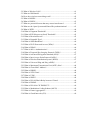
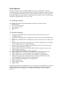
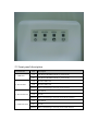
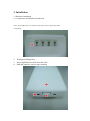
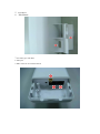
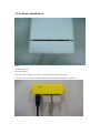
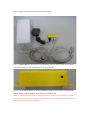
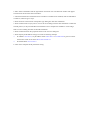
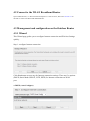
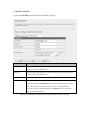
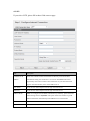
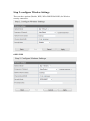
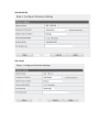
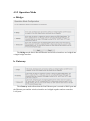
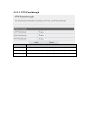
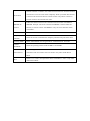
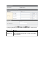
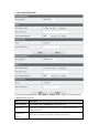
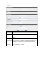
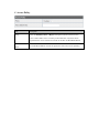
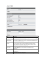
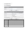
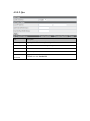
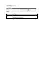
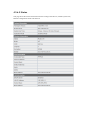
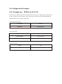
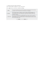
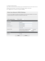
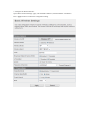
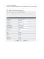
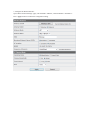
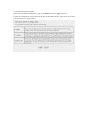
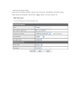
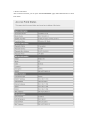
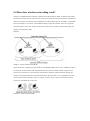
EW-7303APn v2 Quick Installation Guide 11-2011 / v1.0 Table of Contents 1.Terminology ....................................................................................................... 4 2.Introduction ....................................................................................................... 6 2.1 package content ........................................................................................ 6 2.2 product features ........................................................................................ 6 2.3 front panel description ............................................................................. 7 2.4 rear panel description ............................................................................... 8 3. Installation ........................................................................................................ 8 3.1 Hardware Installation ............................................................................... 9 3.1.1 Appearance and Interface Introduction ......................................... 9 3.1.2 Hardware installation steps ......................................................... 11 3.2 Software Installation .............................................................................. 11 4. Software configuration .................................................................................. 12 4.1 Prepare your PC to configure the WLAN Broadband Router ............... 14 4.2 Connect to the WLAN Broadband Router ............................................. 15 4.3 Management and configuration on the Outdoor Router ........................ 17 4.3.1 Wizard ......................................................................................... 17 4.3.2 Operation Mode .......................................................................... 24 4.3.3 Internet Settings .......................................................................... 26 4.3.3.1 LAN ................................................................................. 28 4.3.3.2 VPN Passthrough ............................................................. 30 4.3.4 Wireless Settings ......................................................................... 30 4.3.4.1 Basic ................................................................................. 31 4.3.4.2 Security ............................................................................ 33 4.3.4.3 WPS ................................................................................. 39 4.3.5Administration ............................................................................. 40 4.3.5.1 Management ..................................................................... 40 4.3.5.2 Upload Firmware ............................................................. 42 4.3.5.3 Settings Management ....................................................... 43 4.3.5.4 Status ................................................................................ 45 4.3.5.5 System Log ...................................................................... 45 4.4 Configuration Examples ........................................................................ 47 4.4.1 Example one – PPPoE on the WAN ........................................... 47 4.4.2 Example two – fixed IP on the WAN .......................................... 49 4.4.3 Example three –set WLAN to be WAN as WiFi Client .............. 52 5. FREQUENTLY ASKED QUESTIONS (FAQ)............................................ 56 5.1 What and how to find my PC’s IP and MAC address? .......................... 61 5.2 What is Wireless LAN? ......................................................................... 61 5.3 What are ISM bands? ............................................................................. 61 5.4 How does wireless networking work? ................................................... 62 5.5 What is BSSID? ..................................................................................... 62 5.6 What is ESSID? ..................................................................................... 63 5.7 What are potential factors that may causes interference? ...................... 63 5.8 What are the Open System and Shared Key authentications? ............... 63 5.9 What is WEP? ........................................................................................ 64 5.10 What is Fragment Threshold? .............................................................. 64 5.11 What is RTS (Request to Send) Threshold? ......................................... 65 5.12 What is Beacon Interval? ..................................................................... 65 5.13 What is Preamble Type?....................................................................... 65 5.14 What is SSID Broadcast? ..................................................................... 66 5.15 What is Wi-Fi Protected Access (WPA)? ............................................. 66 5.16 What is WPA2? .................................................................................... 66 5.17 What is 802.1x Authentication? ........................................................... 66 5.18 What is Temporal Key Integrity Protocol (TKIP)? .............................. 67 5.19 What is Advanced Encryption Standard (AES)? ................................. 67 5.20 What is Inter-Access Point Protocol (IAPP)? ...................................... 67 5.21 What is Wireless Distribution System (WDS)? ................................... 67 5.22 What is Universal Plug and Play (uPNP)? ........................................... 67 5.23 What is Maximum Transmission Unit (MTU) Size? ........................... 68 5.24 What is Clone MAC Address? ............................................................. 68 5.25 What is DDNS? .................................................................................... 68 5.26 What is NTP Client? ............................................................................ 68 5.27 What is VPN?....................................................................................... 68 5.28 What is IPSEC? .................................................................................... 68 5.29 What is WLAN Block Relay between Clients? ................................... 69 5.30 What is WMM? .................................................................................... 69 5.31 What is WLAN ACK TIMEOUT? ...................................................... 69 5.32 What is Modulation Coding Scheme (MCS)? ..................................... 69 5.33 What is Frame Aggregation? ............................................................... 69 5.34 What is Guard Intervals (GI)? .............................................................. 69 1.Terminology 3DES Triple Data Encryption Standard AES Advanced Encryption Standard ANSI American National Standards Institute AP Access Point CCK Complementary Code Keying CSMA/CA Carrier Sense Multiple Access/Collision Avoidance CSMA/CD Carrier Sense Multiple Access/Collision Detection DDNS Dynamic Domain Name Server DH Diffie-Hellman Algorithm DHCP Dynamic Host Configuration Protocol DSSS Direct Sequence Spread Spectrum EAP Extensible Authentication Protocol ESP Encapsulating Security Payload FCC Federal Communications Commission FTP File Transfer Protocol IEEE Institute of Electrical and Electronic Engineers IKE Internet Key Exchange IP Internet Protocol ISM Industrial, Scientific and Medical LAN Local Area Network MAC Media Access Control MD5 Message Digest 5 NAT Network Address Translation NT Network Termination NTP Network Time Protocol PPTP Point to Point Tunneling Protocol PSD Power Spectral Density RF Radio Frequency SHA1 Secure Hash Algorithm SNR Signal to Noise Ratio SSID Service Set Identification TCP Transmission Control Protocol TFTP Trivial File Transfer Protocol Temporal Key Integrity Protocol TKIP UPNP Universal Plug and Play VPN Virtual Private Network WDS Wireless Distribution System WEP Wired Equivalent Privacy WLAN Wireless Local Area Network WPA Wi-Fi Protected Access 2.Introduction The EW-7303APn v2 is an affordable IEEE 802.11b/g /n specifications of outdoor AP/Range Extender solution; setting SOHO and enterprise standard for high performance, secure, manageable and reliable WLAN*. This document describes the steps required for the initial IP address assign and other configuration of the outdoor router. The description includes the implementation of the above steps. 2.1 package content The package of the WLAN Broadband Router includes the following items, Outdoor Router DC 12V Power Adapter Documentation CD POE Injector Tie 2.2 product features Compatible with IEEE 802.11n Specifications provides wireless speed up to 150Mbps data rate. Compatible with IEEE 802.11g standard to provide wireless speeds of 54Mbps data rate. Compatible with IEEE 802.11b standard to provide wireless speeds of 11Mbps data rate. Maximizes the performance and ideal for media-centric applications like streaming video, gaming and Voice over IP technology. Support various operation (Bridge/Gateway/Ethernet Converter) modes between wireless and wired Ethernet interfaces. Supports WPS, 64-bit and 128-bit WEP, WPA, WPA2 encryption to protect the wireless data transmission. Support TKIP/AES/TKIPAES of WPA algorithms. Support IEEE 802.3x full duplex flow control on 10/100M Ethernet interface. Support DHCP server to provide clients auto IP addresses assignment. Support DHCP client, static IP, PPPoE, L2TP and PPTP of WAN Interface. Supports firewall security with port filtering, IP filtering, MAC filtering, port forwarding, DMZ hosting and URL filtering functions. Support WEB based management and configuration. Support System Log. Support Dynamic DNS Support NTP *Maximum performance, actual data rates, and coverage will vary depending on network conditions and environmental factors. Product specifications and design are subject to change without notice. Copyright © 2012 Edimax Technology Co. Ltd. All rights reserved. 2.3 front panel description LED Indicator State Description ON The WLAN Broadband Router is powered ON. Off The WLAN Broadband Router is powered Off. ON Wireless Radio ON. Off Wireless Radio Off. 1. PWR LED 2. WLAN LED Flashing 3. WAN LED ACT ON Port linked. Off No link. Flashing 4. LAN LED ACT Data is transmitting or receiving on the wireless. Data is transmitting or receiving on the WAN interface. ON Port linked. Off No link. Flashing Data is transmitting or receiving on the LAN interface. 2.4 rear panel description Interfaces Description For external antenna. You can use the SMA connector to connect with SMA connector 2.4GHz external antenna. The RJ-45 sockets allow LAN connection through Category 5 cables. Secondary(Middle) Support auto-sensing on 10/100M speed and half/ full duplex; comply with IEEE 802.3/ 802.3u respectively. The RJ-45 socket allows WAN connection through a Category 5 cable. Main(Right) Support auto-sensing on 10/100M speed and half/ full duplex; comply with IEEE 802.3/ 802.3u respectively. 3. Installation 3.1 Hardware Installation 3.1.1 Appearance and Interface Introduction Notes: The product shot is for reference only please refer to physical product. 1.LED Panel 2. Waterproof Sliding Door 3. Pass trough Ethernet cable from this cable 4. Push this button to remove upper housing 5. Wall Mount 6. Pole Mount 7. Secondary port with POE 8. Main port 9. SMA connector for external antenna 3.1.2 Hardware installation steps Step2: Pass through Ethernet cable from the hole, insert the cable to Secondary port. Note: RJ-45 8P8C Ethernet cable is required. Step3: Install the upper housing and make sure the housing is well installed. 3.2 Software Installation Step4: Install POE Injector DC: Insert adapter POE: This hole is linked to Secondary port of the Outdoor Router with RJ-45. LAN: This hole is linked to LAN side PC/Hub or Router/ADSL modem device with RJ-45 Step5: Complete the hardware installation as diagram at below Notes: Use Reset button on POE injector. Push continually the reset button of POE injector about 5 ~ 10 seconds to reset the configuration parameters to factory defaults. There is no software driver or utility installation needed, but only the configuration setting. Please refer to chapter 4 for software configuration. Notice: It will take about 50 seconds to complete the boot up sequence after powered on the Outdoor Router; Power LED will be active, and after that the WLAN Activity LED will be flashing to show the WLAN interface is enabled and working now. 4. Software configuration There are web based management and configuration functions allowing you to have the jobs done easily. The Outdoor Router is delivered with the following factory default parameters on the Ethernet LAN interfaces. Default IP Address: 192.168.2.1 Default IP subnet mask: 255.255.255.0 WEB login User Name: admin WEB login Password: 1234 Telnet login User Name: admin Telnet login Password: 1234 4.1 Prepare your PC to configure the WLAN Broadband Router For OS of Microsoft Windows 2000/ XP: 1. Click the Start button and select Settings, then click Control Panel. The Control Panel window will appear. 2. Move mouse and double-click the right button on Network and Dial-up Connections icon. Move mouse and double-click the Local Area Connection icon. The Local Area Connection window will appear. Click Properties button in the Local Area Connection window. 3. Check the installed list of Network Components. If TCP/IP is not installed, click the Add button to install it; otherwise go to step 6. 4. Select Protocol in the Network Component Type dialog box and click Add button. 5. Select TCP/IP in Microsoft of Select Network Protocol dialog box then click OK button to install the TCP/IP protocol, it may need the Microsoft Windows CD to complete the installation. Close and go back to Network dialog box after the TCP/IP installation. 6. Select TCP/IP and click the properties button on the Network dialog box. 7. Select Specify an IP address and type in values as following example. IP Address: 192.168.2.1, any IP address within 192.168.2.2 to 192.168.2.254 is good to connect the Wireless LAN Access Point. Don’t use 192.168.2.1 IP Subnet Mask: 255.255.255.0 8. Click OK to complete the IP parameters setting. For OS of Microsoft Windows Vista / 7: 1. Click the Start button and select Settings, then click Control Panel. The Control Panel window will appear. 2. Move mouse and double-click the right button on Network Connections item. The Network Connections window will appear. Double click Local Area Connection icon, then User Account Control window shown. Right click Continue button to set properties. 3. In Local Area Connection Properties window, Choose Networking tab, move mouse and click Internet Protocol Version 4 (TCP/IPv4), then click Properties button. 4. Move mouse and click General tab, Select Specify an IP address and type in values as following example. IP Address: 192.168.2.1,, any IP address within 192.168.2.1 to 192.168.2.254is good to connect the Wireless LAN Access Point. Don’t use 192.168.2.1 IP Subnet Mask: 255.255.255.0 5. Click OK to complete the IP parameters setting. For OS of Microsoft Windows NT: 1. Click the Start button and select Settings, then click Control Panel. The Control Panel window will appear. 2. Move mouse and double-click the right button on Network icon. The Network window will appear. Click Protocol tab from the Network window. 3. Check the installed list of Network Protocol window. If TCP/IP is not installed, click the Add button to install it; otherwise go to step 6. 4. Select Protocol in the Network Component Type dialog box and click Add button. 5. Select TCP/IP in Microsoft of Select Network Protocol dialog box then click OK button to install the TCP/IP protocol, it may need the Microsoft Windows CD to complete the installation. Close and go back to Network dialog box after the TCP/IP installation. 6. Select TCP/IP and click the properties button on the Network dialog box. 7. Select Specify an IP address and type in values as following example. IP Address: 192.168.2.1, any IP address within 192.168.2.1 to 192.168.2.254 is good to connect the Wireless LAN Access Point. Don’t use 192.168.2.1 IP Subnet Mask: 255.255.255.0 8. Click OK to complete the IP parameters setting. 4.2 Connect to the WLAN Broadband Router Open a WEB browser, i.e. Microsoft Internet Explorer 6.1 SP1 or above, then enter 192.168.2.1 on the URL to connect the WLAN Broadband Router. 4.3 Management and configuration on the Outdoor Router 4.3.1 Wizard This Wizard page guides you to configure Internet connection and Wireless Settings quickly. Step 1: configure Internet connection Click Next button to next step for Internet connection settings. There are five options (DHCP, Static Mode, PPPOE, L2TP, PPTP) for Internet connection on WAN port. a. DHCP (Auto Configure) If you select DHCP option, please click Next button to jump at Step2. b. Static Mode (fixed IP) If you select Static Mode (fixed IP), please fill in these fields on next page. Item Description IP Address Fill in the IP address for WAN interface. Subnet Mask Fill in the subnet mask for WAN interface. Default Gateway Fill in the default gateway for WAN interface out going data packets. Primary DNS Fill in the IP address of Domain Name Server 1. Server Secondary DNS Fill in the IP address of Domain Name Server 2. Server When you finish these settings, then click Next button to jump at Step2. c. PPPOE Connection If you select PPPOE, please fill in these fields on next page. Item Description User Name If you select the PPPoE support on WAN interface, fill in the user name and password to login the PPPoE server. Password If you select the PPPoE support on WAN interface, fill in the user name and password to login the PPPoE server. Verify Password Fill in the password again for verification. Operation Mode Keep Alive: Keep the PPPoE connection all the time. Please also configure the Redial Period field. On Demand: Please configure the Idle Time field. When time is up, the PPPoE connection will disconnect. The connection will re-connect when any outgoing packet arise. Manual: Let user connect the PPPoE connection manually. When you finish these settings, then click Next button to jump at Step2. d. L2TP If you select L2TP, please fill in these fields on next page. Item Description L2TP Server IP Allow user to make a tunnel with remote site directly to secure the data Address transmission among the connection. User can use embedded L2TP client supported by this router to make a VPN connection. If you select the L2TP support on WAN interface, fill in the IP address for it. User Name Fill in the user name and password to login the L2TP server. Password Fill in the user name and password to login the L2TP server. Address Mode Static: To configure the IP address information by manually, please fill in the related setting at below. Dynamic: The option allows the machine to get IP address information automatically from DHCP server on WAN side. IP Address Fill in the IP address for WAN interface. Subnet Mask Fill in the subnet mask for WAN interface. Default Gateway Fill in the default gateway for WAN interface out going data packets. Operation Mode Keep Alive: Keep the L2TP connection all the time. Please also configure the Redial Period field. Manual: Let user connect the L2TP connection manually. When you finish these settings, then click Next button to jump at Step2. e. PPTP If you select PPTP, please fill in these fields on next page. Item Description Item Description PPTP Server IP Allow user to make a tunnel with remote site directly to secure the data Address transmission among the connection. User can use embedded PPTP client supported by this router to make a VPN connection. If you select the PPTP support on WAN interface, fill in the IP address for it. User Name Fill in the user name and password to login the PPTP server. Password Fill in the user name and password to login the PPTP server. Address Mode Static: To configure the IP address information by manually, please fill in the related setting at below. Dynamic: The option allows the machine to get IP address information automatically from DHCP server on WAN side. IP Address Fill in the IP address for WAN interface. Subnet Mask Fill in the subnet mask for WAN interface. Default Gateway Fill in the default gateway for WAN interface out going data packets. Operation Mode Keep Alive: Keep the PPTP connection all the time. Please also configure the Redial Period field. Manual: Let user connect the PPTP connection manually. Step 2: configure Wireless Settings There are three options (Disable, WEP, WPA-PSK/WPA2-PSK) for Wireless security connection. OPEN WEP SHAREDWEP WPA-PSK WPA2-PSK Item Description Network Mode Click to select wireless mode from pull down menu. Frequency (Channel) Select the wireless communication frequency/channel from pull-down menu. Network Name (SSID) It is the wireless network name. The SSID can be 32 bytes long. Channel Bandwidth Select the operating channel width 20 MHz or 20/40 MHz. Security Please select the security mode related wireless data encryption. WEP: When you select WEP, please input 5, 13 (ASCII), 10 or 26 (HEX) characters KEY for WEP Key. WPA-PSK/WPA2-PSK: When WPA/WPA2 Pre-shared key encryption is selected, please fill in the Pre-shared key. The format can be passphrase or Hex (64 characters). When you finish these settings, then click Apply button to save. 4.3.2 Operation Mode a. Bridge: The Bridge mode allows that all Ethernet and wireless interfaces are bridged into a single bridge interface. b. Gateway: The Gateway mode allows that the first Ethernet port is treated as WAN port and the Ethernet port and the wireless interface are bridged together and are treated as LAN ports. c. Wireless ISP The Wireless ISP mode allows that the wireless interface is treated as WAN port, and the Ethernet ports are LAN ports. .4.3.3 Internet Settings 4.3.3.1 LAN Item Description Take NIC MAC address of PC on LAN side as the MAC address of WAN MAC Clone interface. IP Address Fill in the IP address for WAN interface. Subnet Mask Fill in the subnet mask for WAN interface. DHCP Type Disable: Disable DHCP server on LAN side. Server: Enable DHCP server on LAN side. Lease Time Fill in the lease time of DHCP server function. LLTD Select enable or disable the Link Layer Topology Discover function from pull-down menu. LLTD Select enable or disable the Link Layer Topology Discover function from pull-down menu. IGMP Proxy Select enable or disable the IGMP proxy function from pull-down menu. UPNP Select enable or disable the UPnP protocol from pull-down menu. DNS Proxy Select enable or disable the DNS Proxy function from pull-down menu. 4.3.3.3 VPN Passthrough Item Description L2TP Passthrough Select enable or disable the L2TP pass-through function from pull-down menu. IPSec Passthrough Select enable or disable the IPSec pass-through function from pull-down menu. PPTP Passthrough Select enable or disable the PPTP pass-through function from pull-down menu. 4.3.4 Wireless Settings 4.3.4.1 Basic Item Wireless On/Off Description Click Wireless OFF button to turn off wireless RF radio. Click Wireless ON button to turn on wireless RF radio. Select Internal antenna or External antenna for using. The default is using Antenna Switch Internal antenna. Wireless Mode Click to select wireless mode from pull down menu. Wireless Band Click to select wireless band from pull down menu. It is the wireless network name. The SSID can be 32 bytes long. User can use SSID the default SSID or change it. Broadcast Network Name (SSID) Enable or disable the SSID broadcast function. Wireless network is similar to the virtual local area network. All of the Wireless client devices can access each other completely. When you enable this function, AP Isolation it will turn off connection between wireless clients. Only allows connection between wireless client and this AP router. Enable this function will turn off connection between clients with different MBSSID AP MBSSID. Example: The client connected with BSSID 1. When enable this Isolation function, it will not connect with BSSID 2. Only can access between clients with SSID 1. BSSID Show the MAC address of Wireless interface. Frequency Select the wireless communication frequency/channel from pull-down menu. (Channel) Operating Mode Select “Mixed Mode” for 11b/g/n mode or “Green Field” for 11n mode. Channel Select the operating channel width 20 MHz or 20/40 MHz. BandWidth Select “Long” or “Auto”. Guard intervals are used to ensure that distinct Guard Interval transmissions do not interfere with one another. Only effect under Mixed Mode. Select 0~7 or “Auto” from pull down menu. The default is “Auto”. Only effect MCS under Mixed Mode. 4.3.4.2 Security a. Disable f you set Security Mode to “Disable”, the wireless data transmission will not include encryption to prevent from unauthorized access and monitoring. b. OPEN-WEP // SHARED-WEP If you set Security Mode to “OPEN-WEP or SHARED-WEP`”, please fill in the related configurations at below. Item Description Default Key Specify a Key number for effective. WEP Keys (1~4) When you select WEPAUTO, please input 5, 13 (ASCII), 10 or 26 (HEX) characters for WEP Key. c. WPA-PSK/WPA2PSK If you set Security Mode to “WPAPSK or WPA2-PSK”, please fill in the related configurations at below. Item Description WPA Algorithms Select TKIP, AES, or TKIPAES for WPA algorithms. Pass Phrase Please fill in a passphrase like ‘test wpa 123’, or a hexadecimal string like '65E4 E123 456 E1'. Key Renewal Please fill in a number for Group Key Renewal interval time. Interval d. WPA-RADIUS Item Description WPA Algorithms Select TKIP or AES for WPA algorithms. Key Renewal Please fill in a number for Group Key Renewal interval time. Interval IP Address Port Enter the RADIUS Server’s IP Address provided by your ISP. Enter the RADIUS Server’s port number provided by your ISP. (The Default is 1812.) Shared Secret Enter the password that the Wireless Router shares with the RADIUS Server. Session Timeout Session timeout interval is for 802.1x re-authentication setting. Set to zero to disable 802.1x re-authentication service for each session. Session timeout interval unit is second and must be larger than 60. Idle Timeout Enter the idle timeout in the column. e.802.1X Item Description WEP Select Disable or Enable For WEP IP Address Enter the RADIUS Server’s IP Address provided by your ISP. Port Enter the RADIUS Server’s port number provided by your ISP. (The Default is 1812.) Shared Secret Enter the password that the Wireless Router shares with the RADIUS Server. Session Timeout Session timeout interval is for 802.1x re-authentication setting. Set to zero to disable 802.1x re-authentication service for each session. Session timeout interval unit is second and must be larger than 60. Idle Timeout Enter the idle timeout in the column. f. Access Policy Item Description Policy Select the Disabled, Allow or Reject of drop down menu choose wireless access control mode. This is a security control function; only those clients registered in the access control list can link to this WLAN Broadband Router. Add a station Fill in the MAC address of client to register this AP router access capability. MAC 4.3.4.3 WPS Item Description WPS Select Enable or Disable the Wi-Fi Protected Setup function. Then click Apply button to take effect function after change. WPS Summary After enabling the WPS function, if there is connection the WPS Summary will show related information and status. AP PIN Here shows the AP’s PIN code (Personal Identification Number) that the enrollee should enter the registrar’s PIN code to make a connection. Click Generate button to generate a new AP PIN code. Reset OOB Click Reset OOB button to reset WPS AP to the OOB (out-of-box) configuration. WPS mode Select WPS mode. PIN: Personal Identification Number. PBC: Push Button Communication. PIN Input enrollee’s PIN code to AP-registrar. 4.3.5Administration 4.3.5.1 Management Item Description Username Fill in the user name for web management login control. Password Fill in the password for web management login control. Current Time It shows the current time. Time Zone Select the time zone in your country from pull-down menu.. NTP Server Fill in NTP server IP address. NTP Fill in a number to decide the synchronization frequency with NTP server. synchronization Item Description Dynamic DNS Click the drop down menu to pick up the right DDNS provider you registered. Provider Account Fill in the account of DDNS you registered. Password Fill in the password of DDNS you registered. DDNS Fill in the domain name that you registered. 4.3.5.2 Qos Item Description Uplink Speed Input uplink Maximum upload speed Downlink Speed Input downlink Maximum upload speed Local IP Address Fill in the local IP address Uplink Bandwidth Fill limit upload bandwidth Downlink Bandwidth Fill limit downlink bandwidth 4.3.5.3 Upload Firmware Item Description Location Click the Browse button to select the new firmware image file on PC. And click the Apply button to upgrade firmware. 4.3.5.4 Settings Management Item Description Export Button Click Export button to export the current configuration to your PC. Settings file Click Browse button to select the configuration file from your PC, then click location Import button to update the configuration. Load Default Click the Load Default button to reset the configuration parameter to factory Button defaults. This page shows the current status and some basic settings of the device, includes system info, Internet Configurations and Local Network. 4.3.6.5 Status This page shows the current status and some basic settings of the device, includes system info, Internet Configurations and Local Network. 4.3.6.6 System Log This page is used to view system logs Item Description Refresh Click the Refresh button to refresh the log shown on the screen. Clear Click the Clear button to clear the log display screen. 4.4 Configuration Examples 4.4.1 Example one – PPPoE on the WAN Sales division of Company ABC likes to establish a WLAN network to support mobile communication on sales’ Notebook PCs. MIS engineer collects information and plans the WLAN Broadband Router implementation by the following configuration. WAN configuration:PPPoE User Name User123 Password Password123 Note: User Name and password are provided by your ISP LAN configuration: IP Address 192.168.2.1 Subnet Mask 255.255.255.0 DHCP Client Range 192.168.2.100 –192.168.2.200 WLAN configuration: SSID AP Channel Number AutoSelect 1. Configure the Operation Mode Configuration Open “Operation Mode Configuration ” page, select Gateway. Press “Apply” button to confirm the configuration setting. 2. Configure the WAN interface: Open “Wide Area Network (WAN) Settings” page, select PPPoE then enter the User Name “user123” and Password “password123”, the password is encrypted to display on the screen. Press “Apply” button to confirm the configuration setting. . 3. Configure the WLAN interface: Open “Basic Wireless Settings” page, enter the SSID ”Edimax”, Channel Number ”AutoSelect”. Press “Apply” button to confirm the configuration setting. 4. Configure the LAN interface: Open “Local Area Network (LAN) settings” page, enter the IP Address “192.168.2.1”, Subnet Mask “255.255.255.0”. Enable DHCP Server, DHCP client range “192.168.2.100” to “192.168.2.200”, default Gateway “192.168.2.1” . Press “Apply” button to confirm the configuration setting 4.4.2 Example two – fixed IP on the WAN Company ABC likes to establish a WLAN network to support mobile communication on all employees’ Notebook PCs. MIS engineer collects information and plans the WLAN Broadband Router implementation by the following configuration. WAN configuration : Fixed IP IP Address 10.10.10.10 Subnet Mask 255.255.255.0 Default Gateway 10.10.10.1 Primary DNS Address 168.95.1.1 LAN configuration: IP Address 192.168.2.1 Subnet Mask 255.255.255.0 DHCP Client Range 192.168.2.100 – 192.168.2.200 WLAN configuration: SSID Edimax Channel Number AutoSelect 1. Configure the WAN interface: Open “Wide Area Network (WAN) Settings” page, select STATIC(fixed IP) then enter IP Address “10.10.10.10”, subnet mask “255.255.255.0”, Default gateway “10.10.10.1”. Press “Apply” button to confirm the configuration setting. 2. Configure the LAN interface: Open “Local Area Network (LAN) settings” page, enter the IP Address “192.168.2.1”, Subnet Mask “255.255.255.0”. Enable DHCP Server, DHCP client range “192.168.2.100” to “192.168.2.200”, default Gateway “192.168.1.254” . Press “Apply” button to confirm the configuration setting . 3. Configure the WLAN interface: Open “Basic Wireless Settings” page, enter the SSID ” Edimax”, Channel Number ”AutoSelect”. Press “Apply” button to confirm the configuration setting. 4.4.3 Example three –set WLAN to be WAN as WISP User Mr. ABC likes to configure this WLAN Broadband Router to be a WiFi client. In order to communicate with another AP. Mr. ABC collects information and plans the WLAN Broadband Router implementation by the following configuration. WAN configuration: DHCP (Auto config) IP Address n/a Subnet Mask n/a Default Gateway n/a Primary DNS Address n/a LAN configuration: IP Address 192.168.2.1 Subnet Mask 255.255.255.0 DHCP Client Range 192.168.2.100 –192.168.2.200 WLAN configuration: SSID Edimax Channel Number 1 WISP configuration: SSID TestAP Channel Number Channel 6 Wireless Encryption n/a DHCP server 192.168.11.100~192.168.11.200 1. Configure the Operation Mode: Open “Operation Mode Configuration” page, select WISP, then click “Apply” button to confirm the configuration setting and reboot the WLAN Broadband Router. After reboot, the wireless LAN will become to WAN interface. 2. Site Survey: Open “Site Survey” page under Wireless Settings, and select the AP “TestAP”. Press “Next” button to connect with the AP. 3. Wireless encryption setting: If the AP has encryption setting, it will pop out a window for you filling the encryption setting. Please fill up the encryption code and click “Apply” button to connect with the AP. 4. Station Link Status: After connection with AP, you can open “Access Point Status” page under Administration to check Link Status. 5. FREQUENTLY ASKED QUESTIONS (FAQ) 5.1 What and how to find my PC’s IP and MAC address? 5.1 What and how to find my PC’s IP and MAC address? IP address is the identifier for a computer or device on a TCP/IP network. Networks using the TCP/IP protocol route messages based on the IP address of the destination. The format of an IP address is a 32-bit numeric address written as four numbers separated by periods. Each number can be zero to 255. For example, 191.168.1.254 could be an IP address The MAC (Media Access Control) address is your computer's unique hardware number. (On an Ethernet LAN, it's the same as your Ethernet address.) When you're connected to the Internet from your computer (or host as the Internet protocol thinks of it), a correspondence table relates your IP address to your computer's physical (MAC) address on the LAN. To find your PC’s IP and MAC address, Open the Command program in the Microsoft Windows. Type in “ipconfig /all”, then press the Enter button. Your PC’s IP address is the one entitled IP Address and your PC’s MAC address is the one entitled Physical Address. 5.2 What is Wireless LAN? A wireless LAN (WLAN) is a network that allows access to Internet without the need for any wired connections to the user’s machine. 5.3 What are ISM bands? ISM stands for Industrial, Scientific and Medical; radio frequency bands that the Federal Communications Commission (FCC) authorized for wireless LANs. The ISM bands are located at 915 +/-13 MHz, 2450 +/-50 MHz and 5800 +/-75 MHz. 5.4 How does wireless networking work? The 802.11 standard define two modes: infrastructure mode and ad hoc mode. In infrastructure mode, the wireless network consists of at least one access point connected to the wired network infrastructure and a set of wireless end stations. This configuration is called a Basic Service Set (BSS). An Extended Service Set (ESS) is a set of two or more BSSs forming a single sub-network. Since most corporate WLANs require access to the wired LAN for services (file servers, printers, Internet links) they will operate in infrastructure mode. Example xample 1: wireless Infrastructure Mode Ad hoc mode (also called peer-to-peer mode or an Independent Basic Service Set, or IBSS) is simply a set of 802.11 wireless stations that communicate directly with one another without using an access point or any connection to a wired network. This mode is useful for quickly and easily setting up a wireless network anywhere that a wireless infrastructure does not exist or is not required for services, such as a hotel room, convention center, or airport, or where access to the wired network is barred (such as for consultants at a client site). Example 2: wireless Ad Hoc Mode 5.5 What is BSSID? A six-byte address is that distinguish a particular a particular access point from others. Also know as just SSID. Serve as a network ID or name. 5.6 What is ESSID? The Extended Service Set ID (ESSID) is the name of the network you want to access. It is used to identify different wireless networks. 5.7 What are potential factors that may causes interference? Factors of interference: Obstacles: walls, ceilings, furniture… etc. Building Materials: metal door, aluminum studs. Electrical devices: microwaves, monitors and electrical motors. Solutions to overcome the interferences: Minimizing the number of walls and ceilings. Position the WLAN antenna for best reception. Keep WLAN devices away from other electrical devices, eg: microwaves, monitors, electric motors…etc. Add additional WLAN Access Points if necessary. 5.8 What are the Open System and Shared Key authentications? IEEE 802.11 supports two subtypes of network authentication services: open system and shared key. Under open system authentication, any wireless station can request authentication. The station that needs to authenticate with another wireless station sends an authentication management frame that contains the identity of the sending station. The receiving station then returns a frame that indicates whether it recognizes the sending station. Under shared key authentication, each wireless station is assumed to have received a secret shared key over a secure channel that is independent from the 802.11 wireless network communications channel. 5.9 What is WEP? An option of IEEE 802.11 function is that offers frame transmission privacy similar to a wired network. The Wired Equivalent Privacy generates secret shared encryption keys that both source and destination stations can use to alert frame bits to avoid disclosure to eavesdroppers. WEP relies on a secret key that is shared between a mobile station (e.g. a laptop with a wireless Ethernet card) and an access point (i.e. a base station). The secret key is used to encrypt packets before they are transmitted, and an integrity check is used to ensure that packets are not modified in transit. 5.10 What is Fragment Threshold? The proposed protocol uses the frame fragmentation mechanism defined in IEEE 802.11 to achieve parallel transmissions. A large data frame is fragmented into several fragments each of size equal to fragment threshold. By tuning the fragment threshold value, we can get varying fragment sizes. The determination of an efficient fragment threshold is an important issue in this scheme. If the fragment threshold is small, the overlap part of the master and parallel transmissions is large. This means the spatial reuse ratio of parallel transmissions is high. In contrast, with a large fragment threshold, the overlap is small and the spatial reuse ratio is low. However high fragment threshold leads to low fragment overhead. Hence there is a trade-off between spatial re-use and fragment overhead. Fragment threshold is the maximum packet size used for fragmentation. Packets larger than the size programmed in this field will be fragmented. If you find that your corrupted packets or asymmetric packet reception (all send packets, for example). You may want to try lowering your fragmentation threshold. This will cause packets to be broken into smaller fragments. These small fragments, if corrupted, can be resent faster than a larger fragment. Fragmentation increases overhead, so you'll want to keep this value as close to the maximum value as possible. 5.11 What is RTS (Request to Send) Threshold? The RTS threshold is the packet size at which packet transmission is governed by the RTS/CTS transaction. The IEEE 802.11-1997 standard allows for short packets to be transmitted without RTS/ CTS transactions. Each station can have a different RTS threshold. RTS/CTS is used when the data packet size exceeds the defined RTS threshold. With the CSMA/CA transmission mechanism, the transmitting station sends out an RTS packet to the receiving station, and waits for the receiving station to send back a CTS (Clear to Send) packet before sending the actual packet data. This setting is useful for networks with many clients. With many clients, and a high network load, there will be many more collisions. By lowering the RTS threshold, there may be fewer collisions, and performance should improve. Basically, with a faster RTS threshold, the system can recover from problems faster. RTS packets consume valuable bandwidth, however, so setting this value too low will limit performance. 5.12 What is Beacon Interval? In addition to data frames that carry information from higher layers, 802.11 include management and control frames that support data transfer. The beacon frame, which is a type of management frame, provides the "heartbeat" of a wireless LAN, enabling stations to establish and maintain communications in an orderly fashion. Beacon Interval represents the amount of time between beacon transmissions. Before a station enters power save mode, the station needs the beacon interval to know when to wake up to receive the beacon (and learn whether there are buffered frames at the access point). 5.13 What is Preamble Type? There are two preamble types defined in IEEE 802.11 specification. A long preamble basically gives the decoder more time to process the preamble. All 802.11 devices support a long preamble. The short preamble is designed to improve efficiency (for example, for VoIP systems). The difference between the two is in the Synchronization field. The long preamble is 128 bits, and the short is 56 bit 5.14 What is SSID Broadcast? Broadcast of SSID is done in access points by the beacon. This announces your access point (including various bits of information about it) to the wireless world around it. By disabling that feature, the SSID configured in the client must match the SSID of the access point. Some wireless devices don't work properly if SSID isn't broadcast (for example the D-link DWL-120 USB 802.11b adapter). Generally if your client hardware supports operation with SSID disabled, it'snot a bad idea to run that way to enhance network security. However it's no replacement for WEP, MAC filtering or other protections. 5.15 What is Wi-Fi Protected Access (WPA)? Wi-Fi’s original security mechanism, Wired Equivalent Privacy (WEP), has been viewed as insufficient for securing confidential business communications. A longer-term solution, the IEEE 802.11i standard, is under development. However, since the IEEE 802.11i standard is not expected to be published until the end of 2003, several members of the WI-Fi Alliance teamed up with members of the IEEE 802.11i task group to develop a significant near-term enhancement to Wi-Fi security. Together, this team developed Wi-Fi Protected Access. To upgrade a WLAN network to support WPA, Access Points will require a WPA software upgrade. Clients will require a software upgrade for the network interface card, and possibly a software update for the operating system. For enterprise networks, an authentication server, typically one that supports RADIUS and the selected EAP authentication protocol, will be added to the network. 5.16 What is WPA2? It is the second generation of WPA. WPA2 is based on the final IEEE 802.11i amendment to the 802.11 standard. 5.17 What is 802.1x Authentication? 802.1x is a framework for authenticated MAC-level access control, defines Extensible Authentication Protocol (EAP) over LANs (WAPOL). The standard encapsulates and leverages much of EAP, which was defined for dial-up authentication with Point-to-Point Protocol in RFC 2284. Beyond encapsulating EAP packets, the 802.1x standard also defines EAPOL messages that convey the shared key information critical for wireless security. 5.18 What is Temporal Key Integrity Protocol (TKIP)? The Temporal Key Integrity Protocol, pronounced tee-kip, is part of the IEEE 802.11i encryption standard for wireless LANs. TKIP is the next generation of WEP, the Wired Equivalency Protocol, which is used to secure 802.11 wireless LANs. TKIP provides per-packet key mixing, a message integrity check and a re-keying mechanism, thus fixing the flaws of WEP. 5.19 What is Advanced Encryption Standard (AES)? Security issues are a major concern for wireless LANs, AES is the U.S. government’s next-generation cryptography algorithm, which will replace DES and 3DES. 5.20 What is Inter-Access Point Protocol (IAPP)? The IEEE 802.11f Inter-Access Point Protocol (IAPP) supports Access Point Vendor interoperability, enabling roaming of 802.11 Stations within IP subnet. IAPP defines messages and data to be exchanged between Access Points and between the IAPP and high layer management entities to support roaming. The IAPP protocol uses TCP for inter-Access Point communication and UDP for RADIUS request/response exchanges. It also uses Layer 2 frames to update the forwarding tables of Layer 2 devices. 5.21 What is Wireless Distribution System (WDS)? The Wireless Distribution System feature allows WLAN AP to talk directly to other APs via wireless channel, like the wireless bridge or repeater service. 5.22 What is Universal Plug and Play (uPNP)? UPnP is an open networking architecture that consists of services, devices, and control points. The ultimate goal is to allow data communication among all UPnP devices regardless of media, operating system, programming language, and wired/wireless connection. 5.23 What is Maximum Transmission Unit (MTU) Size? Maximum Transmission Unit (MTU) indicates the network stack of any packet is larger than this value will be fragmented before the transmission. During the PPP negotiation, the peer of the PPP connection will indicate its MRU and will be accepted. The actual MTU of the PPP connection will be set to the smaller one of MTU and the peer’s MRU. 5.24 What is Clone MAC Address? Clone MAC address is designed for your special application that request the clients to register to a server machine with one identified MAC address. Since that all the clients will communicate outside world through the WLAN Broadband Router, so have the cloned MAC address set on the WLAN Broadband Router will solve the issue. 5.25 What is DDNS? DDNS is the abbreviation of Dynamic Domain Name Server. It is designed for user owned the DNS server with dynamic WAN IP address. 5.26 What is NTP Client? NTP client is designed for fetching the current timestamp from internet via Network Time protocol. User can specify time zone, NTP server IP address. 5.27 What is VPN? VPN is the abbreviation of Virtual Private Network. It is designed for creating point-to point private link via shared or public network. 5.28 What is IPSEC? IPSEC is the abbreviation of IP Security. It is used to transferring data securely under VPN. 5.29 What is WLAN Block Relay between Clients? An Infrastructure Basic Service Set is a BSS with a component called an Access Point (AP). The access point provides a local relay function for the BSS. All stations in the BSS communicate with the access point and no longer communicate directly. All frames are relayed between stations by the access point. This local relay function effectively doubles the range of the IBSS. 5.30 What is WMM? WMM is based on a subset of the IEEE 802.11e WLAN QoS draft standard. WMM adds prioritized capabilities to Wi-Fi networks and optimizes their performance when multiple concurring applications, each with different latency and throughput requirements, compete for network resources. By using WMM, end-user satisfaction is maintained in a wider variety of environments and traffic conditions. WMM makes it possible for home network users and enterprise network managers to decide which data streams are most important and assign them a higher traffic priority. 5.31 What is WLAN ACK TIMEOUT? ACK frame has to receive ACK timeout frame. If remote does not receive in specified period, it will be retransmitted. 5.32 What is Modulation Coding Scheme (MCS)? MCS is Wireless link data rate for 802.11n. The throughput/range performance of an AP will depend on its implementation of coding schemes. MCS includes variables such as the number of spatial streams modulation, and the data rate on each stream. Radios establishing and maintaining a link must automatically negotiate the optimum MCS based on channel conditions and then continuously adjust the selection of MCS as conditions change due to interference, motion, fading, and other events. 5.33 What is Frame Aggregation? Every 802.11 packet, no matter how small, has a fixed amount of overhead associated with it. Frame Aggregation combines multiple smaller packets together to form one larger packet. The larger packet can be sent without the overhead of the individual packets. This technique helps improve the efficiency of the 802.11n radio allowing more end user data to be sent in a given time. 5.34 What is Guard Intervals (GI)? . A GI is a period of time between symbol transmission that allows reflections (from multipath) from the previous data transmission to settle before transmitting a new symbol. The 802.11n draft specifies two guard intervals: 400ns (short) and 800ns (long). Support of the 400ns GI is optional for transmit and receive. The purpose of a guard interval is to introduce immunity to propagation delays, echoes, and reflections to which digital data is normally very sensitive.