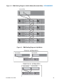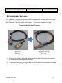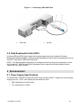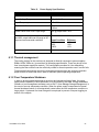
1
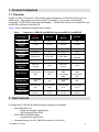
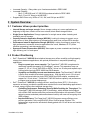
DELL TM POWERVAULT MD1200 & MD1220 TM TECHNICAL GUIDEBOOK Table of Contents 1 Product Comparison ...................................................................................................................... 3 2 1.1 Overview ................................................................................................................................ 3 New Features ................................................................................................................................. 3 3 System Overview ........................................................................................................................... 4 3.1 Customer driven product priorities .......................................................................................... 4 3.2 Product Positioning ................................................................................................................ 4 3.3 PowerVault™ MD1200 and MD1220 Product Features Summary .......................................... 5 4 Product Support ............................................................................................................................. 6 4.1 Host-RAID Adapter Support ................................................................................................... 6 4.2 Host Server Support ............................................................................................................... 6 4.3 Management Software Support .............................................................................................. 6 4.4 Operating System Support ..................................................................................................... 6 4.5 Drive Support ......................................................................................................................... 7 5 Chassis Overview .......................................................................................................................... 8 5.1 Dimensions and Weight.......................................................................................................... 8 5.2 Front View and Features ........................................................................................................ 9 5.3 Back View and Features....................................................................................................... 12 5.4 Hard Drive Indicators ............................................................................................................ 13 5.5 Enclosure Management Module ........................................................................................... 14 5.6 Power Indicator Codes ......................................................................................................... 16 5.7 Solution Configurations ........................................................................................................ 16 5.8 Connecting the Enclosure .................................................................................................... 19 5.9 Field Replaceable Units (FRU) ............................................................................................. 20 6 Environmental .............................................................................................................................. 20 6.1 Power Supply Specifications ................................................................................................ 20 6.1.1 Thermal management................................................................................................... 21 6.1.2 Over-Temperature Shutdown ....................................................................................... 21 6.2 Environmental Specifications................................................................................................ 22 7 Rack Information .......................................................................................................................... 22 7.1 Overview .............................................................................................................................. 22 7.2 Rack Rail Kit ......................................................................................................................... 22 8 Additional Information .................................................................................................................. 23 ** Available in Q3 2010 2 1 Product Comparison 1.1 Overview Evolution of Dell™ PowerVault™ DAS portfolio with the introduction of 6Gb/s SAS (SAS 2.0) in our JBOD arrays. These arrays will connect to Dell™ PowerEdge™ 11G servers using the Dell™ PowerEdge™ RAID (PERC) H800 Host-RAID Adapter. The MD1200 is follow-on to the MD1000, and the MD1220 is follow-on to the MD1120. Table 1 shows a comparison between these versions. Table 1. Comparison of MD1220 and MD1200 to previous MD1120 and MD1000 Feature/Spec NEW MD1220 MD1120 NEW MD1200 MD1000 Rack Units 2U 2U 2U 3U Slot Form Factor 2.5 inch 2.5 inch 3.5 inch 3.5 inch Slots 24 24 12 15 Interface 6Gb (SAS 2.0) 3Gb 6Gb (SAS 2.0) 3Gb Host-RAID Adapter PERC H800 PERC 6/E PERC H800 PERC 6/E PERC5/E EMM Dual Dual Dual Dual Power Supply/Fan Module Dual autosensing Dual Dual autosensing Dual 3.5 inch SAS HDD 3.5 inch SATA HDD HDD Support 2.5 inch SAS HDD 2.5 inch SAS HDD 3.5 inch SAS HDD **2.5 inch SAS HDD SSD Support** **2.5 inch SAS SSD N/A **2.5 inch SAS SSD N/A Storage Management (min rev) Open Manage (6.2) Open Manage (5.4) Open Manage (6.2) Open Manage (4.5.1) RAID Levels 0, 1, 5, 6, 10, 50, 60 0, 1, 5, 6, 10, 50, 60 0, 1, 5, 6, 10, 50, 60 0, 1, 5, 6, 10, 50, 60 2 New Features The PowerVault™ MD1200 and MD1220 offer the following new features: • • • 6Gb/s SAS (SAS 2.0) o Double the throughput performance o Self Encrypting Drives (SED) PERC H800 Host-RAID adapter o Increased IOPs performance Increased Density of the 3.5” (MD1200) enclosure (12 drive 2U) ** Available in Q3 2010 3 • • • Increased Capacity – Daisy chain up to 8 enclosures behind a PERC H800 Increased Flexibility o Mix 2.5” (MD1220) and 3.5” (MD1200) enclosures behind a PERC H800 o Mix 2.5” and 3.5” drives in the MD1200** Supports SAS Drives only; HDDs at 7.2K, 10K, and 15K rpm and SSD** 3 System Overview 3.1 Customer driven product priorities • • • • • Internal Storage no longer enough: Server storage running out, server applications are beginning to bog down, need to move to an external, direct attach storage solution. Single Server Applications: Storage expansion for a single server where clustering and availability are not concerns. Capacity Intensive Application Storage (MD1200): Looking for storage to support very a large volume of data, great solutions for companies that need a low cost per GB for storage. Performance Intensive Application Storage (MD1220): Looking for storage to support very high performance, transaction intensive applications like e-mail, database, OLTP (online transition processing), and data warehousing. Space and Power Conservation (MD1220): Have space or power constraints and looking for high efficiency per U of rack space 3.2 Product Positioning • • Dell™ PowerVault™ MD1200 direct attached storage array offers versatility and high capacity storage for mainstream applications, with optimal performance in sequential (streaming) applications. o Easy to expand your server capacity: The PowerVault™ MD1200 is engineered to seamlessly expand the capacity of PowerEdge™ servers. This expansion array can support 12, 3.5 or 2.5 inch SAS HDDs or SSDs** drives in a 2U array and expands up to 8 arrays behind a single PERC H800 Host-RAID adapter. o Versatility and flexibility to meet most business needs: The PowerVault™ MD1200 is Dell’s most versatile direct attach storage array. With the ability to mix 2.5 inch and 3.5 inch enclosures behind a single PERC H800 Host-RAID adapter, combined with support for 2.5 inch drives**, PowerVault™ MD1200 delivers capacity and performance to support most customer deployments. Dell™ PowerVault™ MD1220, the energy-efficient, small-form-factor (SFF), 2.5-inch drive expansion enclosure, provides the performance required for the most demanding applications in a simple, energy-efficient direct-attached storage array. o Optimizing Performance, Enhancing Security While Doubling the Throughput: The PowerVault™ MD1220 leverages SAS 2.0 technology, which doubles the throughput with a 6Gb/s SAS interface and offers performance optimization with automatic I/O load balancing across redundant paths and enhanced security with new self-encrypting drive (SED) support. o Improved efficiency: The PowerVault™ MD1220 improves energy efficiency over previous generation, with new 80PLUS(R) Silver Certified power supplies. This enhancement augments the efficiencies already gained with 2.5-inch drives and variable speed fans. ** Available in Q3 2010 4 3.3 PowerVault™ MD1200 and MD1220 Product Features Summary Table 2. PowerVault™ MD1200 and MD1220 Features and Descriptions Feature MD1200 MD1220 Rack Height 2U 2U Host interface 6Gb/s SAS (SAS 2.0) 6Gb/s SAS (SAS 2.0) Number of Drive bays 12 – 3.5” 24 – 2.5” Expandability (daisy chain) 8 enclosures per PERC H800 (4 enclosures per port) for a total of 96 drives 8 enclosures per PERC H800 (4 enclosures per port) for a total of 192 drives Redundant Path: up to 4 enclosures per PERC H800 Redundant Path: up to 4 enclosures per PERC H800 Daisy-chain not supported with Split mode Daisy-chain not supported with Split mode Manageability In-Band via SES In-Band via SES Backplane Options Unified (default) or Split mode Unified (default) or Split mode Drive Support SAS HDD and SAS SSD** SAS HDD and SAS SSD** Host-RAID adapter PERC H800 PERC H800 Cluster Support PERC H800: No PERC H800: No Rack or Stand alone Tower Rack Only Rack Only Drive Hot Plug support Yes Yes Hot Plug Fans/blowers Yes – Dual combined fan/power supply module Yes – Dual combined fan/power supply module Hot Plug Power supplies Yes – Dual combined fan/power supply module Yes – Dual combined fan/power supply module SAF-TE, SES Support SES only SES only Enclosure Management configurations Dual Redundant – SBB 2.0 compliant Dual Redundant – SBB 2.0 compliant Power Supply configurations Redundant Redundant Auto-Sensing Auto-Sensing Fans/blowers Redundant Redundant Chassis Dimensions Height 8.68 cm (3.41 inches) Width 44.63 cm (17.57 inches) Depth 60.20 cm (23.70 inches) Weight (max config) 28.39 kg (62.6 lb) Weight (empty) 8.84 kg (19.5 lb) Height 8.68 cm (3.41 inches) Width 44.63 cm (17.57 inches) Depth 54.90 cm (21.61 inches) Weight (max config) 23.31 kg (51.4 lb) Weight (empty) 8.61 kg (19 lb) Weight ** Available in Q3 2010 5 4 Product Support 4.1 Host-RAID Adapter Support The PowerVault™ MD1200 and MD1220 require the PERC H800 for Server connectivity. The PERC H800 is a PCIe 2.0, dual port (2 x4), hardware RAID controller offering 512MB standard battery-backed cache and RAID level support for RAID 0, 1, 5, 6, 10, 50, and 60. The key features of the PERC H800: 6Gb/s SAS (SAS 2.0) Enables daisy-chaining up to 8 enclosures (4 per port) Enables mixing 2.5-inch and 3.5-inch enclosures in the same daisy-chain Enables Redundant Path with Automatic I/O load balancing Supports Self-Encrypting Drive (SED) o Requires specific SED drive part numbers For additional details on PERC H800, visit the PERC web page at www.dell.com/PERC. 4.2 Host Server Support The PERC H800 is supported with Dell™ 11th Generation PowerEdge™ Servers. Refer to Table 3 for PowerEdge™ Servers that support the PERC H800. For the latest PERC H800 support matrix, visit the PERC web page at www.dell.com/PERC. Table 3. PowerEdge™ Servers that support PERC H800 (at initial product launch) Rack Servers Tower Servers PE R210 PE T310 PE R410 PE T410 PE R510 PE T610 PE R610 PE T710 PE R710 4.3 Management Software Support The Dell™ PowerVault™ MD1200 and MD1220 enclosures are managed via the management software provided for the PERC H800. The Dell™ PERC H800 is supported with Dell™ 11th Generation PowerEdge™ Servers and managed via OpenManage™ Storage Management (minimum version 6.2). 4.4 Operating System Support The Dell™ PowerVault™ MD1200 and MD1220 enclosures, via PERC H800, support all major enterprise server operating systems consistent with the Dell™ 11G PowerEdge™ servers and Dell™ OpenManage™ Storage Management (minimum version 6.2) software. This includes Microsoft™ Windows™ Server 2003 and 2008, Red Hat™ Linux 4 and 5, and SUSE™ Linux 10 and 11. For more specific details on supported operating systems, refer to the PERC web page (www.dell.com/PERC) or OpenManage™ 6.2 support matrix. ** Available in Q3 2010 6 4.5 Drive Support Dell™ PowerVault™ MD1200 and MD1220 enclosures support SAS hot-pluggable HDDs (hard-disk drives) and SSDs** (solid-state drives). MD1200 allows for both 3.5-inch and 2.5-inch** form factor drives, and MD1220 allows for 2.5-inch form factor drives. Refer to Table 4 for Drive Support details. Table 4. Form Factor Speed (rpm) Capacity (GB) 7,200 500 GB 10,000 146 GB 300 GB 73 GB 146 GB 2.5” SAS HDDs up to 6Gb/s 15,000 SSDs up to 3Gb/s SSD** 3.5” SAS Drive Support 7,200 HDDs up to 6Gb/s 15,000 150 GB 500 GB 1000 GB (1 TB) 2000 GB (2 TB) 300 GB 450 GB 600 GB SATA interface drives are not supported with the Dell™ PowerVault™ MD1200 and MD1220 enclosures. 6Gb/s SAS interface HDDs and 3Gb/s SAS interface SSDs are configured in the MD1200 and MD1220, from Dell’s factory, and 3Gb/s SAS interface HDDs are supported in the field with the supported MD1200 or MD1220 carrier. The front bezel of the system contains a lock. A locked bezel secures the system hard drives. ** Available in Q3 2010 7 5 Chassis Overview 5.1 Dimensions and Weight The PowerVault™ MD1200 and MD1220 enclosures use a rack mount 2U chassis. Dimensions and Weight Table 5. Model Number PV MD1200 PV MD1220 Detailed Dimensions (mm) Za with bezel Zb Zc Max Sys Weight (kg) Xa Xb Y Za with bezel 481.5 446.3 86.8 38.0 19.0 561.0 602.0 28.39 481.5 446.3 86.8 38.0 19.0 508.0 549.0 23.31 Figure 1. MD1200 and MD1220 Dimensions PowerVault™ MD1200: Weight (maximum configuration) 28.39 kg (62.6 lb) PowerVault™ MD1220: Weight (maximum configuration) 23.31 kg (51.4 lb) ** Available in Q3 2010 8 5.2 Front View and Features Figure 2. ** Available in Q3 2010 MD1200 Front View and Features 9 Figure 3. ** Available in Q3 2010 MD1220 Front View and Features 10 Table 6. Item 1 2 3 4 5 6 MD1200 and MD1220 Front Panel Feature Description FRONT PANEL / BEZEL INDICATOR AND FETAURE DESCRIPTION Indicator, Button, or Icon Description Connector Enclosure status LED The enclosure status LED lights when the enclosure power is on. Lights blue during normal operation and when the host server is identifying the enclosure. Blinks blue when a host server is identifying the enclosure or when the system identification button is pressed. Lights amber when the enclosure is turned on or is reset. Blinks amber when the enclosure is in the fault state. Power LED The power LED lights when at least one power supply is supplying power to the enclosure. Split Mode LED The split mode LED lights when the enclosure is in a split-mode configuration. If the LED is not lit, it indicates that the enclosure is in a unified-mode configuration. System Identification Button The system identification button on the front control panel can be used to locate a particular enclosure within a rack. When the button is pushed, the system status indicators on the control panel and the EMM blinks blue until the button is pushed again. Hard Drives PowerVault™ MD1200—Up to 12 SAS hot-swappable drives. PowerVault™ MD1220—Up to 24 2.5-inchSAS hot-swappable drives. Enclosure Mode Switch When set in the top position, the enclosure is configured in unified mode. When set in the bottom position, the enclosure is configured in split mode. Figure 4. ** Available in Q3 2010 MD1200 and MD1220 Front Bezel Feature and Indicators 11 5.3 Back View and Features Figure 5. Table 7. Item 1 MD1200 / MD1220 Back View and Features MD1200 and MD1220 Back Panel Feature Description BACK PANEL INDICATOR AND FETAURE DESCRIPTION Indicator, Button, or Connector Icon Description Power supply/cooling fan module PS 1 600 W power supply 2 Primary enclosure management module (EMM) EMM 0 3 4 Secondary EMM Power switches (2) EMM 1 Power supply/cooling fan module PS 2 5 ** Available in Q3 2010 For more information, see "Power Indicator codes” section The EMM provides: A data path between the enclosure and the host server. Enclosure management functions for your enclosure The power switch controls the power supply output to the enclosure 600 W power supply 12 5.4 Hard Drive Indicators Figure 6. Hard Drive Indicators (includes HDD and SSD) Table 8. Drive-Status Indicator Pattern (RAID Only) Blinks green two times per second Off Blinks green, amber, and off Blinks amber four times per second Blinks green slowly Steady green Blinks green three seconds, amber three seconds, and off six seconds. ** Available in Q3 2010 Drive Indicator Description Condition Identify drive/preparing for removal Drive ready for insertion or removal NOTE: The drive status indicator remains off until all hard drives are initialized after system power is turned on. Drives are not ready for insertion or removal during this time. The Dell™ PowerEdge™™ RAID controller PERC H800 may take up to a minute to discover and initialize all the hard drives. Drive predicted failure Drive failed Drive rebuilding Drive online Rebuild aborted 13 5.5 Enclosure Management Module Each EMM provides the following data path and enclosure management functions for the enclosure: • Monitoring and controlling enclosure environment elements such as temperature, fan, power supplies, and enclosure LEDs. • Controlling access to hard drives. • Communicating enclosure attributes and states to the host server. Figure 7. Enclosure Management Module Table 9. EMM Indicator Description 2 EMM INDICATOR AND FETAURE DESCRIPTION Indicator, Button, or Icon Description Connector System Status Indicator Blinks blue when the system identification button is pushed. You can identify a particular enclosure in a rack using the system identification indicator. Debug Port For engineering use only. 3 SAS Port (In) 4 In port link status Item 1 5 6 7 SAS Port (Out) Out port link status EMM Status LED ** Available in Q3 2010 IN OUT Provides SAS connections for cabling the host or an up-chain expansion enclosure (unified mode only). Lights green when all the links to the port are connected. Lights amber when one or more links to the port are not connected. The LED remains off if enclosure is not connected. Provides SAS connections for cabling to the next down chain expansion enclosure in a daisy chain (unified mode only). NOTE: The SAS port Out is disabled if the enclosure is running in a split-mode configuration. Lights green when all the links out of the port are connected. Lights amber when one or more links out of the port are not connected. The LED remains off if enclosure is not connected. Lights green when the EMM is functioning properly. Lights amber when the enclosure does not boot or is not properly configured. Blinks green (On 250 ms* Off 250 ms) when a firmware download is in progress. Blinks green (On 1000 ms+ Off 1000 ms) when a peer auto14 Item EMM INDICATOR AND FETAURE DESCRIPTION Indicator, Button, or Icon Description Connector update is in progress. Blinks amber (On 250 ms Off 250 ms [two times]; Off 1000 ms) when the enclosure is unable to communicate with enclosure devices. Blinks amber (On 250 ms *Off 250 ms [four times]; Off 1000 ms) when a firmware update fails. Blinks amber (On 250 ms Off 250 ms [five times]; Off 1000 ms) when the firmware versions are different between two EMMs in an enclosure. *indicates that the LED blinks fast. +indicates that the LED blinks slowly. Enclosure Failover When Two EMMs are Installed If two EMMs are installed, a certain degree of failover is offered. Control and monitoring of the enclosure elements can be transferred from one EMM to another in the event of an EMM failure. A failover occurs whenever communication is lost between an EMM and its peer. In the event of a peer EMM failure, the surviving EMM activates the amber status LED of the failed EMM. The surviving EMM then takes over the responsibility of enclosure management, which includes monitoring and control of the audible alarm, enclosure LEDs, power supplies, and fans. When a failed EMM is replaced, enclosure management functions do not automatically return to the replaced EMM unless an additional failure occurs that triggers another failover event. Note: When the enclosure is configured with dual EMMs in a redundant path configuration, all drives are still accessible, even after an EMM failure, since the EMMs are joined mode via the PERC H800 redundant path. When the enclosure is configured in split mode, only half of the drives are accessible in the event of an EMM failure. EMM Thermal Shutdown If critical internal temperatures are reached, the enclosure shuts down automatically through either a thermal shutdown command issued by the EMM firmware or through a command from Dell™™ OpenManage™ Server Administrator (OMSA). Enclosure Alarms An audible alarm is activated if any of the fault conditions listed below occur. The alarm sounds continuously if: • More than one fan has failed or a power supply/cooling fan module is not installed. • One or more temperature sensors are in critical range. The alarm sounds every 10 seconds if: • One power supply has failed. • One cooling fan has failed. • One or more temperature sensors are in warning range. • One EMM has failed. NOTE: The alarm is disabled by default. To enable the alarm, change the default setting in OMSA. For more information, see the OMSA documentation. ** Available in Q3 2010 15 5.6 Power Indicator Codes Figure 8. Table 10. Item 1 2 3 Power Indicator Codes Power Indicator Description POWER INDICATOR AND FETAURE DESCRIPTION Indicator, Button, or Icon Description Connector DC Power The LED lights green when the DC output voltage is within the limit. If this LED is off, it indicates that the DC output voltages are not within the limit. Power supply/cooling fan The LED lights amber when the DC output voltage is not within fault the limit or a fault with the fan is detected. If this LED is off, it indicates that no fault condition is present. AC Power The LED lights green when the AC input voltage is within the limit. If this LED is off, it indicates either there is no power or the AC input voltage is not within the limit. 5.7 Solution Configurations The PowerVault™ MD1200 and MD1220 enclosures can be cabled in either a unified-mode configuration or in a split-mode configuration. • In a unified-mode configuration the enclosure is connected to one host, for example, a server with a controller card. The enclosure can be one of up to four enclosures daisy-chained to a single port on the controller card in the host server. The enclosure can also be connected in a redundant path mode with two connections to single host server. Redundant path is recommended since it provides cable redundancy and better performance with automatic I/O load balancing. See Figure 9 and Figure 10 for cabling diagrams of unified mode configurations. ** Available in Q3 2010 16 • In a split-mode configuration the enclosure is connected to either two host controllers or two ports on a single host controller. The enclosure can be connected to two different host servers in a split mode configuration. Each server sees the enclosure as an independent device with half of the total enclosure slot capacity. Table 10 lists the drives that are controlled by each enclosure management module (EMM) in a split-mode configuration. See Figure 11 for a cabling diagram of a split-mode configuration. The operating mode is selected using the enclosure mode switch on the front panel of the enclosure. NOTE: The enclosure mode switch must be set to either unified mode or split mode before the enclosure is turned on. Changing the configuration mode after turning on the enclosure has no effect on the enclosure configuration until the enclosure is rebooted. NOTE: Clustering is not supported on PowerVault™ MD1200 and PowerVault™ M1220 enclosures. Figure 9. ** Available in Q3 2010 EMM Cabling Diagram in Unified Mode (Single Path) 17 Figure 10. EMM Cabling Diagram in Unified Mode (Redundant Path) - RECOMMENDED Figure 11. EMM Cabling Diagram in Split Mode ** Available in Q3 2010 18 Table 11. Split Mode Configuration Enclosure EMM0 Dell™ PowerVault™ MD1200 Dell™ PowerVault™ MD1220 Drives 6 to 11 Drives 12 to 23 EMM1 Drives 0 to 5 Drives 0 to 11 5.8 Connecting the Enclosure Dell™ PowerVault™ MD1200 and MD1200 enclosures standardize on the 6Gb/s (SAS 2.0) Mini-SAS cable (SFF 8088). The Mini-SAS cable is unique from the SAS cable used with the previous generation Dell™ PowerVault™ MD1000 and MD1120 enclosures. See transition comparison in Figure 12. Figure 12. Mini-SAS Cable Transition • Connectors on both ends of the SAS cable are universally keyed. Either end of the cable can be connected to the EMM or the RAID controller. • To remove the SAS cable, pull the pull-tab to release the cable from the connector on the EMM and the host system. See Figure 13. ** Available in Q3 2010 19 Figure 13. Connecting a Mini-SAS Cable 5.9 Field Replaceable Units (FRU) Hot swap HDD and SSD, Power Supply Units (power supply/cooling fan modules), Enclosure Management Modules (EMMs), Control Panel and Backplane are the primary field replaceable units on the Dell™ PowerVault™ MD1200 and MD1220. NOTE: For additional detailed instructions on installing and removing enclosure components, refer to the PowerVault™ MD1200 and MD1220 Hardware Owner’s manual and Getting Started Guide at support.dell.com under manuals. 6 Environmental 6.1 Power Supply Specifications The PowerVault™ MD1200 and MD1220 power supply is rated at 600 W. It operates on input voltages ranging from 100 – 240 V, auto-switching to the sensed line level. • • EMC classification is Light Industry FCC classification is Class A ** Available in Q3 2010 20 Table 12. Power Supply Specifications AC Characteristics INPUT PARAMETER Requirement Input Voltage Range 90 – 264 VAC Input Frequency 47 – 63 Hz Peak Inrush Current 55 A for 10ms or less, 25 A for 10150ms Power Factor over full AC input range 0.9 @ output load > 90% Minimum Efficiency measured 20%, 50% and 80% output load over full range of AC input and environmental conditions Must Meet Climate Savers requirements: Peak Output Power 600 Watts Load Condition 20% 50% 100% Efficiency 87% 90% 87% 6.1.1 Thermal management The cooling system for the enclosure is designed to allow all components (power supplies, EMMs, HDDs, SSDs etc.) to meet their full operating specifications. There may be up to four fans in each power supply/fan module. This configuration provides N+1 fan redundancy, meaning that the enclosure can be sufficiently cooled for normal operation even if one fan fails. Firmware shall continuously monitor the temperature sensors within the enclosure and take proper actions to throttle the fans in order to maintain optimal operating temperature. 6.1.2 Over-Temperature Shutdown In order to prevent potential damage to the drives and subsequent loss of data, the power supply has the capability to shut itself down or be shut down by the EMM, through embedded firmware or host management software such as Dell™ Open Manage Storage Management, in the event of an over-temperature condition. When the power supply incorporates its internal thermal shutdown feature, it will automatically restart when the over temperature condition no longer exists. Hysteresis of at least 5 degrees is employed to prevent a frequent toggling on and off of the outputs. ** Available in Q3 2010 21 6.2 Environmental Specifications Table 13. Environmental Specifications Temperature Operating 10° to 35°C (50° to 95°F) with a maximum temperature gradation of 10°C per hour Note: For altitudes above 2950 feet, the maximum operating temperature is de-rated 1°F/550 ft. Storage -40° to 65°C (-40° to 149°F) with a maximum temperature gradation of 20°C per hour Relative Humidity Operating 20% to 80% (non-condensing) with a maximum humidity gradation of 10% per hour Storage 5% to 95% (non-condensing) with a maximum humidity gradation of 10% per hour Maximum Vibration Operating 0.25 G at 3 – 200 Hz for 15 min Storage 0.5 at 3 – 200 Hz for 15 min Maximum Shock Operating Storage One shock pulse in the positive z axis (one pulse on each side of the system) of 31 G for 2.6 ms in the operational orientation Six consecutively executed shock pulses in the positive and negative x, y, and z axes (one pulse on each side of the system) of 71 G for up to 2 ms Altitude Operating -16 to 3048 m (-50 to 10,000 ft) Note: For altitudes above 2950 feet, the maximum operating temperature is de-rated 1°F/550 ft. Storage -16 to 10,600 m (-50 to 35,000 ft) Airborne Contaminant Level Class G2 or lower as defined by ISA-S71.04-1985 7 Rack Information 7.1 Overview The chassis dimensions shall adhere to CEA‐310‐E and Server System Infrastructure (SSI) specifications. Dimensional constraints of the chassis require that the chassis be 2U in height, and comply in width to fit a Dell™ rack. Drives are accessible from the front, while power supply/fan modules, backplane, and EMMs are accessible from the rear. 7.2 Rack Rail Kit Provisions for a rack rail kit are incorporated into the chassis design. The chassis, front panel, and rack kit, when fully assembled together and placed in a rack, must be in compliance with DELL™ Rack Design Guidelines Version 1.1. All critical envelope dimensions referenced in this document assume the inclusion of the rack kit and bezel. Both VersaRail and RapidRail kits are available. ** Available in Q3 2010 22 8 Additional Information • Non-Dell drive lock-out – In order to ensure the highest quality products and best customer experience, the PERC H800 will not allow for non-Dell™ SAS HDDs or SSDs to be initialized or configured in a Dell™ PowerVault™ MD1200 or MD1220. • Backward Compatibility (MD1200) - The PowerVault™ MD1200 does not provide backward compatible support for connecting to previous generation adapters (PERC 5/E or PERC 6/E) or daisy-chaining with previous generation enclosures (MD1000, MD1120, MD3000, MD3000i). MD1200 does support a drive carrier that is common with the Dell™ 11th Generation PowerEdge™ servers. The previous generation PowerVault™ MD1000 carrier is not compatible with the MD1200. • Backward Compatibility (MD1220) - The PowerVault™ MD1220 does not provide backward compatible support for connecting to previous generation adapters (PERC 5/E or PERC 6/E) or daisy-chaining with previous generation enclosures (MD1000, MD1120, MD3000, MD3000i). The MD1220 supports a drive carrier that is common with the Dell™ 11th Generation PowerEdge™ servers and the previous generation PowerVault™ MD1120. • Enclosure Migration and Drive Format – The PowerVault™ MD1200 and MD1220 will not be supported behind Dell’s 3Gb/s PowerVault™ External RAID enclosures, MD3000 and MD3000i. • Audible alarm – The PowerVault™ MD1200 and MD1220 support an audible alarm within the enclosure (must be enabled via OMSS / PERC H800). • EMM blank – An EMM blank must be installed in EMM1 position if a second EMM is not installed. This is required for proper airflow. In order to remove the EMM blank; you will need to remove EMM0 to access a release latch (see Figure 14) for blank. This ensures the customer shuts down the enclosure before making any configuration changes that could but data at risk. Figure 14. Latch ** Available in Q3 2010 23