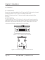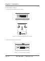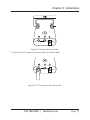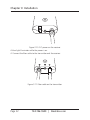
1
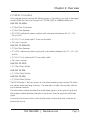
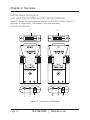
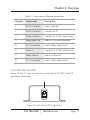
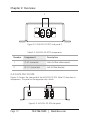
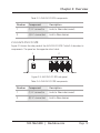
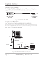
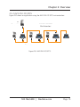
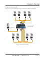
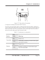
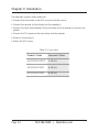
AVX-DVI-FO-MINI AVX-DVI-FO-SP4 AVX-DVI-FO-MINI-RX AVX-DVI-FO-SP8 AVX-DVI-FO-SPCSAVX-DVI-FO-USBPS Mini Extender Kit for DVI-D and Stereo Audio over Fiber Extend DVI-D video and stereo audio up to BLACK BOXfiber or 1.5 kilometers over a strand of single-mode distribute DVI-D and stereo audio to 32 displays. ® Customer Support Information Order toll-free in the U.S.: Call 877-877-BBOX (outside U.S. call 724-746-5500) FREE technical support 24 hours a day, 7 days a week: Call 724-746-5500 or fax 724-746-0746 Mailing address: Black Box Corporation, 1000 Park Drive, Lawrence, PA 15055-1018 Web site: www.blackbox.com • E-mail: [email protected] FCC and IC RFI Statements/NOM Statement FEDERAL COMMUNICATIONS COMMISSION AND INDUSTRY CANADA RADIO FREQUENCY INTERFERENCE STATEMENTS This equipment generates, uses, and can radiate radio-frequency energy, and if not installed and used properly, that is, in strict accordance with the manufacturer’s instructions, may cause interference to radio communication. It has been tested and found to comply with the limits for a Class A computing device in accordance with the specifications in Subpart B of Part 15 of FCC rules, which are designed to provide reasonable protection against such interference when the equipment is operated in a commercial environment. Operation of this equipment in a residential area is likely to cause interference, in which case the user at his own expense will be required to take whatever measures may be necessary to correct the interference. Changes or modifications not expressly approved by the party responsible for compliance could void the user’s authority to operate the equipment. This digital apparatus does not exceed the Class A limits for radio noise emission from digital apparatus set out in the Radio Interference Regulation of Industry Canada. Le présent appareil numérique n’émet pas de bruits radioélectriques dépassant les limites applicables aux appareils numériques de classe A prescrites dans le Règlement sur le brouillage radioélectrique publié par Industrie Canada. Normas Oficiales Mexicanas (NOM)Electrical Safety Statement INSTRUCCIONES DE SEGURIDAD 1. Todas las instrucciones de seguridad y operación deberán ser leídas antes de que el aparato eléctrico sea operado. 2. Las instrucciones de seguridad y operación deberán ser guardadas para referencia futura. 3. Todas las advertencias en el aparato eléctrico y en sus instrucciones de operación deben ser respetadas. Page 2 724-746-5500 | blackbox.com NOM Statement 4. Todas las instrucciones de operación y uso deben ser seguidas. 5. El aparato eléctrico no deberá ser usado cerca del agua—por ejemplo, cerca de la tina de baño, lavabo, sótano mojado o cerca de una alberca, etc. 6. El aparato eléctrico debe ser usado únicamente con carritos o pedestales que sean recomendados por el fabricante. 7. El aparato eléctrico debe ser montado a la pared o al techo sólo como sea recomendado por el fabricante. 8. Servicio—El usuario no debe intentar dar servicio al equipo eléctrico más allá a lo descrito en las instrucciones de operación. Todo otro servicio deberá ser referido a personal de servicio calificado. 9. El aparato eléctrico debe ser situado de tal manera que su posición no interfiera su uso. La colocación del aparato eléctrico sobre una cama, sofá, alfombra o superficie similar puede bloquea la ventilación, no se debe colocar en libreros o gabinetes que impidan el flujo de aire por los orificios de ventilación. 10.El equipo eléctrico deber ser situado fuera del alcance de fuentes de calor como radiadores, registros de calor, estufas u otros aparatos (incluyendo amplificadores) que producen calor. 11. El aparato eléctrico deberá ser connectado a una fuente de poder sólo del tipo descrito en el instructivo de operación, o como se indique en el aparato. 12. Precaución debe ser tomada de tal manera que la tierra fisica y la polarización del equipo no sea eliminada. 13. Los cables de la fuente de poder deben ser guiados de tal manera que no sean pisados ni pellizcados por objetos colocados sobre o contra ellos, poniendo particular atención a los contactos y receptáculos donde salen del aparato. 14.El equipo eléctrico debe ser limpiado únicamente de acuerdo a las recomendaciones del fabricante. 15. En caso de existir, una antena externa deberá ser localizada lejos de las lineas de energia. 724-746-5500 | blackbox.com Page 3 NOM Statement 16.El cable de corriente deberá ser desconectado del cuando el equipo no sea usado por un largo periodo de tiempo. 17. Cuidado debe ser tomado de tal manera que objectos liquidos no sean derramados sobre la cubierta u orificios de ventilación. 18.Servicio por personal calificado deberá ser provisto cuando: A: El cable de poder o el contacto ha sido dañado; u B: Objectos han caído o líquido ha sido derramado dentro del aparato; o C: El aparato ha sido expuesto a la lluvia; o D: El aparato parece no operar normalmente o muestra un cambio en su desempeño; o E: El aparato ha sido tirado o su cubierta ha sido dañada. Page 4 724-746-5500 | blackbox.com Trademarks Used in this Manual Trademarks Used in this Manual Black Box and the Double Diamond logo are registered trademarks of BB Technologies, Inc. Any other trademarks mentioned in this manual are acknowledged to be the property of the trademark owners. 724-746-5500 | blackbox.com Page 5 Contents Contents 1. Specifications............................................................................................... 7 2. Overview . .............................................................................................. 8 2.1 Introduction........................................................................................ 8 2.2 Features.............................................................................................. 8 2.3 What’s Included................................................................................. 9 2.4 Hardware Description.......................................................................10 2.4.1 AVX-DVI-FO-MINI and AVX-DVI-FO-MINI-RX.....................10 2.4.2 AVX-DVI-FO-SPCS.................................................................11 2.4.3 AVX-DVI-FO-SP4...................................................................12 2.4.4 AVX-DVI-FO-SP8...................................................................13 2.4.5 AVX-DVI-FO-USBPS...............................................................14 2.5 System Configuration........................................................................14 2.5.1 AVX-DVI-FO-MINI and AVX-DVI-FO-MINI-RX.....................14 2.5.2 AVX-DVI-FO-SPCS.................................................................15 2.5.3 AVX-DVI-FO-SP4...................................................................16 2.5.4 AVX-DVI-FO-SP8...................................................................17 3. Installation . .............................................................................................18 3.1 Connections......................................................................................18 3.2 EDID Setting......................................................................................18 3.3 Installation Steps.............................................................................. 20 4. Troubleshooting......................................................................................... 25 4.1 Problems/Solutions........................................................................... 25 4.2 Contacting Black Box....................................................................... 26 4.3 Shipping and Packaging................................................................... 26 Page 6 724-746-5500 | blackbox.com Chapter 1: Specifications 1. Specifications Color Depth — 24-bit true color Data Rate — 5 Gbps (2.5 Gbps per single wavelength) Distance — Multimode cable: 1640.4 ft. (500 m); Single-mode cable: 4921.3 ft. (1.5 km) Fiber Type — Single-mode or multimode Optical Budget — 16 dB Receiver Sensitivity — -21 dB Resolutions — Supports up to WUXGA (1920 x 1200) Wavelength — 1310 nm/1550 nm (dual wavelength) Operating Temperature — 32 to 122° F (0 to +50° C) Power Consumption — 2.5 W max. Video Standard — Complies with DVI 1.0 Indicators — (1) two-color LED for Power and Link status Connector — AVX-DVI-FO (kit): Receiver: (1) 24-pin DVI-D, (2) 3.5-mm audio, (1) barrel connector for power; Transmitter: (1) 24-pin DVI-D, (2) 3.5-mm audio, (1) barrel connector for power; Splitters: AVX-DVI-FO-SPCS: (3) LC connectors: (1) for interconnect, (2) for devices; AVX-DVI-FO-SP4: (5) LC connectors: (1) for interconnect, (4) for devices; AVX-DVI-FO-SP8: (9) LC connectors: (1) for interconnect, (8) for devices NOTE: The splitters trasmit both audio and video signals over one single-strand, single-mode fiber cable. Size — 0.6"H x 1.5"W x 2.7"D (1.5 x 3.9 x 6.9 cm) Weight — 0.2 lb. (0.1 kg) 724-746-5500 | blackbox.com Page 7 Chapter 2: Overview 2. Overview 2.1 Introduction The DVI Extender transmits high-quality video signal formats and audio to a remote screen, without compromising the original media quality. The DVI Extender delivers a full HD resolution signal through one fiber optic cable up to 1.5 kilometers. It’s an ideal solution for systems where high-resolution and high-quality video signals need to be displayed over long distances. Connect the extender in a point-to-point configuration to transmit high-resolution video to a remote display. The transmitter module is compatible with all kinds of display devices. It reads and stores the display's EDID information to prevent EDID handshake problems. Installing the extender is easy and more flexible than ever. Connect the extender in a point-to-multipoint configuration to distribute high-resolution video to up to 32 displays. Use the 2-, 4-, and 8-port splitters to achieve flawless video distribution and extenstion. All splitters are passive devices and do not require external power. Typical applications include public informational displays in elevators, trains, subways, airports, shopping malls, museums, or hotels. 2.2 Features • Delivers high-quality multimedia content in real time from a media player to a distant screen while maintaining crystal-clear video. A high-definition video signal from a single player to a display can be extended up to 1.5 km without electrical support for splitters. The DVI Extender increases the range of the display network and enables you to set up your screens at any locations without sacrificing the quality of media. • Supports audio extension. The DVI Extender transmits both audio and video over a single-strand fiber optic cable. • Extends all DVI VESA standards all the way up to a 1920 x 1200 resolution. • Offers programmable EDID. The transmitter reads and stores the display's EDID information and provides a handshaking capability for any type of display with different resolutions. • Consumes very little power. Transmitters and receivers consume 3 W or less for transmitting and receiving Full HD resolution video signals and CD-quality audio. • Split, extend, and distribute DVI video and stereo audio using the passive fiber splitters. Page 8 724-746-5500 | blackbox.com Chapter 2: Overview 2.3 What’s Included Your package should contain the following items. If anything is missing or damaged, contact Black Box Technical Support at 724-746-5500 or [email protected]. AVX-DVI-FO-MINI: • (1) Mini Fiber Transceiver • (1) Mini Fiber Receiver • (2) 5-VDC wallmount power supplies with international adapters for U.S., U.K., AU, and EU • (2) 5-ft. (1.5-m) male-male 3.5-mm audio cables • This user’s manual AVX-DVI-FO-MINI-RX: • (1) Mini Fiber Receiver • (1) 5-VDC wallmount power supply with international adapters for U.S., U.K., AU, and EU • (1) 5-ft. (1.5-m) male-male 3.5-mm audio cable • This user’s manual AVX-DVI-FO-SPCS: • (1) 2-Port Fiber Splitter AVX-DVI-FO-SP4: • (1) 4-Port Fiber Splitter AVX-DVI-FO-SP8: • (1) 8-Port Fiber Splitter The DVI Extender is the best system to use when extending high-quality DVI video and stereo audio over long distances. The extender includes a transmitter module and a receiver module. The transmitter module encodes the audio/video signals into an optical signal and the receiver module decodes the optical signal back into the original audio/video signal. In point-to-point transmission, each display needs a transmitter and a receiver to extend the source. 724-746-5500 | blackbox.com Page 9 Chapter 2: Overview 2.4 Hardware Description 2.4.1 AVX-DVI-FO-MINI and AVX-DVI-FO-MINI-RX Figure 2-1 shows the transmitter and receiver kit (AVX-DVI-O-MINI). Table 2-1 describes its components. The receiver is also sold separately (AVX-DVI-FO-MINI-RX). 1 3 4 2 5 6 7 8 Figure 2-1. Transmitter and Receiver. Page 10 724-746-5500 | blackbox.com Chapter 2: Overview Table 2-1. Transmitter and Receiver components. Number Component Description 1 DVI-D connector Links to monitor 2 DVI-D connector Connects to PC 3 Power connector Connects to 5-VDC power input 4 Stereo audio out Audio in to monitor/speakers 5 (1) LC connector Links to fiber interconnect 6 Power in Connects to 5-VDC power input 7 Stereo audio in Audio out from PC 8 (1) LC connector Links to fiber interconnect 2.4.2 AVX-DVI-FO-SPCS Figures 2-2 and 2-3 show the side panels of the AVX-DVI-FO-SPCS. Table 2-2 describes its components. 1 Figure 2-2. AVX-DVI-FO-SPCS side panel 1. 724-746-5500 | blackbox.com Page 11 Chapter 2: Overview 2 Figure 2-3. AVX-DVI-FO-SPCS side panel 2. Table 2-2. AVX-DVI-FO-SPCS components. Number Component Description 1 (1) LC connector Links to fiber interconnect. 2 (2) LC connectors Link to fiber devices. 2.4.3 AVX-DVI-FO-SP4 Figures 2-4 shows the side panel of the AVX-DVI-FO-SP4. Table 2-3 describes its components. The panel on the opposite side is blank. 1 2 Figure 2-4. AVX-DVI-FO-SP4 side panel. Page 12 724-746-5500 | blackbox.com Chapter 2: Overview Table 2-3. AVX-DVI-FO-SP4 components. Number Component Description 1 (1) LC connector Links to fiber interconnect. 2 (4) LC connectors Link to fiber devices. 2.4.4 AVX-DVI-FO-SP8 Figure 2-5 shows the side panel of the AVX-DVII-FO-SP8. Table 2-4 describes its components. The panel on the opposite side is blank. 1 2 Figure 2-5. AVX-DVI-FO-SP8 side panel. Table 2-4. AVX-DVI-FO-SP8 components. Number Component Description 1 (1) LC connector Links to fiber interconnect 2 (8) LC connectors Link to fiber devices 724-746-5500 | blackbox.com Page 13 Chapter 2: Overview 2.4.5 AVX-DVI-FO-USBPS The AVX-DVI-FO-USBPS is a USB Type A male to a 1.35-mm barrel plug. It can supply 5-VDC to the AVX-DVI-FO-MINI transmitter and/or receiver. USB Type A male connector 1.35-mm barrel connector Figure 2-6. AVX-DVI-FO-USBPS. 2.5 System Configuration 2.5.1 AVX-DVI-FO-MINI and AVX-DVI-FO-MINI-RX The transmitter module encodes the audio/video signal into an optical signal and the receiver module decodes the optical signal back into the original audio/video signal. Figure 2-7 illustrates this application. DVI Media player/PC Transmitter +5 VDC +5 VDC Audio Audio Single-mode fiber cable Monitor Receiver DVI Figure 2-7. AVX-DVI-FO-MINI kit Configuration. Page 14 724-746-5500 | blackbox.com Chapter 2: Overview 2.5.2 AVX-DVI-FO-SPCS Figure 2-8 shows an application using the AVX-DVI-FO-SPCS mini extenders. PC Transmitter AVX-DVI-FO-SPCS Mini Extenders Receivers Figure 2-8. AVX-DVI-FO-SPCS. 724-746-5500 | blackbox.com Page 15 Chapter 2: Overview 2.5.3 AVX-DVI-FO-SP4 Figure 2-9 shows an application using an AVX-DVI-FO-SP4 mini extender. Receiver Receiver PC AVX-DVI-FO-SP4 Mini Extender Transmitter Receiver Receiver Figure 2-9. AVX-DVI-FO-SP4. Page 16 724-746-5500 | blackbox.com Chapter 2: Overview 2.5.4 AVX-DVI-FO-SP8 Figure 2-10 shows an application using an AVX-DVI-FO-SP8 mini extenders. Receivers Receivers PC Transmitter AVX-DVI-FO-SP48 Mini Extender Receivers Receivers Figure 2-10. AVX-DVI-FO-SP8. 724-746-5500 | blackbox.com Page 17 Chapter 3: Installation 3. Installation 3.1 Connections Connect the transmitter module to the DVI port on the PC/video card and connect the receiver module to the DVI port on the digital display device. Use the DVI Extender with an LC fiber optic cable (single-mode optical fiber: 9/125 µm). 3.2 EDID Setting The transmitter has a basic EDID table built in that includes the most commonly used display modes. If you encounter problems selecting the right resolution and would like to copy the EDID table from your monitor, follow these instructions: • Connect the transmitter to the DVI port on the monitor. Figure 3-1. DVI-D connector on the monitor. Figure 3-2. Transmitter plugged into remote monitor. Page 18 724-746-5500 | blackbox.com Chapter 3: Installation • Connect the DC power to the transmitter and power on the monitor. Figure 3-3. DC power on transmitter. • Use a paper clip to press the switch located on the transmitter for a moment. Figure 3-4. Switch on the transmitter. • Check the LED status. If the transmitter has completely read the monitor’s EDID, the blue LED will turn off and on by itself three times. • To use the factory setting, press the switch for 3 seconds. The red LED will blink three times. 724-746-5500 | blackbox.com Page 19 Chapter 3: Installation 3.3 Installation Steps 1. Connect the transmitter to the DVI source. Figure 3-5. DVI source connector. Figure 3-6. Transmitter connected to DVI source. 2. Connect the receiver to the monitor. Figure 3-7. DVI connector on monitor. Page 20 724-746-5500 | blackbox.com Chapter 3: Installation Figure 3-8. Power on the monitor. 3. Connect the DC power to the transmitter and the receiver. Figure 3-9. DC power on the transmitter. 724-746-5500 | blackbox.com Page 21 Chapter 3: Installation Figure 3-10. DC power on the receiver. A blue light illuminates while the power is on. 4. Connect the fiber cable to the transmitter and the receiver. Figure 3-11. Fiber cable on the transmitter. Page 22 724-746-5500 | blackbox.com Chapter 3: Installation Figure 3-12. Fiber cable on the receiver. 5. Power on the display and restart the DVI source. The LED on the transmitter shows a violet light while the transmitter is receiving a normal video signal from the DVI source. Check your DVI source if the LED does not show any activity. The LED on the receiver shows a violet light while the receiver is sensing a normal video signal from the optical cable. Table 3-1. Console port pin assignments. Device Transmitter Receiver LED Color Meaning Blue Power is on. Violet Transmitter is receiving a normal video signal from the DVI source. Blue Power is on. Violet Receiver is receiving a normal video signal from the transmitter. 724-746-5500 | blackbox.com Page 23 Chapter 3: Installation The extender supports audio extension. • Connect the transmitter to the DVI source and audio source. • Connect the receiver to the display and the speaker(s). • Connect the fiber cable between the transmitter and the receiver or connect any splitters. • Connect the DC power to the transmitter and the receiver. • Power on the display(s). • Restart the DVI source. Table 3-2. Loss chart. Page 24 Product Code Amount of Loss AVX-DVI-FO-SPCS 3 dB loss AVX-DVI-FO-SP4 6 dB loss AVX-DVI-FO-SP8 9 dB loss 724-746-5500 | blackbox.com Chapter 4: Troubleshooting 4. Troubleshooting 4.1 Problems/Solutions Problem: No image Solutions: 1. Make sure the PC power is on. 2. Check whether the computer and the monitor are properly connected. 3. Turn the PC power on and off. 4. Make sure the fiber cable between the transmitter and the receiver is properly connected. 5. Check whether the LED on the transmitter shows a violet light. If the LED does not show any activity, the video settings on the PC may be incorrect. 6. Make sure the LED on the receiver shows a violet light. If the LED does not show any activity, the signal from the fiber cable is missing. Check the cable connections. Problem: Screen artifacts appear. Solution: Check the resolution of the DVI source. This device supports up to a 1920 x 1200 WUXGA resolution. Problem: No sound Solutions: 1. Make sure the power is on for the audio source. 2. Check whether the speaker power is on. 3. Make sure the audio cable is correctly connected. 724-746-5500 | blackbox.com Page 25 Chapter 4: Troubleshooting 4.2 Contacting Black Box If you determine that your DVI Extender is malfunctioning, do not attempt to alter or repair the unit. It contains no user-serviceable parts. Contact Black Box Technical Support at 724-746-5500 or [email protected]. Before you do, make a record of the history of the problem. We will be able to provide more efficient and accurate assistance if you have a complete description, including: • the nature and duration of the problem. • when the problem occurs. • the components involved in the problem. • any particular application that, when used, appears to create the problem or make it worse. 4.3 Shipping and Packaging If you need to transport or ship your DVI Extender: • Package it carefully. We recommend that you use the original container. • If you are returning the unit, make sure you include everything you received with it. Before you ship for return or repair, contact Black Box to get a Return Authorization (RA) number. Page 26 724-746-5500 | blackbox.com NOTES 724-746-5500 | blackbox.com Page 27 Chapter Black Box Tech Support: FREE! Live. 24/7. Tech support the way it should be. Great tech support is just 30 seconds away at 724-746-5500 or blackbox.com. About Black Box Black Box provides an extensive range of networking and infrastructure products. You’ll find everything from cabinets and racks and power and surge protection products to media converters and Ethernet switches all supported by free, live 24/7 Tech support available in 30 seconds or less. © Copyright 2012. Black Box Corporation. All rights reserved. AVX-DVI-FO-MINI, version 3 Page 900 724-746-5500 | blackbox.com