1
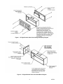
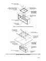
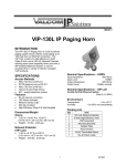
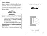
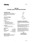
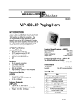
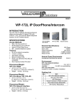
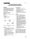
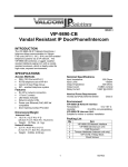
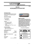
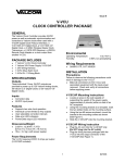
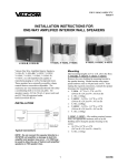
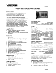
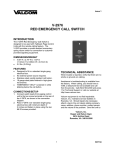
Issue 1
IP PoE Double Sided Digital Clocks
VIP-D425DS, 4 Digit, 2.5” Display, VIP-D440DS, 4 Digit, 4.0” Display
VIP-D625DS, 6 Digit, 2.5” Display, VIP-D640DS, 6 Digit, 4.0” Display
INTRODUCTION
The VIP-D425DS 4 Digit, 2.5 inch, VIP-D440DS
4 Digit, 4.0 inch, VIP-D625DS 6 Digit, 2.5 inch, and
VIP-D640DS 6 Digit, 4.0 inch Clock Displays enable
time indication, synchronization, and correction over
an IP-based LAN/WAN. This allows locating a clock
display anywhere on the network. Clock
synchronization is initiated via connection to a
factory preprogrammed internet time server or can
be programmed to sync with any NTP (Network
Time Protocol) server. The enclosure is made of
steel with a durable powder coated finish. The color
of the enclosure can easily be changed to match
any décor. Power is provided to the digital clocks
via a Power over Ethernet (PoE) switch meeting the
802.3af specification. Only one network connection
is required, supplying power and data to both clock
displays.
SPECIFICATIONS
Features
Easy to read, high visibility Red 2.5” or 4.0”
digits display hours and minutes
Selectable 12 or 24 hour format
802.3af Power over Ethernet (PoE) compatible
High Efficiency
Nominal Power Requirements
802.3af PoE
Class 3
Environment
Temperature:
Humidity:
0 to +40° C
0 to 85% non-precipitating
Packing List
Qty.
1
1
4
1
1
Item
Double Sided Digital Clock
Mounting Bracket
Mounting Bracket Screws w/Nuts
VSP Document
VIP Setup CD
INSTALLATION
FCC Information
DIMENSIONS/WEIGHT
This equipment has been tested and found to
comply with the limits for a Class A digital
device, pursuant to Part 15 of the FCC Rules.
These limits are designed to provide reasonable
protection against harmful interference when
the equipment is operated in a commercial
environment. This equipment generates, uses
and can radiate radio frequency energy and if
not installed and used in accordance with the
instruction manual, may cause harmful
interference to radio communications.
Operation of this equipment in a residential area
may cause harmful interference in which case
the user will be required to correct the
interference at one’s own expense.
VIP-D425DS: 11.50” L x 4.25” W x 5.50” H
(29.21cm L x 10.80cm W x 13.97cm H)
Weight: 5.9 LBS (2.68 kg)
VIP-D440DS: 17.38” L x 4.25” W x 6.85” H
(44.15cm L x 10.80cm W x 17.40cm H)
Weight: 9.1 LBS (4.14 kg)
VIP-D625DS: 16.12” L x 4.25” W x 5.50” H
(40.94cm L x 10.80cm W x 13.97cm H)
Weight: 7.3 LBS (3.32 kg)
VIP-D640DS: 25.25” L x 4.25” W x 6.85” H
(64.14cm L x 10.80cm W x 17.40cm H)
Weight: 12 LBS (5.45 kg)
1
947734
Feed the network cable and seismic cable (if used)
through the cutout in the clock housing before
attaching to the wall or ceiling. Position the clock
housing in the final mounting location and securely
attach to the wall or ceiling with appropriate
fasteners through the four mounting holes in the
bracket.
Precautionary Designations
CAUTION
RISK OF ELECTRIC SHOCK
DO NOT OPEN
CAUTION: To reduce the risk of electric shock,
Do not remove cover.
No user serviceable parts inside.
Refer servicing to qualified service personnel.
This symbol indicates that dangerous
voltage constituting a risk of electric
shock is present within this unit.
This symbol indicates that there are
important operating and maintenance
instructions in the literature accompanying
this unit.
MOUNTING
The Digital Clocks have mounting holes predrilled in
the end and top of the housing, for use with the
included mounting bracket. Additionally, an
optional bridge adapter (model V-9914M-5) is
available for use with tile ceilings.
Reinstall the clock displays into the clock housing,
using Figure 1 as a guide. Insert the RJ-45
connector into the network connection on the clock
display board as shown in Figure 5, then slide the
display onto the housing and secure with the four
screws removed previously. Pull the signal wires
through the housing and reattach to the second
clock display. The connectors are color marked,
and must be reattached to the matching connector
on the clock display. Make sure all wires are inside
the housing, then slide the second clock display
onto the housing. Secure with the four screws
previously removed.
PROGRAMMING
For ease of installation, the digital clock displays
should be removed from the housing before
mounting. Using Figure 1 as a guide, remove the
four screws holding the clock display to the
housing. Carefully pull the clock display away from
the housing, then remove the two wire connectors
from the back of the display. Using the same
process, remove the second clock display.
Programming software is included. Connect the
clock to a PoE switch and scan for the device using
the VIP-102B IP Solutions Setup Tool. Enter the
appropriate network configuration, such as a static
IP address or select DHCP. A default internet time
server IP address is preprogrammed, or a different
NTP Server address may be assigned. The
appropriate time zone should be set.
For end mounting, securely attach the mounting
bracket to the end of the clock housing using the
four screws and nuts provided. Refer to Figure 2
for details.
TECHNICAL ASSISTANCE
For top mounting with the included bracket, refer to
Figure 3. First, remove two screws holding the
blanking plate from the top mounting holes, and
reinstall the blanking plate to cover the end
mounting holes. Securely attach the mounting
bracket to the top of the clock housing using the
four screws and nuts provided.
For top mounting using the optional V-9914M-5
ceiling bridge, use the mounting instructions
provided with the bridge but do not cut the 8.5”
speaker hole in the ceiling tile. Instead, cut a 1”
hole centered within the bridge opening for the
network and seismic cables. Using appropriate
screws and nuts (not provided), attach the clock
housing to the V-9914M-5 bridge with the ceiling tile
between the bridge and the clock housing. Refer to
Figure 4.
2
When trouble is reported, verify power is being
supplied to the unit and there are no broken
connections. If a spare unit is available, substitute a
spare unit for the suspected defective unit.
Assistance in troubleshooting is available from the
factory. Call (540) 563-2000 and press 1 for
Technical Support or via email at
[email protected]
When requesting assistance, you should include all
available information. It is strongly suggested that
you go to the web site and review the
documentation at http://www.valcom.com.
Valcom equipment is not field-repairable. Valcom,
Inc. maintains service facilities in Roanoke, VA.
Should repairs be necessary, attach a tag to the
unit clearly stating your company name, address,
phone number, contact person and the nature of
the problem. Send the unit to:
Valcom, Inc.
Repair & Return Dept.
5614 Hollins Road
Roanoke, Va. 24019-5056
947734
Figure 1. IP Digital Double Sided Clock Wiring and Display Diagram
Figure 2. IP Digital Double Sided Clock Wall Mount Diagram
3
947734
Figure 3. IP Double Sided Clock Ceiling Mount Diagram
Figure 4. IP Digital Double Sided Clock Ceiling Mount with Optional Bridge Diagram (for D440DS,
D625DS, D640DS only) (not for D425DS)
4
947734
RJ-45
Figure 5. Network Connection
VALCOM LIMITED WARRANTY
Valcom, Inc. warrants its products only to the original purchaser, for its own use, to be free from defects in materials and workmanship under
conditions of normal use and service for a period of one year from the date of shipment. This Limited Warranty obligation shall be limited to the
replacement, repair or refund of any such defective device within the warranty period, provided that:
1. inspection by Valcom, Inc. indicates the validity of the claim;
2. the defect is not the result of damage, misuse or negligence after the original shipment;
3. the product has not been altered in any way or repaired by others and that factory sealed units are unopened (a service charge plus parts
and labor will be applied to units defaced or physically damaged);
4. freight charges for the return of products to Valcom are prepaid;
5. all units 'out of warranty' are subject to a service charge. The service charge will cover minor repairs (major repairs will be subject to
additional charges for parts and labor).
This Limited Warranty is in lieu of and excludes all other warranties, expressed or implied and in no event shall Valcom, Inc. be liable
for any anticipated profits, consequential damages, loss of time or other losses incurred by the buyer in connection with the purchase,
operation, maintenance, installation, removal or use of the product. The maximum liability of Valcom under this warranty is limited to
the purchase price of the specific Product covered by the warranty.
Disclaimer. Except for the Limited Warranty provided herein, the product is provided “as-is” without any warranty of any kind whatsoever
including, without limitation, any WARRANTY OF MERCHANTABILITY, FITNESS FOR A PARTICULAR PURPOSE OR NON-INFRINGEMENT.
This warranty specifically excludes damage incurred in shipment. In the event a product is received in damaged condition, the carrier should be
notified immediately. Claims for such damage should be filed with the carrier involved in accordance with the F.O.B. point.
Headquarters:
Valcom, Inc.
5614 Hollins Road Roanoke, VA 24019-5056
Phone: (540) 563-2000 FAX: (540) 362-9800
5
947734