1
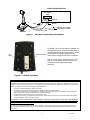
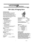
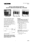
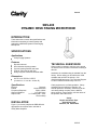
Issue 6
SBS-400
DYNAMIC DESK PAGING MICROPHONE
INTRODUCTION
These instructions contain the specifications and
information necessary to install, operate and
maintain the SBS-400, Dynamic Desk Paging
Microphone.
SPECIFICATIONS
Applications
Clarity Paging Systems
Features
TECHNICAL ASSISTANCE
Dynamic element
Omni-directional pickup pattern
Cycolac housing with die cast base
Push-to-Talk push bar with lock
Heavy duty four-conductor shielded cable
When trouble is reported, verify the unit is turned
on and there are no broken connections leading to
this unit.
Assistance in troubleshooting is available from the
factory. When calling, you should have a VOM
available and call from the job site. Call
(540) 563-2000 and press 1 for Technical Support
or visit or website at www.clarity-com.com
Dimensions
9.375" H x 4.375"W x 5.875"D
(23.8cm H x 11.1cm W x 14.9cm D)
Specifications
Element
Pattern
Frequency Response
Output Impedance
Output Level
Dynamic
Omni-directional
50K to 12KHz
Lo Z 400 Ohms
Lo Z -58db (0db = 1mw/
10 microbars)
Clarity equipment is not field repairable. Clarity
maintains service facilities in Roanoke, VA.
Should repairs be necessary, attach a tag to the
unit clearly stating company name, address,
phone number, contact person, and the nature of
the problem. Send the unit to:
Clarity
Repair and Return Dept.
5614 Hollins Road
Roanoke, VA 24019-5056
INSTALLATION
Figure 1 (on reverse) depicts the SBS-400 with
appropriate connections when used with a
Clarity Mixer-Amplifier.
1
947415
CLARITY MIXER-AMPLIFIER
MIC INPUT
GND
Figure 1 - SBS-400 Connecting Arrangement
SHIELD
RED
BLACK
GREEN (NOT USED)
WHITE (NOT USED)
SBS-400
Figure 1 – SBS-400 Connecting Arrangement
Lift Switch: When the Lift Switch is enabled, the
microphone becomes active when lifted, without
regard to the push-to-talk switch position. When
the Lift Switch is disabled, the push-to-talk
switch must be depressed to active microphone.
High Z / Low Z output: Default position - Low Z.
High Z is utilized when two-wire connection is
necessary or when utilized with legacy
amplifiers.
Figure 2 – Switch Functions
LIMITED WARRANTY
Clarity warrants its products to be free from defects in materials and workmanship under conditions of normal use and service for a
period of one year from the date of shipment. The obligation under this warranty shall be limited to the replacement, repair or refund
of any such defective device within the warranty period, provided that:
1.
2.
3.
4.
5.
Inspection by Clarity indicates the validity of the claim;
The defect is not the result of damage, misuse, or negligence after the original shipment;
The product has not been in any way repaired by others and that factory sealed units are unopened (A service charge plus
parts and labor will be applied to units defaced or physically damaged);
Freight charges for the return of products to Clarity are prepaid,
All units “out of warranty” are subject to a service charge. The service charge will cover minor repairs (Major repairs will be
subject to additional charges for parts and labor).
This warranty is in lieu of and excludes all other warranties, expressed or implied, and in no event shall Clarity be liable for
any anticipated profits, consequential damages, loss of time or other losses incurred by the buyer in connection with the
purchase, operation, or use of the product.
This warranty specifically excludes damage incurred in shipment. In the event a product is received in damaged condition, the
carrier should be notified immediately. Claims for such damage should be filed with the carrier involved in accordance with the
F.O.B. point.
2
947415