1
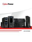
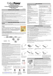
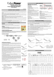
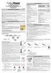
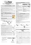
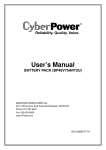
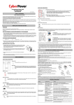
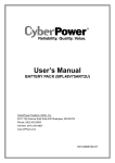
BASIC OPERATION
FRONT / REAR PANEL DESCRIPTION
Smart App Sinewave Series
PR2600LCDRT2U/PR3000LCDRT2U
User’s Manual
K01-0000072-02
IMPORTANT SAFETY WARNINGS
This manual contains important instructions that should be followed during installation and maintenance of the UPS and batteries. Please read
and follow all instructions carefully during installation and operation of the unit. Read this manual thoroughly before attempting to unpack, install,
or operate.
CAUTION! The UPS must be connected to a grounded AC power outlet with fuse or circuit breaker protection. DO NOT plug the UPS into an
outlet that is not grounded. If you need to de-energize this equipment, turn off and unplug the UPS.
CAUTION! DO NOT USE FOR MEDICAL OR LIFE SUPPORT EQUIPMENT! CyberPower Systems does not sell products for life support or
medical applications. DO NOT use in any circumstance that would affect operation or safety of any life support equipment, with any medical
applications, or patient care.
CAUTION! The battery can energize hazardous live parts inside even when the AC input power is disconnected.
CAUTION! For pluggable equipment, the socket-outlet shall be installed near the equipment and shall be easily accessible.
CAUTION! To prevent the risk of fire or electric shock, install in a temperature and humidity controlled indoor area, free of conductive
contaminants. (Please see specifications for acceptable temperature and humidity range).
CAUTION! To reduce the risk of electric shock, do not remove the cover, except to service the battery. There are no serviceable parts inside,
except for the battery.
CAUTION! To avoid electrical shock, turn off the unit and unplug it from the AC power source before servicing the battery or installing a
computer component.
CAUTION! DO NOT USE WITH OR NEAR AQUARIUMS! To reduce the risk of fire, do not use with or near aquariums. Condensation from
the aquarium can come in contact with metal electrical contacts and cause the machine to short out.
CAUTION! For model PR2600LCDRT2U and PR3000LCDRT2U –For use in a computer room as defined in the Standard for the Protection of
Electronic Computer/Data Processing Equipment, ANSI/NFPA 75.
INSTALLING YOUR UPS SYSTEM
UNPACKING
Inspect the UPS upon receipt. The box should contain the following.
(1) UPS Unit; (1) User's Manual for UPS; (2) Rack mount Brackets; (2) Stands; (2) Skids; (1) Telephone Cable (black); (1) Emergency Power Off
Cable (gray); (1) PowerPanel® Business Edition Software CD; (2) Serial Interface Cable (DB-9); (1) USB A+B type cable; (1) Warranty
Registration Card.
1. Power Switch
Master On/Off switch for equipment connected to the UPS.
2. Power on Indicator
Indicate that the AC utility input power’s condition is normal and that the
UPS outlets are providing power, free of surges and spikes.
3. Multifunction LCD Readout
An LCD that shows various UPS information using icons and messages.
4. LCD Readout Toggle Button
Used to select among a variety of information the LCD can display.
5. Battery Backup & Surge Protected Outlets
This unit provides a total of nine outlets with battery backup and surge
protection. They ensure that connected equipment will keep an
uninterrupted operation over a period of time, during a power failure.
Critical /Non-critical
It is possible to program the unit in a way so that the outle block marked as
“non-Critical”, (5 ports), will stop the provision of power to connected
equipment after a certain period of time, thus making more runtime
available for the equipment connected on the outlets marked as “Critical”,
(4 ports). In other words, the user can establish runtime priority for certain
connected equipment, maximizing its “availability” during a prolonged
power outage.
6. Input Power Cord
Heavy-duty, extra long power cord.
7. Output Circuit Breaker
The circuit breaker serves to provide output overload and fault protection.
8. Input Circuit Breaker
The circuit breaker serves to provide input overload and fault
protection.
9. USB port to PC
This is a connectivity port allowing communication and control
among the UPS and the connected computer. You should install
on your computer the PowerPanel® Business Edition software
appropriate to the operating system you are using.
10. Surge Protected Communication Ports - RJ11/RJ45
These ports are being used to protect from various
surge-conditions the standard RJ-45/RJ-11 based, (ADSL, LAN,
Phone/Modem-Lines), cabling systems.
11. Site Wire Fault Indicator
This LED will illuminate to warn the user that a wiring problem exists
within the AC receptacle, such as a bad ground, missing ground or
reversed wiring. If illuminated, disconnect all equipment and contact
an electrician to ensure outlet is properly wired.
12. Serial Port I (Primary)
Serial port I allow for bi-directional communication among the UPS
and the computer. The UPS can control the computer’s shutdown in
case of an emergency, and at the same time, the computer can
monitor the UPS and alter its various programmable parameters.
13. Serial Port II (Secondary)
Serial Port II allows the UPS to initiate the connected computer’s
graceful auto-shutdown in case of an emergency.
14. SNMP/HTTP Network slot
Remove the cover panel to install optional SNMP, allowing your UPS
be controlled and monitored via a network connection.
15. EPO (Emergency Power Off) Port:
Allow for an emergency UPS Power-Off from a remote location.
16. Ground Stud
Use the Ground Stud to ground the UPS.
17. Extended Runtime (XL) Battery Pack Connector
Provide a connection for additional CyberPower XL Battery Packs.
BATTERY REPLACEMENT
OVERVIEW
The PR2600LCDRT2U/PR3000LCDRT2U provides battery backup, automatic voltage regulation (AVR), and
optimal performance of computers and other network equipment by ensuring consistent sinewave power. The
PR2600LCDRT2U/PR3000LCDRT2U features 1874 Joules of surge protection, and provides battery backup
during power outages. The PR2600LCDRT2U/PR3000LCDRT2U ensures consistent power to your
computer system and its included software will automatically save your open files and shutdown your
computer system during a utility power loss.
AUTOMATIC VOLTAGE REGULATOR(AVR)
The PR2600LCDRT2U/PR3000LCDRT2U stabilizes inconsistent utility power. The incoming utility power may be damaging to important data
and hardware, but with Automatic Voltage Regulation, the computer will not experience damaging voltage levels. An Automatic Voltage Regulator
automatically increases low or decreases high voltage to a consistent, computer safe 110v/120v. The unit powerful sealed lead-acid batteries will
provide power only if the incoming voltage drops below 80v or increases above 150v.
SYSTEM BLOCK DIAGRAM
Contact your dealer, or email [email protected]. Refer to replacement battery pack number RBP852 for the PR2600LCDRT2U/
PR3000LCDRT2U.
For model PR2600LCDRT2U/ PR3000LCDRT2U can support model BP48V75ART2U for external battery pack.
Read and follow the IMPORTANT SAFETY INSTRUCTIONS before servicing the battery. Service the battery under the supervision of personnel
knowledgeable of batteries and their precautions. Servicing the battery should only be performed by trained personnel.
Replacement of batteries located in an OPERATOR ACCESS AREA.
CAUTION! When replacing batteries, replace with the same number of the following battery: HR9-12(BB) for PR2600LCDRT2U/
PR3000LCDRT2U.
CAUTION! Risk of Energy Hazard, 12 V, maximum 9 Ampere-hour battery (HR9-12). Before replacing batteries, remove conductive jewelry
such as chains, wrist watches, and rings. High energy through conductive materials could cause severe burns.
CAUTION! Risk of battery explosion, if battery is replaced by an incorrect type. Dispose of used battery according to the instructions.
CAUTION! To reduce the risk of fire, connect only to a circuit provided with 30 amperes maximum branch circuit overcurrent protection in
accordance with the National Electric Code, ANSI/NFPA 70.
CAUTION! A MAXIMUM of five additional battery packs can be added to models PR2600LCDRT2U/PR3000LCDRT2U.
CAUTION! Use only the specified CyberPower replacement battery, or battery pack. See your dealer for details.
CAUTION! The battery may present a risk of electrical shock. Do not dispose of batteries in a fire, as they may explode. Follow all local
ordinances regarding proper disposal of batteries.
CAUTION! Do not open, or mutilate the batteries. Released electrolytes may be toxic, and can be harmful to skin and eyes.
CAUTION! A battery may present a high risk of short circuit current and electrical shock.
Take the following precautions before replacing the battery:
1. Remove all watches, rings or other metal objects.
2. Only use tools with insulated handles.
3. Do not lay tools or metal parts on top of battery or any terminals.
4. Wear rubber gloves and boots.
5. Determine if the battery is inadvertently grounded. If inadvertently grounded, remove source of ground. CONTACT WITH A GROUNDED
BATTERY CAN RESULT IN ELECTRICAL SHOCK! The likelihood of such shock will be reduced if such grounds are removed during installation
and maintenance (applicable to a UPS and a remote battery supply not having a grounded circuit)
HARDWARE INSTALLATION GUIDE
1. Battery charge loss may occur during shipping and storage. For the first time the UPS is used, it’s strongly recommended to charge batteries
for at least eight hours is recommended to ensure that the batteries’ maximum charge capacity. To recharge the batteries, simply make the UPS
plugs into an AC outlet.
2. When you use the included software, connect either the serial or the USB cable between the computer and the corresponding port on the UPS.
Note: If the USB port is used, the serial port will be disabled. They cannot be used simultaneously. The computer with the PowerPanel® Business
Edition S/W connects to the USB port or the Serial port on the UPS. It can control the operating schedule, battery test, outlet, etc. and get
information on the UPS status. However, other computers with PowerPanel® Business Edition S/W can only get UPS status information via a
LAN connection.
3. With the UPS off and unplugged, connect your computer, monitor, and any externally powered data storage device (Hard drive, Tape drive, etc.)
into the outlets. DO NOT plug a laser printer, copier, space heater, vacuum, paper shredder or other large electrical device into the UPS. The
power demands of these devices will overload and possibly damage the unit.
4. To protect a fax, telephone, modem line or network cable, connect the telephone or network cable from the wall jack outlet to the jack marked
“IN” of the UPS. Then, connect a telephone cable or network cable from the jack marked “OUT” on the UPS to the modem, computer, telephone,
fax machine, or network device.
5. Press the power switch to turn the UPS on. The Power-On indicator light will illuminate. If an overload is detected, an audible alarm will sound
and the UPS will emit one long beep. In order to reset it, turn the unit off and unplug some equipment from outlets. Make sure your equipment
carry a load current within the unit’s safe range, (refer to the technical specifications), and then turn the unit on.
6. Your UPS is equipped with an auto-charge feature. When the UPS is plugged into an AC outlet, the battery will be automatically charging, even
when the unit is switched off!
7. To always maintain an optimal battery charge, leave the UPS plugged into an AC outlet at all times.
8. Before storing the UPS for an extended period of time, turn the unit OFF. Then cover it and store it with the batteries fully charged. Recharge
the batteries every three months or so, to ensure good battery capacity and long battery life; further, this might also prevent damage to the unit
from an unlikely battery leakage.
9. The unit provides one Primary Serial Port (I), Secondary Ser city and long battery life; further, this might also prevent damage to the unit from
an unlikely battery leakage.ial Port (II), and one USB port, (paired with the Primary Serial Port), to allow connection and communication between
the unit and any attached computers. The Primary Serial Port (I) as well as its paired USB port allow for bi-directional communication among the
UPS and the primary connected computer running the PowerPanel® Business Edition S/W provided. The UPS can control the computer’s
shutdown in case of an emergency, and at the same time, the computer can monitor the UPS and alter its various programmable parameters. On
the other hand, secondary Serial Port II, only allows the UPS to initiate the connected computer’s graceful auto-shutdown in case of an
emergency.
10. EPO (Emergency Power Off) Port:
Use the provided gray cable to connect to a special EPO contact switch. Follow the appropriate circuit diagram
below to wire the cable to your EPO configuration. The EPO remote switch is a switch installed in an outside
area, connected to the unit via an ordinary RJ-11 phone line. In case of an emergency, it can be used to
immediately cut-off power from the UPS unit.
Dry connect is controlled by the PowerPanel®
Software, please go to www.cyberpowersystems.com
for free download.
*NOTE: Both USB and Serial cannot be used
simultaneously.
The primary computer
with PowerPanel®
Business Edition
software connected to
the UPS with either a
serial cable or a USB
cable.
The equipment can
read information
via dry contact.
BATTERY REPLACMENT PROCEDURE:
1
1.Remove the six retaining screws,
and remove the front panel.
4
4. Disconnect the black and red cable
2
3
3. Remove the cable protection cover.
2. Remove the one retaining screws of
the cable protection cover then remove
the cover.
6
5
5. Remove the three retaining screws.
6. Pull out the old battery pack and replace.
Reassemble the retaining screws, covers, black and
red cable, and front panel in the reverse sequence
of the above steps. Recharge the unit for 4-8 hours
to ensure maximum UPS battery runtime.
LCD STATUS DEFINITION
INPUT voltage meter: This meter measures the AC voltage from the wall outlet. The INPUT voltage readout is used to identify the input voltage
information. This can be used as a diagnostic tool to identify poor-quality input power. Units are listed in V (Volts). When the UPS connect to
any equipment, the AVR can provide a stable 110/120V power output. In the event of a complete loss of power, severe brownout, or over
voltage, the UPS relies on its internal battery to back up to supply a consistent 110/120V output.
OUTPUT voltage meter: The Output Voltage screen measures, in real time, the AC voltage that the UPS is providing to your connected
equipment via the UPS outlets. Units are listed in V (Volts).
ESTIMATE RUN TIME: The Estimated Runtime Screen displays how many minutes of runtime can be expected of the UPS if it were to
experience a power outage. When runtime becomes shorted, the battery capacity will decrease; (battery capacity bar indicator will be falling.)
Note: The number displayed may be less than actual runtimes for low loads.
NORMAL icon: This icon illuminates when the UPS is working under normal conditions.
BATTERY icon: When there is a severe brownout or blackout, this icon will appear followed by an alarm, (two short beeps), indicating that the
UPS is now working using its internal batteries. Once the batteries are run out of power, (over a period of time), a constant alarm will sound. If this
happens and main power has not been restored, it is recommended that you save your files and turn off your equipment manually as soon as
possible.
Automatic Voltage Regulation (AVR) icon: This icon will appear when the unit is automatically regulating low or high AC input line voltage
conditions, without resulting to the use of battery power.
SILENT MODE icon: This icon appearing indicates that the buzzer will not be beeping while in battery operating mode. During Silent mode, the
unit’s alarm does not sound until the Battery Capacity falls to < 20%.
OVER LOAD icon: This icon will appear followed by an alarm, indicating that an overload condition has been reached. To recover from the
overload condition, start unplugging your equipment from the UPS outlets until the icon disappears and the alarm stops.
FAULT icon: When activated indicates a system fault error. Please refer to the troubleshooting table for possible causes and solutions.
BATT. CAPACITY meter: BATT. CAPACITY is shown as a bar chart; each segment indicates approximately a 20% of battery capacity.
LOAD CAPACITY: Load CAPACITY is shown as a bar chart; each segment indicates approximately a 20% of load capacity.
LCD STATUS AND SETUP FUCTIONS
CYBERPOWER GREENPOWER UPS™ TECHNOLOGY
1. General Mode
a. Press the “Display” button to check the status of the UPS.
b. Press and hold the “Display-Toggle” button for 4 seconds,
If the machine is in the Battery Mode with active alarm, it will become silent.
If the machine is in the Line Mode, a self- diagnostic test will take place.
c. If the “Display-Toggle” button remains untouched for over 30 seconds, the LCD
backlight will turn off automatically.
2. Set-up Mode
Step 1: Hold the “Display-Toggle” button for 10 seconds to enter the UPS Set-Up
Mode.
Step 2: By pressing the Display toggle, users can switch between setup functions.
Some User Configurable functions are as follows:
Items
Unit
1
Input Voltage
V
2
Output Voltage
V
3
Output Frequency
Hz
4
Load
Kw
5
Estimate Run Time
Min
6
Load Capacity
%
7
Battery Capacity
%
8
Centigrade
℃
9
Fahrenheit
℉
a. Delay Time: The time delay between switching from Battery Mode to Line Mode. There are 9 different settings. The default
setting is 0 minutes.
b. Battery Pack Numbers: This function provides the estimated UPS runtime using various numbers of battery packs. The default
setting is 0.
c. Static Frequency Tolerance: There are 6 settings (1,2,4,6,8,10 %), and the default setting is +/-6%. Functional description: The
setting may be adjusted to the quality of the electricity in use.
d. Slew rate: Also known as Dynamic Frequency Tolerance. There are 5 different settings (0.25,0.5,1,2,4 Hz/Sec). The fault value
is 4Hz/sec. Functional Description: “Slew Rate” indicates the tolerance of a device in accepting frequency variance. Lower
“Slew Rate” results in less tolerance but better protection for the connected load and vice versa.
e. Low Battery Shutdown Voltage: This function will adjust the UPS shutdown point according to the battery’s remaining capacity.
Note! If the UPS is left idle for over 30 seconds during setup, it will turn off
the backlight and return to general mode automatically.
Note! If the user does not want to save the new settings and return to the
general mode, there are two methods:
1. Wait for the backlight to turn off, or,
2. By pressing and holding the “Display-toggle” key for 10 second.
Items
Unit
Delay Time
Min
Battery Pack Numbers
A
Static Frequency Tolerance
%
Slew Rate
Hz
Battery Shutdown Voltage
V
TROUBLE SHOOTING
Outlet do not provide power to
equipment
The UPS does not perform
expected runtime.
The UPS will not turn on.
PowerPanel® Personal
Edition is inactive
Solution
Circuit breaker has tripped
due to an overload.
Turn the UPS off and unplug at least one piece of equipment. Wait
10 seconds, reset the circuit breaker by depressing the button, and
then turn the UPS on.
Batteries are discharged
Recharge the unit for at least 4 hours
Unit has been damaged by
a surge or spike.
Uncritical outlets have
turned off automatically
due to an overload
Contact CyberPower Systems about replacement batteries at
[email protected]
Battery not fully charged.
Recharge the battery by leaving the UPS plugged in.
Battery is degraded
Contact CyberPower Systems about replacement batteries at
[email protected]
The on/off switch is
designed to prevent
damage by rapidly turning
it off and on.
Turn the UPS off. Wait 10 seconds and then turn the
UPS on.
The unit is not connected
to an AC outlet.
The unit must be connected to a 110/120v outlet.
The battery is worn out.
Contact CyberPower Systems about replacement batteries at
[email protected]
Mechanical problem.
Contact CyberPower Systems at [email protected]
The serial cable or USB
cable is not connected.
Connect the cable to the UPS unit. You must use the cable that
came with the unit.
The cable is connected to
the wrong port.
Try another port of your computer
The unit is not providing
battery power.
Shutdown your computer and turn the UPS off. Wait 10 seconds
and turn the UPS back on. This should reset
the unit.
The serial cable is not the
cable that was provided
with the unit.
You must use the cable included with the unit for the
software
Push the toggle button to make the uncritical outlets turn on.
TECHNICAL SPECIFICATIONS
Capacity(Watts)
Input
Input Plug Type
Input Voltage Range
Input Frequency Range
Output
On Battery Output Voltage
On Battery Output Frequency
Transfer Time(Typical)
Overload Protection
Surge Protection and Filtering
Lightning/Surge Protection
Internet Ready(DSL/Phone/
FAX/Modem Protection)
Physical
Output Receptacles
Dimensions(cm)
Weight (Kg)
Battery
Sealed Maintenance Free Lead
Acid Battery
Extension Runtime
Hot Swappable External Battery
Warning Diagnostics
Indicators
Audible Alarms
Environmental
Operating Temperature
Operating Relative Humidity
Communication
PowerPanel® Business Edition
Management
Self-Test
Auto-Charger/ Auto-Restart
COM Interface
Built-in USB Interface
SNMP/ HTTP Network Slot
Read the following terms and conditions carefully before using the CyberPower PR3000LCDRTXL2U (the "Product"). By using the Product you
consent to be bound by and become a party to the terms and conditions of this Limited Warranty and Connected Equipment Guarantee (together
referred to as this "Warranty"). If you do not agree to the terms and conditions of this Warranty, you should return the Product for a full refund prior
to using it.
Who is Providing this Warranty?
CyberPower Systems (USA), Inc. ("CyberPower") provides this Limited Warranty.
What Does This Warranty Cover?
This warranty covers defects in materials and workmanship in the Product under normal use and conditions. It also covers equipment that was
connected to the Product and damaged because of the failure of the Product.
PR2600LCDRT2U
2600
PR3000LCDRT2U
3000
2100
2250
NEMA L5-30P
80Vac-150Vac
50/60Hz+/-3Hz(auto sensing)
Pure Sine Wave at 120Vac+/-5%
50/60+/- 0.1Hz
4 ms
On Utility: Circuit Breaker, On Battery: Internal Current Limiting
Yes
RJ11/RJ45(One In/One Out)
(8)NEMA 5-20R (1)L5-30R
2U Rack, 43.3 x 8.8 x 48
36.2
37
12V / 9.0AHx4
Extension Runtime for 5 Battery Pack
Yes
Power On, Wiring Fault, LCD Display (Using Battery, AVR, Load Level, Battery Level)
On Battery, Low Battery, Overload
32oF to 104oF ( 0oC to 40 oC )
0 to 95% Non-Condensing
Windows 98/ME/NT/2000/XP, Vista, Windows 7
Manual Self-Test
Yes
True RS232 x1+ Contact Closure x1
Yes
Yes
Who Is Covered?
This warranty only covers the original purchaser. Coverage ends if you sell or otherwise transfer the Product.
How Do You Get Service?
1. Call us at (877) 297-6937 or write to us at Cyber Power Systems (USA), Inc., 4241 12th Ave. E., STE 400, Shakopee, MN 55379 or send us an
e-mail message at [email protected] for instructions.
2. When you contact CyberPower, identify the Product, the Purchase Date, and the item(s) of Connected Equipment. Have information on all
applicable insurance or other resources of recovery/payment that are available to the Initial Customer and Request a Claim Number.
3. You must provide a dated Proof-of-Purchase receipt (or other proof of the original purchase) and provide a description of the defect.
4. Pack and ship the product with a dated Proof- of-Purchase receipt to CyberPower and, if requested, the item(s) of Connected Equipment, a
repair cost estimate for the damage to the Connected Equipment, and all claim forms that CyberPower provides to you. Show the Claim Number
on the shipping label or include it with the product. You must prepay all shipping costs, you are responsible for packaging and shipment, and you
must pay the cost of the repair estimate.
How Long Do I Have To Make A Claim?
All claims must be made within ten days of the occurrence.
Possible Cause
Additional troubleshooting information can be found at www.cyberpowersystems.com/support.htm
Model
Capacity(VA)
LIMITED WARRANTY AND CONNECTED EQUIPMENT GUARNTEE
EEQUIPMENTEEEEFJGUARNTEEEQUIPMENTGUARNTEEGUA
What is the Period of Coverage?
This warranty covers the Product for three years and connected equipment for as long as you own the Product.
These programmable items are sorted by unit as in the following table:
Step 3: Press and hold the display-toggle for 4 seconds. When the icons blink, the
value of each item is changed by slightly pressing the toggle.
Step 4: To save the value and return to general mode, press and hold the toggle
for 4 seconds.
Problem
GreenPower UPS™
The CyberPower GreenPower UPS™ cuts UPS energy costs by up to 75% compared to the conventional UPS
circuits. Conventional UPS systems pass power through a transformer to provide normal output voltage to protected
devices. By contrast, the GreenPower UPS™ circuitry bypasses the transformer when utility power is normal,
significantly increasing the power efficiency of the UPS. As a result, a GreenPower UPS™ produces less heat and
uses less energy reducing energy costs.
When utility power is abnormal, the GreenPower UPS™ operates like a normal UPS. Since utility power operates
normally 88% of the time, the GreenPower UPS™ operates primarily in its cost-cutting bypass mode.
What Will We Do To Correct Problems?
CyberPower will inspect and examine the Product.
If the Product is defective in material or workmanship, CyberPower will repair or replace it at CyberPower's expense, or, if CyberPower is unable
to or decides not to repair or replace the Product (if defective) within a reasonable time, CyberPower will refund to you the full purchase price you
paid for the Product (purchase receipt showing price paid is required).
If it appears that our Product failed to protect any equipment plugged into it, we will also send you forms for making your claim for the connected
equipment. We will repair or replace the equipment that was damaged because of the failure of our Product or pay you the fair market value
(NOT REPLACEMENT COST) of the equipment at of the time of the damage. We will use Orion Blue Book, or another a third-party valuation
guide, or eBay, craigslist, or other source to establish that amount. Our maximum liability is limited to $400,000 for PR3000LCDRTXL2U
Who Pays For Shipping?
We pay when we send items to you; you pay when you send items to us.
What Are Some Things This Warranty Does Not Cover?
1. This Warranty does not cover any software that was damaged or needs to be replaced due to the failure of the Product or any data that is lost
as a result of the failure or the restoration of data or records, or the reinstallation of software.
2. This Warranty does not cover or apply to: misuse, modification, operation or storage outside environmental limits of the Product or the
equipment connected to it, nor for damage while in transit or in storage, nor if there has been improper operation or maintenance, or use with
items not designed or intended for use with the Product, such as laser printers, appliances, aquariums, medical or life support devices, etc.
What Other Limitations Apply?
1. This Warranty does not apply unless the Product and the equipment that was connected to it were connected to properly wired and grounded
outlets (including compliance with electrical and safety codes of the most current electrical code), without the use of any adapters or other
connectors.
2. The Product must have been plugged directly into the power source and the equipment connected to the Product must be directly connected
to the Product and not "daisy-chained" together in serial fashion with any extension cords, another Product or device similar to the Product, surge
suppressor, or power tap. Any such installation voids the Limited Warranty.
3. The Product and equipment connected to it must have been used properly in a suitable and proper environment and in conformance with any
license, instruction manual, or warnings provided with the Product and the equipment connected to it.
4. The Product must have been used at all times within the limitations on the Product's VA capacity.
What are the Limitations?
The sole and exclusive remedies of the Initial Customer are those provided by this Warranty.
The Product was designed to eliminate disrupting and damaging effects of momentary (less than 1ms) voltage spikes or impulses from lightning
or other power transients. If it can be shown that a voltage spike lasting longer than 1ms has occurred, the occurrence will be deemed outside
the rated capabilities of the Product and the Limited Warranty is void. CyberPower Does Not Cover or Undertake Any Liability in Any Event for
Any of the Following:
1. Loss of or damage to data, records, or software or the restoration of data or records, or the reinstallation of software.
2. Damage from causes other than AC Power Line Transients, spikes, or surges on properly installed, grounded and code-compliant 120 volt
power lines in the United States and Canada; transients, surges or spikes on standard telephone land lines, PBX telephone equipment lines or
Base 10T Ethernet lines, when properly installed and connected. (This exclusion applies, for example, to fluctuations in data transmission or
reception, by CATV or RF transmission or fluctuations, or by transients in such transmission.)
3. Damage from any circumstance described as excluded above with respect to the Product.
4. Damages from fire, flood, wind, rain, rising water, leakage or breakage of plumbing, abuse, misuse or alteration of either the product or the
Connected Equipment.
5. CyberPower excludes any liability for personal injury under the Limited Warranty and Connected Equipment Guarantee. CyberPower excludes
any liability for direct, indirect, special, incidental or consequential damages, whether for damage to or loss of property [EXCEPT FOR (AND
ONLY FOR) the specific limited agreement of CyberPower to provide certain warranty benefits regarding "Connected Equipment" under this
Warranty], loss of profits, business interruption, or loss of information or data. NOTE: Some States or Provinces do not allow the exclusion or
limitation of incidental or consequential damages, so the above limitation may not apply to you.
6. The Product is not for use in high-risk activities or with aquariums. The Product is not designed or intended for use in hazardous environments
requiring fail-safe performance, or for use in any circumstance in which the failure of the Product could lead directly to death, personal injury, or
severe physical or property damage, or that would affect operation or safety of any medical or life support device (collectively, "High Risk
Activities"). CyberPower expressly disclaims any express or implied warranty of fitness for High Risk Activities or with aquariums. CyberPower
does not authorize use of any Product in any High Risk Activities or with Aquariums. ANY SUCH USE IS IMPROPER AND IS A MISUSE OF THE
PRODUCT.
What is the Fine Print?
The application of the United Nations Convention of Contracts for the International Sale of Goods is expressly excluded.
CyberPower is the warrantor under this Limited Warranty.
For further information please feel free to contact CyberPower at Cyber Power Systems (USA), Inc. 4241 12th Ave E., STE 400, Shakopee, MN
55379; call us at (877) 297-6937; or send us an e-mail message at [email protected].
FCC Notice
This device complies with part 15 of the FCC Rules. Operation is subject to the following two conditions: (1) This device
may not cause harmful interference, and (2) this device must accept any interference that may cause undesired
operation.
WARNING!! This equipment has been tested and found to comply with the limits for a Class B Digital Device, pursuant to Part 15 of the FCC
Rules. These limits are designed to provide reasonable protection against harmful interference in residential installation. This equipment
generates, uses and can radiate radio frequency energy and, if not installed and used in accordance with the instructions, may cause harmful
interference to radio communications. However, there is no guarantee that interference will not occur in a particular installation. If this
equipment does cause harmful interference to radio or television reception, which can be determined by turning the equipment off and on, the
user is encouraged to try to correct the interference by one or more of the following measures: (1) Reorient or relocate the receiving antenna.
(2) Increase the separation between the equipment and receiver. (3) Connect the equipment into an outlet on a circuit different from that to
which the receiver is connected. (4) Consult the dealer or an experienced radio/TV technician for help. Any special accessories needed for
compliance must be specified in the instruction.
The Class B digital apparatus meets all requirements of the Canadian Interference-Causing Equipment Regulation.
Cet appareil numerique de la class B respecte toutes les exigencies du Reglement sur le materiel brouilleur du Canada.