1
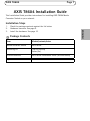
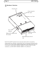
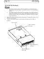
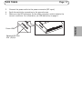
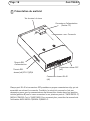
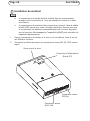
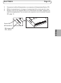
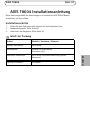
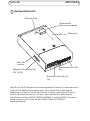
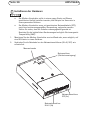
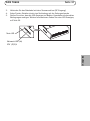
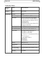
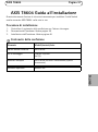
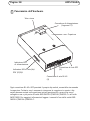
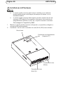
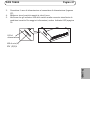
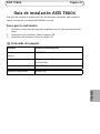
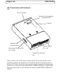
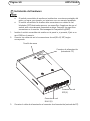
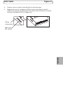
INSTALLATION GUIDE AXIS T8604 Media Converter Switch ENGLISH FRANÇAIS DEUTSCH ITALIANO ESPAÑOL Legal Considerations Video and audio surveillance can be prohibited by laws that vary from country to country. Check the laws in your local region before using this product for surveillance purposes. Electromagnetic Compatibility (EMC) This equipment has been designed and tested to fulfill applicable standards for: • Radio frequency emission when installed according to the instructions and used in its intended environment. • Immunity to electrical and electromagnetic phenomena when installed according to the instructions and used in its intended environment. USA - This equipment has been tested using a shielded network cable and found to comply with the limits for a Class A digital device, pursuant to part 15 of the FCC Rules. These limits are designed to provide reasonable protection against harmful interference when the equipment is operated in a commercial environment. This equipment generates, uses, and can radiate radio frequency energy and, if not installed and used in accordance with the instruction manual, may cause harmful interference to radio communications. Operation of this equipment in a residential area is likely to cause harmful interference in which case the user will be required to correct the interference at his own expense. Canada - This Class A digital apparatus complies with Canadian ICES-003. Europe - This digital equipment fulfills the requirements for RF emission according to the Class A limit of EN 55022. NOTICE! This is a Class A product. In a domestic environment this product may cause RF interference, in which case the user may be required to take adequate measures. This product fulfills the requirements for emissions and immunity according to EN 50121-4 and IEC 62236-4 railway applications. This product fulfills the requirements for immunity according to EN 61000-6-1 residential, commercial and light-industrial environments. This product fulfills the requirements for immunity according to EN 61000-6-2 industrial environments. This product fulfills the requirements for immunity according to EN 55024 office and commercial environments. Australia - This digital equipment fulfills the requirements for RF emission according to the Class A limit of AS/NZS CISPR 22. Korea - ࢇ̛̛Е߶ࡈה$̗ࢷળࢶଢ̛̛Ի۰ શӖЕࡈیЕࢇࢺࡶ࣯ࢂଜ̛ݤԂֲ ɼࢽ࠹ࢂएࠇ߾۰ࡈیଜЕʨࡶּࢶࡳԻଢТЬ Japan - この装置は、クラスA 情報技術装置です。 この装置を家庭環境で使用すると電波妨害 を引き起 こすことがあります。この場合には使用者が適切な 対策を講ずるよう要求され ることがあります。 Safety - This product complies with IEC/EN 60950-1 Safety of Information Technology Equipment. Equipment Modifications - This equipment must be installed and used in strict accordance with the instructions given in the user documentation. This equipment contains no user-serviceable components. Unauthorized equipment changes or modifications will invalidate all applicable regulatory certifications and approvals. Liability - Every care has been taken in the preparation of this document. Please inform your local Axis office of any inaccuracies or omissions. Axis Communications AB cannot be held responsible for any technical or typographical errors and reserves the right to make changes to the product and documentation without prior notice. Axis Communications AB makes no warranty of any kind with regard to the material contained within this document, including, but not limited to, the implied warranties of merchantability and fitness for a particular purpose. Axis Communications AB shall not be liable nor responsible for incidental or consequential damages in connection with the furnishing, performance or use of this material. This product is only to be used for its intended purpose. RoHS - This product complies with both the European RoHS directive, 2002/95/EC, and the Chinese RoHS regulations, ACPEIP. WEEE Directive The European Union has enacted a Directive 2002/96/EC on Waste Electrical and Electronic Equipment (WEEE Directive). This directive is applicable in the European Union member states. The WEEE marking on this product (see right) or its documentation indicates that the product must not be disposed of together with household waste. To prevent possible harm to human health and/or the environment, the product must be disposed of in an approved and environmentally safe recycling process. For further information on how to dispose of this product correctly, contact the product supplier, or the local authority responsible for waste disposal in your area. Business users should contact the product supplier for information on how to dispose of this product correctly. This product should not be mixed with other commercial waste. Support - Should you require any technical assistance, please contact your Axis reseller. If your questions cannot be answered immediately, your reseller will forward your queries through the appropriate channels to ensure a rapid response. If you are connected to the Internet, you can: • download user documentation and software updates • find answers to resolved problems in the FAQ database. Search by product, category, or phrase • report problems to Axis support staff by logging in to your private support area • chat with Axis support staff (selected countries only) • visit Axis Support at www.axis.com/techsup/ Safeguards Please read through this Installation Guide carefully before installing the Axis product. Keep the Installation Guide for further reference. • • • • • • • • Store the Axis product in a dry and ventilated environment. Avoid exposing the Axis product to vibration, shocks or heavy pressure. Do not install the product on unstable brackets, unstable or vibrating surfaces or walls, since this could cause damage to the product. Only use applicable tools when installing the Axis product; excessive force could cause damage to the product. Do not use chemicals, caustic agents, or aerosol cleaners. Use a damp cloth for cleaning. Use only accessories that comply with technical specification of the product. These can be provided by Axis or a third party. Use only spare parts provided by or recommended by Axis. Do not attempt to repair the product by yourself, contact Axis or your Axis reseller for service matters. This Axis product shall be used in compliance with local laws and regulations. To use this Axis product outdoors, it shall be installed in an approved outdoor housing. The Axis product should be installed by a trained professional. Observe relevant national and local regulations for the installation. Transportation • When transporting the Axis product, use the original packaging or equivalent to prevent damage to the product. ENGLISH • • AXIS T8604 Page 7 AXIS T8604 Installation Guide This Installation Guide provides instructions for installing AXIS T8604 Media Converter Switch on your network. Installation Steps Check the package contents against the list below. Hardware overview. See page 8. Install the hardware. See page 10. Package Contents Item Models/variants/notes Media converter switch AXIS T8604 Mounting kit Clip for DIN clip Screw (2x) Printed materials AXIS T8604 Installation Guide (this document) Optional accessories SFP module ENGLISH 1. 2. 3. Page 8 AXIS T8604 Hardware Overview Ground screw Power connector (DC input) Cover Power LED indicator Network connector SFP (2x) Network LED indicator (4x) ETH 1/2/3/4 Network connector RJ-45 (2x) Each RJ-45 and SFP connector has its own dip switch, which is accessed by removing the cover. However, removing the cover is not necessary because the dip switches shall be left in their original positions (position B) unless connecting one or more ports to AXIS Q6032-C/Q6034-C/Q6035-C and AXIS T8605. For more information, see AXIS Q6032-C/Q6034-C/Q6035-C User Manuals. AXIS T8604 Page 9 Connectors Power connector (DC input) - 2-pin terminal block for power input. 1 2 - + Function Notes GND 1 Ground 12 V DC 2 Power in from power supply (sold separately) Specifications Max load = 0.3 A 12 - 13.2 V DC, min 3.5 W Network connector RJ-45 (external) - Two RJ-45 connectors (10Base-T/ 100Base-TX) for network connectivity. Network connector SFP (external) - Two SFP connectors (100Base-FX/1000BaseX) for network connectivity. LED Indicators LED Color Indication Power Unlit DC power unconnected or current protection engaged (power overload). Green DC power connected. Network (4x) Amber 10 Mbit connection. Flashes during activity. Green 100/1000 Mbit connection. Flashes during activity. ENGLISH DC input Pin Page 10 AXIS T8604 Install the Hardware • • 1. 2. The media converter switch shall be installed in an environment protected against dust and water, for example indoors or in an appropriate cabinet. The media converter switch shall be connected using shielded network cables (STP) intended for their specific use. Make sure that the switch is properly grounded. See Electromagnetic Compatibility (EMC) for regulatory requirements. Mount the media converter switch on the wall or, if applicable, attach it to a DIN rail in the cabinet. Connect the network cables to the network connectors (RJ-45, SFP) as required. Ground screw Power connector (DC input) Network connector SFP (2x) Network connector RJ-45 (2x) AXIS T8604 3. 4. 5. Page 11 Connect the power cable to the power connector (DC input). Earth the switch by connecting to the ground screw. Make sure the LED indicators on the media converter switch indicate the correct conditions. For information, see LED Indicators, on page 9. Network LED (4x) ETH 1/2/3/4 ENGLISH Power LED Page 12 AXIS T8604 Technical specifications Function/group Item Specifications Media converter Model switch AXIS T8604 General Casing Metal Power 12–13.2 V DC, max 3.5 W Connectors 2x RJ-45 connectors (10/100 Mbps)* 2x SFP connectors (100/1000 Mbps) for SFP fiber optic modules or SFP to copper modules 1x power *use shielded cables (STP) CAT5 or higher Environment Indoor/cabinet Operating conditions -40 °C to 75 °C (-40 °F to 167 °F) Approvals EN 55022 Class A, EN 61000-3-2, EN 61000-3-3, EN 61000-6-1, EN 61000-6-2, EN 55024 FCC Part 15 Subpart B Class A ICES-003 Class A C-tick AS/NZS CISPR 22 KCC Class A VCCI Class A IEC/EN 60950-1 Weight 284 g (0.63 lb.) Dimensions (HxWxD) 150 x 100 x 30 mm (5.9” x 3.9” x 1.2”) Included Accessories Installation Guide, clip for DIN rail Optional Accessories SFP module AXIS T8604 Page 13 Further Information Visit Axis learning center www.axis.com/academy for useful trainings, webinars, tutorials and guides. Warranty For information about Axis’ product warranty and thereto related information, see www.axis.com/warranty ENGLISH Mesures de sécurité Lisez attentivement le présent Guide d'installation avant d'installer le produit Axis. Conservez le Guide d'installation pour une utilisation ultérieure. • Ce produit Axis doit être utilisé conformément aux lois et réglementations locales en vigueur. • Pour pouvoir être utilisé à l'extérieur, ce produit Axis doit être placé dans un boîtier d'extérieur homologué. • Le produit Axis doit être installé par un professionnel qualifié. Veuillez vous conformer aux règlements nationaux et locaux relatifs à l'installation. Transport • Pour transporter le produit Axis et éviter de l'endommager, utilisez l'emballage d'origine ou un emballage équivalent. FRANÇAIS • Conservez le produit Axis dans un environnement sec et aéré. • Évitez d'exposer le produit Axis aux vibrations, aux chocs ou à une forte pression. N'installez pas le produit sur un support instable, ou des surfaces ou des murs instables ou vibrants, car cela pourrait l'endommager. • N'utilisez que les outils applicables pour installer le produit Axis ; une force excessive pourrait endommager le produit. • Pour le nettoyage, n’utilisez ni produits chimiques, ni substances caustiques ou aérosols. Utilisez un chiffon humide pour le nettoyage. • N’utilisez que des accessoires conformes aux caractéristiques techniques du produit. Ceux-ci peuvent être fournis par Axis ou par un fournisseur tiers. • Utilisez uniquement des pièces de rechange fournies ou recommandées par Axis. • Ne tentez pas de réparer le produit vous-même, contactez Axis ou votre revendeur Axis pour toute réparation. Axis T8604 Page 17 Axis T8604 Guide d'installation Ce Guide d'installation fournit des instructions pour l'installation du Convertisseur de media Axis T8604 sur votre réseau. Procédure d’installation 1. 2. 3. Vérifiez le contenu de l’emballage avec la liste ci-dessous. Aperçu du matériel. Reportez-vous à la section page 18. Installation du matériel. Reportez-vous à la section page 20. Contenu de la boîte Modèles/variantes/remarques Interrupteur de Convertisseur de média Axis T8604 Kit de montage Clip pour le rail DIN Vis (2x) Documentations imprimées Axis T8604 Guide d'installation (ce document) Accessoires en option Module SFP FRANÇAIS Article Page 18 Axis T8604 Présentation du matériel Vis de mise à la terre Connecteur d’alimentation (Entrée CC) Couvercle Témoin DEL d'alimentation Connecteur réseau SFP (x2) Témoin DEL réseau (x4) ETH 1/2/3/4 Connecteur réseau RJ-45 (x2) Chaque port RJ-45 et connecteur SFP possède son propre commutateur dip, qui est accessible en retirant le couvercle. Toutefois, le retrait du couvercle n'est pas nécessaire, parce que les commutateurs dip doivent être laissés dans leur position initiale (position B) sauf si vous connectez un ou plusieurs ports à l' AXIS Q6032-C/ Q6034-C/Q6035-C et à l' AXIS T8605. Pour en savoir plus, consultez les manuels de l'utilisateur AXIS Q6032-C/Q6034-C/Q6035-C. Axis T8604 Page 19 Connecteurs Connecteur d'alimentation (entrée CC) - Prise à 2 broches pour l'entrée de courant. 1 2 - + Fonction Entrée CC Remarques GND (Terre) 1 Mise à la terre 12 V CC 2 Entrée de courant provenant de l'alimentation (vendue séparément) Caractéristiques techniques Charge max = 0.3 A 12 - 13,2 V CC, min 3.5 W Connecteur réseau RJ-45 (externe) - Deux connecteurs RJ-45 (10Base-T/ 100Base-TX) pour la connectivité au réseau. Connecteur réseau SFP (externe) - Deux connecteurs SFP (100Base-FX/ 1000Base-X) pour la connectivité au réseau. Voyants DEL DEL Couleur Indication Alimentation Éteint Alimentation CC déconnectée ou dispositif de protection ampère-métrique activé (surcharge). Vert Alimentation CC connectée Réseau (x4) Orange Connexion 10 Mbit Clignote pendant l'activité. Vert Connexion 100/1000 Mbit Clignote pendant l'activité. FRANÇAIS Broche Page 20 Axis T8604 Installation du matériel • • 1. 2. Le convertisseur de media doit être installé dans un environnement protégé contre la poussière et l'eau, par exemple en intérieur ou dans une armoire. Le convertisseur de media doit être connecté au réseau à l'aide de câbles blindés (STP) prévus pour cette utilisation spécifique. Assurez-vous que le convertisseur de média est convenablement mis à la terre. Reportezvous à la section Electromagnetic Compatibility (EMC) pour connaître les exigences réglementaires. Fixez le convertisseur de media sur le mur ou, le cas échéant, fixez-le sur un rail DIN dans l'armoire. Connectez les câbles de réseau aux connecteurs réseau (RJ-45, SFP) comme requis. Vis de mise à la terre Connecteur d’alimentation (Entrée CC) Connecteur réseau SFP (2x) Connecteur réseau RJ-45 (2x) Axis T8604 3. 4. 5. Page 21 Connectez le câble d'alimentation au connecteur d'alimentation (Entrée CC). Câblez le convertisseur à la terre en le connectant à la vis de mise à la terre. Assurez-vous que les voyants DEL sur le convertisseur de média indiquent les conditions appropriées. Pour en savoir plus, reportez-vous à la section Voyants DEL, page 19. Témoin DEL d'alimentation FRANÇAIS DEL réseau (x4) ETH 1/2/3/4 Page 22 Axis T8604 Caractéristiques techniques Fonction/groupe Article Caractéristiques techniques Interrupteur du Convertisseur de média Modèle Axis T8604 Général Boîtier Métal Alimentation 12-13,2 V CC, max. 3,5 W Connecteurs 2X connecteurs RJ-45 (10/100 Mbits) * 2X connecteurs SFP (100/1000 Mbits) pour modules de fibres optiques SFP ou SFP vers modules cuivre 1 x alimentation * Utilisez des câbles blindés (STP) CAT5 ou supérieur Environnement Intérieur/Armoire Conditions d’utilisation -40 °C à 75 °C (-40 °F à 167 °F) Agréments EN 50022 classe A, EN 61000-3-2, EN 61000-3-3, EN 61000-6-1, EN 610006-2, EN 55024 FCC Partie 15 Sous-partie B Classe A ICES-003 Classe A C-tick AS/NZS CISPR 22 KCC Classe A VCCI Classe A CEI/EN 60950-1 Poids 284 g (0.63 lb.) Dimensions (HxLxP) 150 X 100 x 30 mm (5,9" x 3,9" x 1,2 ") Accessoires inclus Guide d'installation, clip pour rail DIN Accessoires en option Module SFP Axis T8604 Page 23 Plus d’informations Visitez le centre d'apprentissage AXIS sur www.axis.com/academy pour des formations utiles, des webinars, des tutoriels et des guides. Garantie Pour plus d'informations à propos de la garantie du produit Axis et des information s'y rapportant, voir www.axis.com/warranty FRANÇAIS Sicherheitsvorkehrungen Bitte lesen Sie diese Installationsanleitung sorgfältig durch, bevor Sie mit der Installation des Axis Produkts beginnen. Halten Sie die Installationsanleitung bereit, falls Sie darauf zurückgreifen müssen. • Verwenden Sie dieses Axis-Produkt unter Beachtung der vor Ort geltenden rechtlichen Bestimmungen. • Um dieses Axis-Produkt im Freien verwenden zu können, muss es in einem zugelassenen Außengehäuse installiert werden. • Das Axis Produkt sollte nur von geschultem Fachpersonal installiert werden. Beachten Sie bei der Montage die geltenden nationalen und lokalen Bestimmungen. Transport • Transportieren Sie das Axis-Produkt nur in der Originalverpackung bzw. in einer vergleichbaren Verpackung, damit das Produkt nicht beschädigt wird. DEUTSCH • Lagern Sie das Axis-Produkt in einer trockenen und belüfteten Umgebung. • Setzen Sie das Axis Produkt keinen Vibrationen, Erschütterungen oder starkem Druck aus. Installieren Sie das Produkt nicht an instabilen Halterungen oder instabilen oder vibrierenden Oberflächen oder Mauern, da dadurch das Produkt beschädigt werden könnte. • Verwenden Sie bei der Installation des Axis Produkts nur geeignetes Werkzeug; zu hoher Kraftaufwand kann das Produkt beschädigen. • Verwenden Sie keine chemischen, ätzenden oder aerosolhaltigen Reinigungsmittel. Verwenden Sie zur Reinigung ein feuchtes Tuch. • Verwenden Sie nur Zubehör, das den technischen Spezifikationen des Produkts entspricht. Dieses ist von Axis oder Drittanbietern erhältlich. • Verwenden Sie nur Ersatzteile, die von Axis empfohlen bzw. bereitgestellt wurden. • Versuchen Sie nicht, das Produkt selbst zu reparieren. Wenden Sie sich bei Service-Angelegenheiten an Axis oder an Ihren Axis-Händler. AXIS T8604 Seite 27 AXIS T8604 Installationsanleitung Diese Anleitung enthält die Anweisungen zur Installation AXIS T8604 MedienUmschalter auf Ihrem Netz. Installationsschritte 1. 2. 3. Prüfen Sie den Packungsinhalt anhand der nachfolgenden Liste. Hardwareübersicht. Siehe Seite 28. Installieren der Hardware. Siehe Seite 30. Inhalt der Packung Modelle / Varianten / Hinweise Medien-Umschalter AXIS T8604 Montagesatz Klemme für DIN Klemme Schrauben (2x) Gedruckte Dokumente AXIS T8604 Installationsanleitung (dieses Dokument) Optionales Zubehör SFP Modul DEUTSCH Artikel Seite 28 AXIS T8604 Hardwareübersicht Masseschraube Netzanschluss (Gleichstromeingang) Abdeckung Netz-LED Anzeige Netzwerk-LED-Anzeige (4x) ETH 1/2/3/4 Netzwerkanschluss SPF (2x) Netzwerkanschluss RJ-45 (2x) Jeder RJ-45 und SFP Anschluss hat seinen eigenen Dip-Schalter, auf den man durch Entfernen der Abdeckung zugreifen kann. Es ist jedoch nicht notwendig die Abdeckung zu entfernen, da der Dip-Schalter in seiner ursprünglichen Position (Position B) verbleiben sollte, es sei denn, man verbindet eine oder mehrere Schnittstellen mit Axis Q6032-C/Q6034-C/Q6035-C und Axis T8605. Für weitere Informationen lesen Sie bitte das Axis Q6032-C/Q6034-C/Q6035-C Benutzerhandbuch. AXIS T8604 Seite 29 Anschlüsse Netzanschluss (Gleichstromeingang) - 2-polige Klemmenleiste für Stromeingang. 1 2 - + Funktion Pol Hinweise Gleichstrom- Masse eingang (GND) 1 Masse 2 Stromeingang von Stromquelle (separat angeboten) 12 V DC Spezifikationen Max. Stromstärke = 0.3 A 12–13,2 V Gleichstrom, min 3.5 W Netzwerkanschluss RJ-45 (extern) - Zwei RJ-45 Anschlüsse (10Base-T/100BaseTX) für Netzwerkanschluss. LED-Anzeigen LED Farbe Bedeutung Netzspannung Leuchtet Gleichstrom nicht angeschlossen oder nicht Fehlerstromschutz aktiviert (Überlastung). Grün Gleichstrom angeschlossen. Netzwerk (4x) Gelb 10-Mbit-Anschluss. Blinkt wenn aktiv. Grün 100/1000-Mbit-Anschluss. Blinkt wenn aktiv. DEUTSCH Netzwerkanschluss SFP (extern) - Zwei SFP-Anschlüsse (100Base-FX/1000BaseX) für Netzwerkanschluss. Seite 30 AXIS T8604 Installieren der Hardware • • 1. 2. Der Medien-Umschalter sollte in einem gegen Staub und Wasser geschützten Umfeld installiert werden, zum Beispiel im Haus oder in einem passenden Gehäuse. Der Medien-Umschalter muss mit geschirmten Netzwerkkabeln (STP), nach ihrer bestimmungsgemäßen Verwendung, verbunden werden. Stellen Sie sicher, dass der Schalter ordnungsgemäß geerdet ist. Beachten Sie die behördlichen Bestimmungen bezüglich Electromagnetic Compatibility (EMC). Montieren Sie den Medien-Umschalter an eine Wand oder, wenn möglich, auf eine DIN Leiste in einem Gehäuse. Verbinden Sie die Netzkabel zu den Netzwerkanschlüssen (RJ-45, SFP) wie erforderlich. Masseschraube Netzanschluss (Gleichstromeingang) Netzwerkanschluss SFP (2x) Netzwerkanschluss RJ-45 (2x) AXIS T8604 3. 4. 5. Seite 31 Verbinden Sie das Netzkabel mit dem Stromanschluss (DC Eingang). Erden Sie den Schalter durch eine Verbindung mit der Erdungsschraube. Stellen Sie sicher, dass die LED-Anzeigen im Medien-Umschalter die korrekten Bedingungen anzeigen. Weitere Informationen finden Sie unter LED-Anzeigen, auf Seite 29. Netz-LED Netzwerk LED (4x) ETH 1/2/3/4 DEUTSCH Seite 32 AXIS T8604 Technische Daten Funktion/ Gruppe Artikel Spezifikationen MedienUmschalter Modell AXIS T8604 Allgemeines Gehäuse Metall Netzspannung 12–13.2 V DC, Max. 3,5 W Anschlüsse 2x RJ-45 Anschlüsse (10/100 Mbps)* 2x SFP Anschlüsse (100/1000 Mbps) für die SFP faseroptischen Module oder SFP zu Kupfermodule 1x Netzspannung *Gebrauch von geschirmten Kabeln (STP) Kategorie 5 oder höher Umgebung Innen/Gehäuse Betriebsbedingungen -40 °C bis 75 °C (-40 °F bis 167 °F) Zulassungen EN 55022 Klasse A, EN 61000-3-2, EN 61000-3-3, EN 61000-6-1, EN 61000-6-2, EN 55024 FCC Abschnitt 15 Unterabschnitt B Klasse A ICES-003 Klasse A C-tick AS/NZS CISPR 22 KCC Klasse A VCCI Klasse A IEC/EN 60950-1 Gewicht 284 g (0.63 lb.) Abmessungen (HxBxT) 150 x 100 x 30 mm (5.9” x 3.9” x 1.2”) Im Lieferumfang enthaltenes Zubehör Installationsanleitung, Klemme für DIN Leiste Optionale Zubehörteile SFP Modul AXIS T8604 Seite 33 Weitere Informationen Im Axis Lernzentrum unter www.axis.com/academy finden Sie hilfreiche Schulungen, Webinare, Lernprogramme und Anleitungen. Garantie Informationen zur Axis Produktgarantie finden Sie unter www.axis.com/warranty DEUTSCH Sicurezza Leggere attentamente questa Guida all'installazione prima di installare un prodotto Axis. Conservare la Guida all'installazione per future consultazioni. • Conservare il prodotto Axis in un ambiente asciutto e ben ventilato. • Evitare di esporre il prodotto Axis alle vibrazioni, agli urti o a forte pressione. Non installare il prodotto su staffe instabili, superfici o pareti instabili o vibranti, poiché ciò potrebbe danneggiare il prodotto. • Utilizzare solo strumenti idonei quando si installa il prodotto Axis. Una forza eccessiva potrebbe danneggiare il prodotto. • Non utilizzare sostanze chimiche, agenti caustici o detergenti spray. Utilizzare un panno umido per la pulizia. • Utilizzare solo accessori conformi alle specifiche tecniche del prodotto. Queste possono essere fornite da Axis o da terze parti. • Utilizzare solo parti di ricambio fornite o raccomandate da Axis. • Non tentare di riparare il prodotto da soli, contattare Axis o il rivenditore di zona Axis per assistenza. Trasporto • Quando si trasporta il prodotto Axis, utilizzare l'imballo originale o un imballo equivalente per evitare di danneggiare il prodotto. ITALIANO • Questo prodotto Axis deve essere utilizzato in conformità alle leggi e alle disposizioni locali. • Per utilizzare questo prodotto Axis all'esterno, è necessario installarlo in un alloggiamento per esterni approvato. • Il prodotto Axis deve essere installato da un tecnico qualificato. Osservare le disposizioni nazionali e locali per l'installazione. AXIS T8604 Pagina 37 AXIS T8604 Guida all'installazione Questo documento fornisce le istruzioni necessarie per installare l'unità Switch media converter AXIS T8604 nella rete in uso. Procedura di installazione 1. 2. 3. Controllare il contenuto della confezione con l'elenco che segue. Panoramica dell’hardware. Vedere pagina 38. Installazione dell’hardware. Vedere pagina 40. Contenuto della confezione Elemento Modelli/varianti/note Switch media converter AXIS T8604 Kit di montaggio Clip per clip DIN Viti (2) Materiali stampati AXIS T8604 Guida all'installazione (questo documento) Accessori opzionali Modulo SFP ITALIANO Pagina 38 AXIS T8604 Panoramica dell'hardware Vite a terra Connettore di alimentazione (Ingresso CC) Copertura Indicatore LED di alimentazione Connettore di rete SPF (2) Indicatore LED di rete (4x) ETH 1/2/3/4 Connettore di rete RJ-45 (2) Ogni connettore RJ-45 e SFP possiede il proprio dip switch, accessibile rimuovendo la copertura. Tuttavia, non è necessario rimuovere la copertura in quanto i dip switch devono restare nelle posizione iniziali (posizione B) a meno che non si colleghino una o più porte all'unità AXIS Q6032-C/Q6034-C/Q6035-C e all'unità AXIS T8605. Per maggiori informazioni leggere i manuali d'uso delle unità AXIS Q6032-C/Q6034-C/Q6035-C. AXIS T8604 Pagina 39 Connettori Morsettiera di alimentazione (ingresso CC) - Morsettiera di alimentazione a 2 pin per ingresso alimentazione. 1 2 - + Funzione Ingresso CC Pin Note GND 1 Terra 12 V CC 2 Alimentazione dall'alimentatore (venduto separatamente) Specifiche Carico max = 0,3 A 12 - 13,2 V CC, min 3,5 W Connettore di rete RJ-45 (esterno) - Due connettori RJ-45 (10Base-T/100BaseTX) per connettività di rete. Connettore di rete SFP (esterno) - Due connettori SFP (100Base-FX/1000Base-X) per connettività di rete. Indicatori LED Colore Indicazione Alimentazione Spento Alimentazione CC non connessa o protezione della corrente attivata (sovraccarico di alimentazione). Verde Connesso all'alimentazione CC. Rete (4) Giallo Connessione 10 Mbit. Lampeggia durante l'attività Verde Connessione 100/1000 Mbit. Lampeggia durante l'attività ITALIANO LED Pagina 40 AXIS T8604 Installazione dell'hardware • • 1. 2. Lo switch media converter dovrà essere installato in un ambiente protetto dalla polvere e dall'acqua, ad esempio all'interno o in un armadietto adatto. Lo switch media converter dovrà essere connesso usando cavi di rete schermati (STP) adatti all'uso specifico. Assicurarsi che lo switch sia adeguatamente connesso a terra. Per i requisiti normativi consultare Electromagnetic Compatibility (EMC). Montare lo switch media converter sulla parete o, se possibile, collegarlo a una guida DIN nell'armadietto. Connettere i cavi di rete ai connettori di rete (RJ-45, SFP) come richiesto. Vite di terra Connettore di alimentazione (Ingresso CC) Connettore di rete SFP (2) Connettore di rete RJ-45 (2) AXIS T8604 3. 4. 5. Pagina 41 Connettere il cavo di alimentazione al connettore di alimentazione (ingresso CC). Mettere a terra lo switch usando la vite di terra. Verificare che gli indicatori LED dello switch media converter visualizzino le condizioni corrette. Per maggiori informazioni, vedere Indicatori LED, a pagina 39 LED di alimentazione LED di rete (4) ETH 1/2/3/4 ITALIANO Pagina 42 AXIS T8604 Specifiche tecniche Funzione/ gruppo Elemento Specifiche Switch media converter Modello AXIS T8604 Caratteristiche generali Involucro Metallo Alimentazione 12-13,2 V CC, max 3,5 W Connettori 2 Connettori RJ-45 (10/100 Mbps)* 2 Connettori SFP (100/1000 Mbps) per moduli SFP a fibra ottica o moduli SFP in rame 1 alimentatore *usare cavi schermati (STP) CAT5 o maggiori Ambiente Interno/armadietto Condizioni operative -40 °C a 75 °C (-40 °F a 167 °F) Approvazioni EN 55022 Classe A, EN 61000-3-2, EN 61000-3-3, EN 61000-6-1, EN 61000-6-2, EN 55024 FCC Parte 15 Sezione B Classe A ICES-003 Classe A Contrassegno AS/NZS CISPR 22 KCC Classe A VCCI Classe A IEC/EN 60950-1 Peso 284 g (0,63 lb.) Dimensioni (HxLxP) 150 x 100 x 30 mm (5,9” x 3,9” x 1,2”) Accessori inclusi Manuale d'installazione, clip per guida DIN Accessori opzionali Modulo SFP AXIS T8604 Pagina 43 Ulteriori informazioni Per utili corsi di formazione, webinar, tutorial e guide, visitare il centro di apprendimento di Axis all'indirizzo www.axis.com/academy. Garanzia Per informazioni sulla garanzia del prodotto Axis e le relative informazioni, visitare il sito www.axis.com/warranty ITALIANO Medidas preventivas Lea detenidamente esta Guía de instalación antes de instalar el producto Axis. Guarde la Guía de instalación para poder consultarla en el futuro. • Guarde el producto Axis en un entorno seco y ventilado. • Evite exponer el producto Axis a vibraciones, golpes o presiones excesivas. No instale el producto en soportes inestables ni en superficies o paredes inestables o con vibraciones, ya que esto podría dañarlo. • Utilice solo las herramientas apropiadas para instalar el producto Axis; una fuerza excesiva podría dañarlo. • No utilice productos químicos, agentes cáusticos ni limpiadores en aerosol. Límpielo con un paño húmedo. • Utilice solo accesorios que cumplan las especificaciones técnicas del producto. Puede obtenerlos de Axis o de un tercero. • Utilice solo piezas de recambio suministradas o recomendadas por Axis. • No intente reparar el producto usted mismo, póngase en contacto con Axis o con el distribuidor de Axis para los temas de servicio técnico. • Este producto Axis se utilizará de conformidad con la legislación y normativas locales. • Para utilizar este producto Axis en exteriores, se instalará en una carcasa protectora para exteriores aprobada. • La instalación del producto Axis debe realizarla un profesional cualificado. Siga las normativas nacionales y locales aplicables para la instalación. Transporte ESPAÑOL • A la hora de transportar el producto Axis, utilice el embalaje original o uno equivalente para no dañar el producto. AXIS T8604 Página 47 Guía de instalación AXIS T8604 Esta guía de instalación proporciona las instrucciones necesarias para instalar el switch convertidor de medios AXIS T8604 en su red. Pasos para la instalación 1. 2. 3. Verifique el contenido del paquete cotejándolo con la lista que aparece más abajo. Presentación del hardware. Véase la página 48. Instalación del hardware. Véase la página 50. Contenido del paquete Artículo Modelos/variantes/notas Switch convertidor de medios AXIS T8604 Kit de montaje Clip para el clip DIN Tornillos (2x) Materiales impresos AXIS T8604 Guía de instalación (este documento) Accesorios opcionales Módulo SFP ESPAÑOL Página 48 AXIS T8604 Presentación del hardware Tornillo de masa Conector de alimentación (entrada de CC) Cubierta Indicador LED de alimentación Indicadores LED de red (4) ETH 1/2/3/4 Conector de red SFP (2x) Conector de red RJ-45 (2x) Cada conector RJ-45 y SFP tiene su propio switch DIP y puede acceder a éste quitando la cubierta. No obstante, no es necesario quitar la cubierta ya que los switches DIP deben mantenerse en su posición original (posición B) a menos que conecte uno o más puertos para AXIS Q6032-C/Q6034-C/Q6035-C y AXIS T8605. Para más información, vea los manuales de usuario de AXIS Q6032-C/Q6034-C/ Q6035-C. AXIS T8604 Página 49 Conectores Conector de alimentación (entrada de CC) - Bloque de terminales de 2 pines para la entrada de alimentación. 1 2 - + Función Pines Notas Entrada CC Masa 12 V CC 1 Masa 2 Entrada de alimentación desde fuente de alimentación (se vende por separado) Especificaciones Carga máx. = 0,3 A 12 - 13,2 V CC, mín. 3,5 W Conector de red RJ-45 (externo) - Dos conectores RJ-45 (10Base-T/100Base-TX) para conectividad de red. Conector de red SFP (externo) - Dos conectores SFP (100Base-FX/1000Base-X) para conectividad de red. Indicadores LED LED Color Alimentación Apagado Alimentación de CC no conectada o protección de corriente aplicada (sobrecarga de alimentación). Verde Alimentación de CC conectada. Ámbar Conexión de 10 Mbits. Parpadea para indicar actividad. Verde Conexión de 100/1000 Mbits. Parpadea para indicar actividad. ESPAÑOL Red (4) Indicación Página 50 AXIS T8604 Instalación del hardware • • 1. 2. El switch convertidor de medios se instalará en un entorno protegido del polvo y el agua, por ejemplo, en interiores o en un armario apropiado. El switch convertidor de medios debe conectarse con cables de red blindados (STP) destinados para su uso específico. Asegúrese de que el switch esté correctamente conectado a masa. Consulte los requisitos normativos en la sección Electromagnetic Compatibility (EMC). Instale el switch convertidor de medios en la pared o, si procede, fíjelo a un carril DIN en el armario. Conecte los cables de red a los conectores de red (RJ-45, SFP) según corresponda. Tornillo de masa Conector de alimentación (entrada de CC) Conector de red SFP (2) Conector de red RJ-45 (2) 3. Conecte el cable de alimentación al conector de alimentación (entrada de CC). AXIS T8604 4. 5. Página 51 Conecte a tierra el switch conectándolo al tornillo de masa. Asegúrese de que los indicadores LED del switch convertidor de medios indiquen las condiciones adecuadas. Para obtener más información, consulte la sección Indicadores LED, en la página 49. LED de alimentación LED de red (4) ETH 1/2/3/4 ESPAÑOL Página 52 AXIS T8604 Especificaciones técnicas Función/Grupo Artículo Especificaciones Switch convertidor de medios Modelo AXIS T8604 Generales Carcasa Metálica Alimentación 12-13,2 V CC, máx. 3,5 W Conectores 2 conectores RJ-45 (10/100 Mbps)* 2 conectores SFP (100/1000 Mbps) para los módulos SFP de fibra óptica o SFP para módulos de cobre 1 alimentación *use cables blindados (STP) CAT5 o superior Entorno Interior/armario Condiciones de funcionamiento -40 °C a 75 °C (-40 °F a 167 °F) Homologaciones EN 55022 Clase A, EN 61000-3-2, EN 61000-3-3, EN 61000-6-1, EN 61000-6-2, EN 55024 FCC Parte 15 Subparte B Clase A ICES-003 Clase A C-tick AS/NZS CISPR 22 KCC Clase A VCCI Clase A IEC/EN 60950-1 Peso 284 g (0,63 lb) Dimensiones (Alt. x Anch. x Prof.) 150 x 100 x 30 mm (5,9” x 3,9” x 1,2”) Accesorios incluidos Guía de instalación, clip para el riel DIN Accesorios opcionales Módulo SFP AXIS T8604 Página 53 Más información Visite el centro de formación de Axis en www.axis.com/academy para consultar cursos, seminarios web, tutoriales y guías. Garantía Para obtener información acerca de la garantía del producto de Axis e información relacionada, vea www.axis.com/warranty ESPAÑOL Installation Guide AXIS T8604 © Axis Communications AB, 2012 Ver.1.1 Printed: October 2012 Part No. 49186