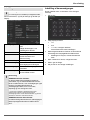
1
System operation
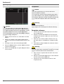
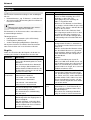
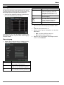
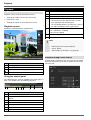
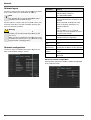
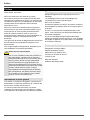
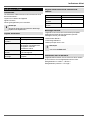
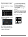
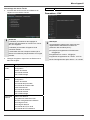
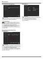
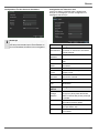
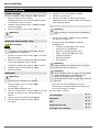
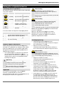
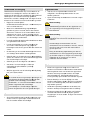
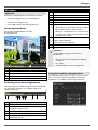
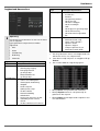
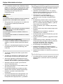
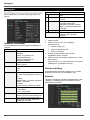
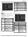
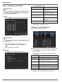
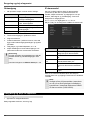
Connections on the rear of the device
No.
8
Note
Note
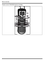
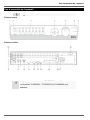
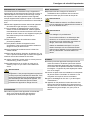
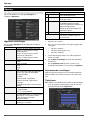
Pay attention to the overview on page 3.
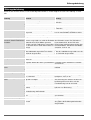
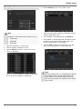
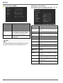
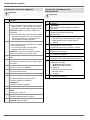
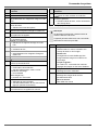
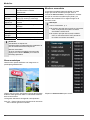
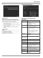
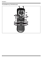
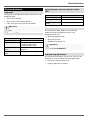
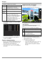
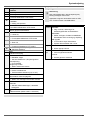
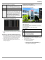
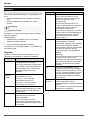
Pay attention to the remote control diagram on
page 4.
Name
Function
VIDEO SPOT OUT: BNC video output
•
When using a HDMI/VGA monitor:
No video signal is displayed.
When using no HDMI/VGA monitor:
The video spot signal is displayed..
AUDIO SPOT OUT: Cinch audio output
•
9
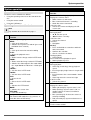
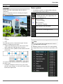
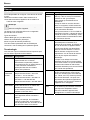
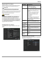
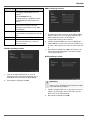
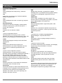
Operating elements on the remote control
MAIN: BNC video output
No.
21
22
23
•
When using a HDMI/VGA monitor:
Video spot signal is displayed.
24
•
When using no VGA monitor:
The main video signal is displayed.
25
AUDIO OUT: Cinch audio output (synchronised
with video output)
26
10
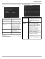
LINE IN 1, 2: Cinch audio input
27
11
VGA:
VGA monitor connection (9-pin), video output
signal
RS-232:
•
12
•
Serial port – no functionality
13
HDMI
14
•
HDMI monitor connection
LAN:
15
•
Ethernet LAN connection
USB port
16
ALARM IN:
•
RS-485 connection for PTZ cameras
•
Max. 16 alarm inputs
ALARM OUT:
17
•
Max. 4 relay outputs
Connection for earthing line
18
Power switch and mains power connection:
19
•
100–240 V AC, 50–60 Hz
LOOP OUT: Connection for looped video signals
(cable available separately)
20
VIDEO IN: BNC inputs
AUDIO IN: Cinch inputs
Note
All audio inputs have no audio amplifier -> the audio signal has to be amplified before connected.
Therefore you can use a microphone amplifier.
14
28
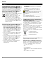
Name
Function
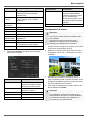
DEV:
Assigns the remote control with the device ID
Alphanumeric keys:
• Selects the camera (channel) in the live view
• Entry of letters and digits in system fields
A:
Changes the entry format (upper / lower case,
symbols, digits)
PLAY:
Starts playback
VOIP
• Not used
PREV:
Changes the screen display in the live view
Navigation keys:
During playback:
• , Sets the speed
• ⊳, Previous / next day
In the live view:
• Selects the camera (channel selection)
In menus:
• Navigation
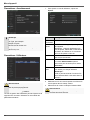
ESC:
• Not used