1
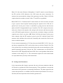
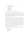
Jussi Rantoja AVR UPGRADES Technology and Communication 2014 VAASAN AMMATTIKORKEAKOULU Sähkötekniikan koulutusohjelma TIIVISTELMÄ Tekijä Opinnäytetyön nimi Vuosi Kieli Sivumäärä Ohjaaja Jussi Rantoja AVR Upgrades 2014 englanti 36 Vesa Verkkonen Wärtsilän installaatioissa on yhä käytössä vanhoja automaattisia jännitteensäätäjiä (AVR), joita ei enää ole saatavilla. Nämä vanhentuneet jännitteensäätäjät tullaan ennemmin tai myöhemmin korvaamaan uusilla. Opinnäytetyön tarkoituksena oli luoda ohjeistus päivitysprosessin tueksi. Ohjeistuksen teko aloitettiin tutustumalla aiheeseen ja perehtymällä AVR:n toimintaan manuaalien, piirustusten ja muun aiheeseen liittyvän materiaalin avulla. Aiheen ymmärtämiseksi tuli myös tutustua generaattorin sekä sitä pyörittävän moottorin toimintaan eri kuormitustilanteissa. Työ oli pitkälti selvitysluontoista ja siinä tutkittiin mitä ominaisuuksia uusi AVR tarjoaa ja mitä mahdollisuuksia olisi vielä käyttämättä. Työ sisälsi myös runsaasti Ethernet-liitynnän kautta tapahtuvaan Modbus-protokollapohjaisen kommunikoinnin tarjoamiin ominaisuuksiin ja mahdollisuuksiin perehtymistä. Lopputuloksena syntyi ohjeistus, jossa on esitetty päivitysprosessin kannalta oleellisimmat asiat kuten päivitysprosessissa tarvittavat tiedot alkuperäisestä installaatiosta, eroavaisuudet kytkennöissä ja toiminnallisuuksissa sekä uuden laitteen parametrien asettelu. Lisäksi ohjeistuksessa on esitelty uuden laitteen tarjoamia ominaisuuksia, joita voidaan mahdollisesti ottaa käyttöön päivityksen myötä. Avainsanat ohjeistus, automaattinen jännitteensäätäjä, päivitys, Modbus-protokolla VAASAN AMMATTIKORKEAKOULU UNIVERSITY OF APPLIED SCIENCES Sähkötekniikan koulutusohjelma ABSTRACT Author Title Year Language Pages Name of Supervisor Jussi Rantoja AVR Upgrades 2014 English 36 Vesa Verkkonen The obsolete automatic voltage regulators (AVR) are still being used in several Wärtsilä installations. Because of the old AVRs are not available anymore, they will be replaced with the new model sooner or later. The purpose of this thesis was to create the work instructions for the upcoming upgrade projects. The making of the instructions was started by getting familiar with the subject and the functionality of the AVR by reading the manuals and analyzing drawings. To understand the subject, getting familiar with the operation modes of the generator and the engine was also required. The thesis included largely sorting out which features of the new AVR has already taken and which features could possibly be taken into use. The thesis also included studying the features and possibilities provided by the Modbus protocol based communication over the Ethernet interface. As a result the work instructions were created. The instructions represents the most essential points such as required information from the original installation, the functional and connection differences caused by the upgrade and the setting the parameters for the new AVR. Keywords Instructions, automatic voltage regulator, operation mode, Modbus communication CONTENTS TIIVISTELMÄ ABSTRACT 1 INTRODUCTION ............................................................................................ 7 1.1 Wärtsilä ..................................................................................................... 7 1.2 Employer ................................................................................................... 7 1.3 Purpose of the Thesis ................................................................................ 8 2 THEORETICAL BACKROUND .................................................................... 9 2.1 Synchronous Generator ............................................................................. 9 2.1.1 Stator ........................................................................................... 10 2.1.2 Rotor............................................................................................ 10 2.1.3 Brushless Excitation .................................................................... 11 2.1.4 Excitation Power Supplies .......................................................... 12 2.2 AVR ........................................................................................................ 13 2.3 Operation of the Generating Set ............................................................. 14 2.4 Engine Operation Modes ........................................................................ 16 2.4.1 Speed Droop Control .................................................................. 16 2.4.2 Isochronous Load Sharing........................................................... 18 2.4.3 kW Control .................................................................................. 19 2.5 Generator Operating Modes .................................................................... 19 2.5.1 Voltage Droop ............................................................................. 19 2.5.2 Voltage Droop Compensation And Cross Current Compensation 19 2.5.3 Power Factor And var Control .................................................... 20 4 BACKGROUND ............................................................................................ 21 4.1 ABB Unitrol 1020 ................................................................................... 21 4.2 Purpose of the Instructions...................................................................... 22 4.3 Making of the Instructions ...................................................................... 23 4.4 Testing..................................................................................................... 23 5 CONTENTS OF THE INSTRUCTIONS ...................................................... 25 5.1 Initial Information ................................................................................... 25 5.2 Basic Setup And the New Setup ............................................................. 26 5.3 Settings And Parameters ......................................................................... 27 5.4 New Functions And Features of the ABB Unitrol 1020 ......................... 29 5.4.1 CMT 1000 ................................................................................... 29 5.4.2 Ethernet Interface / Modbus Communication ............................. 30 5.4.3 Time Synchronization ................................................................. 31 5.4.4 Rotating Diode Monitoring (RDM) ............................................ 31 5.4.5 Limiters ....................................................................................... 32 6 CONCLUSION .............................................................................................. 33 REFERENCES...................................................................................................... 35 6 LIST OF FIGURES Figure 1. Stator steel plates p. 10 Figure 2. Cylindrical (left) and salient pole rotors p. 11 Figure 3. Block diagram of the simple basic AVR p. 14 Figure 4. Power triangle p. 15 Figure 5. Speed droop p. 17 Figure 6. 100 % and 50 % loads at 3 % droop setting p. 18 Figure 7. ABB Unitrol 1020 p. 22 7 1 INTRODUCTION 1.1 Wärtsilä Wärtsilä is a global provider of the power solutions for the marine and energy applications. The company has approximately 18 700 employees in nearly 70 countries around the globe. In 2013 Wärtsilä net sales totaled 4,7 billion Euros. Wärtsilä is divided into three different units: Ship power, Power plants and Services. Ship power acts in the field of marine, oil and gas. In 2013 the net sales of Ship power was 1325 million Euros. Along with the engines, Ship power supplies for example propulsion equipment, control systems and sealing solutions. Power plants supplies power plants up to 600 MW (megawatts). Plants are for several purposes: peaking, reserve, industrial self-generation and load-following. The product range covers also LNG (liquefied natural gas) terminals and distribution systems. In 2013 its net sales was 1459 million Euros. Services are providing lifecycle support for Wärtsilä installations by providing maintenance, service, reconditioning as well as efficiency and performance optimizing and customer training. The Services has a global service network for both, power plant and marine installations. In 2013 Services net sales was 1842 million Euros. /27/ 1.2 Employer This thesis was made in 2014 for Plant Automation, which is a part of Technical Service. It is a proactive organization which supports Wärtsilä and its customers in technical issues regarding the secondary controls in the field of electrical and automation. It continuously maintains, refreshes and develops its technical knowledge, and aims to improve the ways of distributing the knowledge for those who need it. 8 The job of the Plant automation is to make field tests, site surveys and to arrange trainings. It also handles the technical requests, software backups and distribution of the plant automation related software development tools. /26/ 1.3 Purpose of the Thesis The purpose of the thesis was to create the instructions for the AVR upgrade projects. The main target of the instructions was a replacement of an obsolete Basler DECS 125-15 type AVRs with the new ABB Unitrol 1020. To the customer it will be more economical to update the legacy AVRs to the new and secure the spare part availability before the old AVRs will break. It will of course ease the work of Wärtsilä as the replacement solutions could be offered and realized systematically at the same time. The output of the project, the work instructions are meant to support the whole replacement project all the way from the sales to design and commissioning. 9 2 THEORETICAL BACKROUND 2.1 Synchronous Generator The generating set comprises a diesel or gas engine and a generator. The engine is a prime mover which produces a mechanical energy that rotates the generator connected to the engine. For example in 50 Hz system the Wärtsilä 16V34DF engine is rotating 750 rpm and it produces rated power of 7200 kW to the generator which produces electrical power of 6920 kW. /28/ Electric generators are rotating machines that convert mechanical energy to electrical energy. Mechanical energy comes down from a prime mover. The prime mover is a device, for example a steam turbine or in this case, a diesel or gas engine connected to the generator shaft and thus rotating it to produce electricity. Synchronous machine is a device whose rotor is rotating at the same speed as the rotating magnetic field. For comparison, in asynchronous machines the rotor and the magnetic field are rotating with different speeds. /4, 7/ The frequency of the generator is depending on the rotating speed and the number of the poles of the generator which can be seen from the next equation: ݂= (1) where f is the frequency of the induced voltage, p is a number of the pairs of poles on the rotor and n is speed of the rotor. The constant 60 converts rpm to revolutions per second. If the engine is rotating at 750 rpm in the 50 Hz system the number of the pairs of the poles can be calculated by solving the p as follows: = ∗ (2) By placing the given frequency and speed to the equation the number of the pairs of poles is 4 which is received as a result. /10/ 10 2.1.1 Stator In the synchronous generator there are two main parts. The stationary tationary part is called the stator and inside the stator is the rotating part of the generator, called the rotor. The stator is constructed by laminating thick insulated steel plates tot gether (Figure 1). ). This kind of construction minimizes the losses caused by eddy currents. Figure 1. Stator steel plates /18/ As shown inn Figure 1 there are slots on the inner circumference of the stator plate. The 3-phase phase armature winding winding is wound inside these slots. The stator windings are further on connected to the generator terminals. /14/ 2.1.2 Rotor The rotor otor is the rotating part of the generator and it is built on the shaft. The synchronous machine has two different rotor types, cylindrical cal and salient pole (Fig(Fi ure 2). 11 Figure 2. Cylindrical (left) and salient pole rotors /5/ Generators with the cylindrical rotors are typically used with higher speeds, 1500 rpm and above. A typical application for cylindrical rotors is a steam turbine. The diameter of the cylindrical rotor is smaller due to mechanical forces caused by the higher speed. Salient pole rotors are used in the lower speed applications, such as hydroelectric power plants and diesel- or gas-powered medium- and slow-speed engines. The rotor is constructed from the laminated plates, just like the stator, to reduce the eddy current losses. The salient pole rotor has the T-shaped poles. The field winding or excitation winding is wound around the poles of the rotor. Direct current (DC) is supplied to the rotor field windings with different polarity on the North (N) and South (S) poles (Figure 2). The current in the field windings creates a flux. When that flux rotates according to the rotor, it induces sinusoidal 3-phase voltage to the stator windings. /14/ 2.1.3 Brushless Excitation In the conventional excitation system the exciting current is supplied to the excitation windings with the coal brushes and slip rings. Coal brushes, slip rings and commutators of the DC excitation system require maintenance which is eliminated by brushless excitation. 12 Brushless excitation is based on a small AC (Alternating Current) generator mounted on the generator shaft. Compared to the main generator, the construction of the exciter is inversed. The DC field current is supplied to the stator creating a static flux. When the shaft is rotating it induces 3-phase AC voltage to the armature windings that are rotating in the rotor of the exciter. This alternating current is then rectified by the diode bridge and supplied to the field windings of the main generator. /19/ 2.1.4 Excitation Power Supplies The permanent magnet generator (PMG) is an independent generator mounted on the generator shaft to produce excitation power when the generator is rotating. The PMG excitation power supply gives a reliable voltage build-up on starting situations. Because the PMG is not affected by the load circuits of the generator, it gives the same excitation power even in short circuit situations where the generator voltage drops near to zero. Excitation from a potential source takes the excitation power from the potential transformers on the generator output. This kind of excitation supply is depending on the generator voltage and it requires a separate supply for the short circuit situations. This short circuit excitation is taken from appropriate boost current transformers to maintain the sufficient excitation when the generator voltage drops. With this kind of excitation system the voltage build-up is dependent on a residual voltage. If there is not enough residual voltage to build up the voltage, the generator must be excited with a separate battery or by using field flashing. The field flashing is the function of the voltage regulator for exciting the machine with no residual voltage. Auxiliary windings are wound into the same slots as the armature winding but it has mounted in a different way to work more like a current transformer. Like the PMG, the auxiliary windings are producing sufficient excitation power under 13 short circuit situations. However, the voltage build-up also requires the residual voltage. /14/ 2.2 AVR AVR (Automatic Voltage Regulator) is a device controlling the excitation current of the synchronous generator and therefore the output voltage of the generator. It keeps the generator operation inside the allowed limits, thus preventing situations that can be harmful to the generator. AVR rectifies the AC received from the PMG, auxiliary windings or PTs (Potential Transformer) and regulates it to suitable level. Then the AVR supplies the DC to the exciter field and thus further on to the excitation winding. To understand the basic functionality of the AVR, a simplified AVR block diagram is shown in Figure 3. Voltage measurement from the generator output is compared to the reference voltage to get the error, difference between the actual voltage and setpoint. The error signal is amplified in the operational amplifier which together with the firing gear controls the thyristors to regulate the excitation current to the required level. Stabilizing is a function which prevents voltage from hunting. A block diagram of a modern AVR is much more complicated as this model comprises voltage control only. /14/ 14 Figure 3. Block diagram of the simple basic AVR /6/ 2.3 Operation of the Generating Set The generator supplies both active (P) and reactive (Q) powers. The active power is the power that is required for purely resistive loads, such as an ideal heater. A purely resistive load means that there is no phase shift between the voltage and the current. It is required to produce the same amount of the active power as it is consumed. Otherwise the frequency starts to increase or decrease. The reactive power is the power that is oscillating between the load and the generator. An inductive reactive power is needed for example to create a magnetic field for the electric motor. In inductive reactive power, the current lags behind the voltage. If considered the pure inductive load, the current lags 90 ° behind the voltage. The reactive power can also be capacitive which means that the current is leading the voltage. The capacitive reactive power is required to the long power transmission lines which form a huge capacitor with the earth. Also the production of the reactive power must meet the consumption. Otherwise the voltage increases or decreases. 15 The combination of the active and reactive power is called apparent power (S). (S) The apparent power does not take the phase angle difference between the current and voltage into account. The relationship between P, Q and S can be visualized with the power triangle (Figure 4.). 4.). The relationship can also be represented by the next equation: ܵ ଶ = ܲଶ ܳ ଶ (3) The cosine osine of the angle θ between the P and S is a power factor.. The power factor represents the ratio of the active and reactive power. /14, 19/ Figure 4. Power triangle /3/ The generating enerating set can operate either in an island mode or parallel with the grid. In the island mode the generating set is typically producing electricity for the ini dustrial plants,, ships or to the other relatively small networks where even one generating set can have an influence on the system frequency. In the island operation the frequency is controlled controlled by controlling the speed of the prime mover and the voltage is controlled by regulating the excitation current.. Active and reactive powers are produced by the level of consumption. Generating sets can produce electricity to the network operating as a single unit or operating parallel with other units. When operating parallel in the island system, system there are special operation modes for sharing the load with the other units. /26/ When the generating set is operating parallel with the grid, it is basically basical connected to a relatively large grid. A large grid consists of the numerous power plants connected to the same network, network for example the nation-wide wide grids. grids In a large grid, the frequency is such a strong variable that a single generating set or even a whole power plant cannot increase or decrease it. Instead of controlling the frequency 16 and the voltage, the amounts of the produces active and reactive powers are controlled. /23/ Before synchronous generators can be connected to the parallel operation, they must be in synchronism. The synchronization comprises that the generator must meet the following conditions: 1. Phase sequence must be matching between the generator and busbar 2. Voltages must be in phase 3. Frequency must be the same as the busbar frequency 4. Voltages must be equal After the previous conditions are met the circuit breaker between the generator and the busbar can be closed to start parallel operation. After the synchronization the generator field current is sufficient to maintain the voltage and the prime mover produces sufficient mechanical power to cover its rotational losses. After that the engine and field excitation can be governed to produce the wanted active and reactive power. /19/ 2.4 Engine Operation Modes To cover the different loading situations and demands the engines must have different operation modes. The engines are controlled according to the need of the active power and frequency. The control takes place by controlling the fuel supply. 2.4.1 Speed Droop Control “Speed droop is a governor function which reduces the governor reference speed as fuel position (load) increases.” /20/ Droop as a notion means the amount of the speed or frequency drop that appears when the engine load increases from 0 % to 100 %. For example, the engine with rated speed of 750 rpm and the droop value is set to 4 %. When the engine load changes from no-load to full-load the speed 17 will decrease crease 4 % of 750 rpm which means that the speed decreases 30 rpm. Thus the actual speed at the 100 % load is 720 rpm. An example of the droop curve is shown in Figure 5, where the active power is as a function of the frequency. Figure 5. Speed droop /12/ The droop is a function that stabilizes the engine in situations where the load changes. Without the droop the speed would continue fluctuating over and under the reference speed as the consequence of the load change. The speed peed droop mode is usually a backup mode in case the other control modes cannot be used. In an island operation the active load is shared between between parallel units. The load is equal with all parallel units if the speed references and droop values are the same. When operating in the speed droop mode in parallel par with the grid,, the frequency is determined by the grid. grid Increasing or decreasing the speed reference does not cause a change in the system speed but it determines how much load the engine is carrying. The loading percent can be seen as an intersection point of a droop line and a dashed 60 Hz system speed line (Figure 6). The intersection point of the droop line and the vertical axis shows the speed reference. As it can be seen, the increment in the reference speed causes the load to increase. The speed droop is 18 usually used as a backup mode in case the other control modes cannot be used. /20, 21/ Figure 6. 100 % and 50 % loads at 3 % droop setting /20/ 2.4.2 Isochronous Load Sharing Despite the load isochronous load sharing is intended to maintain the system speed precisely. It can only be used in the island system for parallel operating units to share the load with each other. The units are sharing the load via load sharing lines. If there are different size units, the load is shared proportionally. If there are several units running in isochronous mode, it is able to set one unit to speed droop mode for base loading. Base loading means that one unit is in the speed droop mode maintaining a certain output power while the isochronously running units are maintaining the frequency. /21/ 19 2.4.3 kW Control The kW control maintains the constant output of the generator set. It does not control the speed and it is not influenced by the frequency fluctuations. The kW control can only be used when the generator set is operating parallel with the grid. It is used in the base load applications because of the constant output power can be maintained. /21/ 2.5 Generator Operating Modes As the engine is controlled by its own controllers, the generator is controlled by an AVR. The AVR has the control modes for the parallel and island operation depending if either the voltage or reactive power is controlled, as mentioned before. The operation of the generator can be compared to the engine operation under different loading situations. 2.5.1 Voltage Droop The principle of voltage droop control is similar to the speed droop control but the parameters are different. Instead controlling the frequency by controlling the fuel feed, in the voltage droop mode the system voltage is controlled with the generator field excitation. In the speed droop control the droop is related to active load whereas in the voltage droop the corresponding variable is reactive load. Thus, when the reactive load increases, the generator voltage decreases proportionally. /21/ 2.5.2 Voltage Droop Compensation And Cross Current Compensation Voltage droop compensation (VDC) is a feature that can be used for generators which are operating parallel in an island system and which are connected to the same bus. According to its name VDC compensates the effect of the droop and maintains the voltage level constantly at 100 %. VDC control shares the amount of the reactive power digitally with the other parallel AVRs via RS-485 bus. 20 The VDC is a feature of the Unitrol 1020. The cross-current (or reactive differential) compensation is a feature used with Basler DECS 125 and like VDC it is a feature that compensates the effect of the voltage droop. Instead of a digital communication it is an analog connection between different paralleling units, as the secondary circuits of the measuring CTs (Current Transformers) are connected together. It is also used in an island mode only. /1, 24/ 2.5.3 Power Factor And var Control Power factor (pf) control is a control method where the AVR is maintaining the ratio of active and reactive power. The power factor mode can only be used when the generator is operating parallel with the grid. The option for the constant power factor is Var control, intended to keep a produced reactive power constant. /21/ 21 4 BACKGROUND Several Wärtsilä installations are still using an obsolete Basler DECS 125-15 type AVR. This type AVR is not available as a spare part anymore. Wärtsilä is going to contact the customers with the obsolete AVR to inform about the obsolescence and to offer a replacement solution. The substitute for the Basler DECS 125-15 is ABB Unitrol 1020 which Wärtsilä has taken into use in 2013. For the customers it is more cost-effective to replace the obsolete AVR during the pre-defined standstill than after the unexpected break down during operation. A scheduled upgrade process requires less standstill time because the replacement planning can be done during the generating set is operating. By updating the AVR the customers will get the reliable excitation system with spare part availability but also the new features, such as enhanced monitoring and control possibilities. 4.1 ABB Unitrol 1020 ABB Unitrol 1020 is an automatic voltage regulator which is intended for small and medium sized synchronous machines (Figure 7). It uses IGBT (Insulated Gate Bipolar Transistor) semiconductors to regulate the continuous excitation current up to 20 ADC. Unitrol 1020 can be used in harsh conditions as it can operate in the ambient temperature between -40 °C and 70 °C. It can also be mounted to the generator as it withstands the vibrations. It is certified according the DNV (Det Norske Veritas) and UL (Underwriters Laboratories) standards. /2/ 22 Figure 7. ABB Unitrol 1020 /13/ 4.2 Purpose of the Instructions I The instructions are meant to support the whole replacement project from the saless to commissioning. For the sales the instructions are intended to represent the replacement solution to get the information about the offered solution. To help the designers the instructions are giving advice to get the information, information such as required drawings ngs and technical data of the generator to create the new drawings, as well as the new parameters for the AVR. For commissioning the instructions shows, for example, the measurement method for a certain parameter and connecconne tions between the AVR and the generator. The main objective of the instructions was the replacement of a Basler DECS 15 type AVR with an ABB Unitrol 1020. However, the instructions can be 125-15 easily adapted also for initial situations with different AVR, for example to ABB GX300PR. 23 4.3 Making of the Instructions This project was made in 2014, between the weeks 4. and 17. The project started by getting acquainted with the subject by studying the material about the AVR and engine controls. The studies included also participating in Wärtsilä internal trainings concerning the subject. Because only a limited number of the AVR functions were able to be tested practically, very careful studying of the manuals was required to be sure how the untested functions really works. Mainly the following material was used during the project: • ABB Unitrol 1020 user manual and Modbus reference manual • Basler DECS instruction manual and commissioning manual • several different AVR training documents • several different manuals concerning operation modes and plant operation The instructions were written with Microsoft Office Word. The body of the instructions was made in co-operation of the Plant automation personnel. The consultation of the personnel was used also during the project to develop the instructions to the right direction to meet the purpose of the instructions as well as possible. 4.4 Testing A part of the project was testing out the Modbus communication. The tests were done by using Ananas which is the software that can act as a Modbus TCP client and server. Thus, it can be used for reading and writing values to holding registers of the Unitrol 1020. Ananas was used for testing and figuring out how the communication alarm works but also for reading the measurement values and writing parameters. Unitrol 1020 has a function which is for monitoring the status of Modbus communication. In Unitrol 1020 there is a bit for the communication alarm that must be toggled on and off within the defined keep alive time. If the keep alive time 24 expires and the keep alive bit is not toggled, the AVR will give a communication alarm. When the state of the alarm is on, it turns loss of Modbus communication alarm on. When the alarm is on, also the state of the communication alarm bit is on which causes that no alarm is received in a broken bus situation as the alarm signal is not received. 25 5 CONTENTS OF THE INSTRUCTIONS The instructions are based on the material and tests carried out as well as on the expected needs of the update projects. The instructions are meant to be clear with no unnecessary information. 5.1 Initial Information The first section of the instructions is called Initial information. The initial information needed to handle the upgrade process is represented in this section and that information consists of: • drawings • generator specifications • manuals Drawings are mainly needed from the excitation circuit but also the drawings of which has been referenced in the excitation circuit diagram are needed. The excitation circuit diagram shows the connections between the generator and the AVR but also the references where the control signals from the PLC (Programmable Logic Controller) as well as the power supply for the AVR is coming from. The measured and calculated data from the generator which is needed for setting the new parameters for the new AVR can be found from the technical specifications of the generator. If the technical specifications for the generator cannot be found, the generator rating plate includes the most important values and the serial number of the generator. The manufacturer of the generator might have the stored data available against the serial number. In addition to the previous, the initial information also includes the list of the needed manuals. The only required manuals are Unitrol 1020 user manual and Modbus reference manual. Other manuals, such as manual for DECS 125-15 are not mandatory. This kind of unnecessary manuals and other documents are listed separately to avoid the possible confusions. 26 5.2 Basic Setup And the New Setup The next chapter of the instructions handles the operation modes and the required connections to enable each of the modes. This chapter starts by representing the simple basic connections which is needed to enable the voltage droop mode and the measurement functions. The required connections are: • power supply for the AVR (Unitrol 1020 requires an auxiliary supply unlike DECS 125) • excitation power from the potential transformer (input) • excitation current (regulated output current from the AVR) • voltage and current measurement • excitation on/off command and status • increase and decrease signals for the manual control of the excitation current • boost current transformers for short circuit excitation (if the excitation power is supplied from the PTs) • status of the generator circuit breaker (required for enabling the PF and VDC modes) • parallel with grid status (required for enabling the PF mode) Special attention needs to be paid to the current and voltage measurements. The polarity of the current measurement connection needs to be correct to sense the reactive current correctly. If the polarity is connected wrong, the AVR senses the positive reactive current as negative and vice versa. That causes no problems in no-load operation, but when the generator is loaded, the generator voltage is increasing when the load is increasing. The engine direction of the rotation is clockwise. When the generator is connected to the engine, the generator is rotating counterclockwise. Due to that, the phase order of the generator is reversed. The phase L1 of the generator is connected to the L3 of the bus and correspondingly the L3 of the generator to L1 of the bus. 27 Phase L2 is the same. Because of that phases L1 and L3 must be crossed between the PTs and the AVR. Otherwise, the AVR senses the power incorrectly. To measure the current and the voltage of the generator correctly, Unitrol 1020 also requires that the secondary circuits of the CTs and PTs are grounded. Basler DECS 125-15 includes the PF control mode, but it does not have an input to give a power factor setpoint. Instead giving the setpoint to the AVR, the required level for the power factor is controlled by giving increase and decrease pulses with PLC (Programmable Logic Controller). The PLC compares the measured power factor to the setpoint value and gives the increase and decrease pulses to the AVR which again increases or decreases the excitation voltage to reach the required power factor set point. ABB Unitrol 1020 has the input for the power factor setpoint. Only the PF setpoint is given by the PLC and the Unitrol 1020 measures and calculates the actual value internally and controls the field excitation to reach the setpoint. If cross current compensation (CCC) have been used with DECS 125-15, the voltage droop compensation (VDC) can be taken into use with the Unitrol 1020. The cross current loop is an analog connection between the current transformers of the parallel operating generators, whereas the VDC communicates over RS-485 bus between the AVRs. Digital RS-485 based VDC line is not dependent from the line resistance as the analog CCC is. The connections required for each control mode are represented more precisely in the instructions. 5.3 Settings And Parameters In the instructions this chapter represents the most relevant parameters that the AVR needs to regulate the field current properly. These parameters concerns the rated values of the generator or measuring transformers. The data required for the system data parameters is available from the technical specifications. For the system data, the most important values from the generator are: 28 • nominal excitation current • no-load excitation current • nominal voltage • nominal frequency • nominal current • machine reactance • the ratings of the current and voltage transformers In addition to the previous list, the AVR requires also the ceiling factor, which is the relation between the maximum output voltage of the AVR and the nominal voltage of the generator in no-load operation. This ceiling factor can be defined either by using the oscilloscope function of the AVR or by calculating. Both methods are represented in the instructions. Besides the system data parameters the other important parameters, depending on the generator features, are the values for the PID (Proportional, Integral, Derivative) controller. The proportional part of the controller is defining how strongly the controller reacts to the change in the measured value. The proportional controller itself is not very accurate and it causes some offset to the controlled value. However, the integral action is eliminating that offset. The control is depending on how large the deviation is and how long it lasts. The output of the derivative action depends on the rate of change and it is typically used to reduce the overshoots. With the Unitrol 1020, the time constant of the exciter machine is approximately eliminated with the derivative action. /1, 9, 16/ Tuning the PID controller of the Unitrol 1020 requires the following parameters: - proportional gain - integration time - derivation time 29 The PID parameters can be calculated with the software tool intended for that and the values required for calculations can be mostly found from the technical specifications of the generator. 5.4 New Functions And Features of the ABB Unitrol 1020 ABB Unitrol 1020 includes lots of the new and improved functions from the operation modes to the control and monitoring. Among the most important improvements are monitoring functions such as CMT1000 and the features it provides. The former model of the Unitrol 1020 is Unitrol 1000-15 which has lots of the same functions than Unitrol 1020. However, the instructions are concentrating on comparing the Unitrol 1020 to Basler DECS 125-15. Because of great number of the new features and functions, only the most relevant ones are represented here. 5.4.1 CMT 1000 CMT1000 is a PC software tool for configuration and monitoring the AVR. It enables that the parameters and settings can easily be modified with the graphical interface of the software or by modifying the parameter file which can be therefore downloaded to the device with CMT1000. It also enables that the parameters from the AVR can be exported to the text file. That enables creating backup files which are valuable in the situations where the currently used AVR breaks down. The stored backup file can be downloaded easily to the device without calculating and setting the parameters again which makes the spare part delivery easier and faster. If there are several AVRs connected to the same network, each one can be connected with only one PC with CMT1000 installed on. It only requires that the IP addresses of the AVR and the PC are in the same area. AVRs can be identified also from the individual ID (identifier) number. 30 One of the functions the CMT1000 has to offer is the data logger. It can record up to 12 signals 5 of which are configurable and the recording can be triggered from the configurable events. AVR can store up to 10 event logs which can be loaded to the PC and monitored later with the CMT1000. The event logger provides a time stamped events based on the activity of AVR. Events are created for example from active generator operation modes, such as from the limiter and alarm status changes. The time stamped events can be read out by using the AVR configuration and monitoring software CMT1000 or by using PLC to read the events from the Modbus registers. To get the most out of the event logger, it is important that the time of the AVR is synchronized. 5.4.2 Ethernet Interface / Modbus Communication Modbus is an open communications protocol developed by Modicon and it is widely used in industrial applications. Modbus serial is a master-slave protocol and it has two modes for serial communications: RTU and ASCII. In master-slave communication there is one device, for example PLC, configured as a master. The master sends a request to the slave device, for example ABB Unitrol 1020 in order to read or write data from the slave device. The slave device performs the action requested by the master and sends a response to the master. Modbus has also TCP (Transmission control protocol) implementation which enables communication over the Ethernet. In Modbus TCP the master is considered as a client and slave as a server. /17/ ABB Unitrol 1020 has a standard RJ-45 Ethernet connector and it uses Modbus TCP for communication. Modbus communication provides a wide range of monitoring and control possibilities. For example the setpoints can be given and parameters can be changed by utilizing Modbus. However, it is not so useful a function as the parameters must rarely be changed and setpoints can be given to an analog input of Unitrol 1020. The more valuable benefit from the Modbus communication is the monitoring. For example, the current operation mode of the AVR 31 can be indicated as well as the measurements of the AVR. For example, the AVR is measuring an excitation current which can be monitored and trended on WOIS (Wärtsilä Operators Interface System) computer. WOIS is a PC based graphical interface for operators to monitor and control the system. /25/ 5.4.3 Time Synchronization The internal clock of the Unitrol 1020 can be updated by using SNTP (Simple Network Time Protocol). SNTP is a simplified version of NTP (Network Time Protocol) and as the SNTP is using the same packet format as NTP, they are compatible together. NTP is a very commonly used protocol for maintaining accurate time over the network. The basic idea of NTP is to keep the times of the networkconnected devices as close to UTC (Coordinated Universal Time) as possible. The WISE (Wärtsilä Information System Environment) computer acts as an NTP client when it is synchronizing its time from NTP server equipped with a GPS (Global Positioning System) receiver. WISE is acting also as an NTP server while it is transmitting the time further to the AVR. Thus, the WISE computer is both, server and client, whereas the AVR is only a client. Time stamped events and data logs can be valuable when analyzing the collected data either the use of data is failure analysis or improvement of the performance. /8, 10, 25/ 5.4.4 Rotating Diode Monitoring (RDM) Unitrol 1020 has a function called diode monitoring which observes the condition of the rectifier diodes in the rotor. It detects if the diode breaks down causing an open circuit or if the diode is short circuited. With this function, a diode failure causing an open circuit can be set to trig an alarm function and a diode short circuit can be set to trig a trip function. If the diode monitoring function does not exist in the AVR, it must be carried out with a diode monitoring relay which is sensing the field circuit of the AVR. /1/ 32 Because the diodes are in the rotor, they can only be monitored in indirectly. The broken diode results in an unbalanced load in the AC exciter. The unbalanced situation causes an appreciable ripple current to the exciter field. Monitoring is carried out by detecting the AC or ripple induced to the field circuit. Because the excitation current is rectified from the AC, there is always some ripple in the field current. Nevertheless, a ripple caused by broken diode is significantly greater than a ripple caused by the rectifier itself. /1, 14/ 5.4.5 Limiters Unitrol 1020 includes configurable limiter functions which are meant to prevent the undesirable operation of the generator. The AVR limiters are not meant as a protection but to prevent the generator operating in such a manner that the protection relays would act. For example, the PQ limiter of the AVR can be configured to be more sensitive than a trig function of the generator protection relay which is preventing the under-excitation of the generator. The AVR PQ limiter is determined by defining the minimum Q at the 5 different P values from 0 % to 100 %. The Ie minimum current limiter prevents the generator from the loss of synchronism and operating beyond the generator under-excitation limit which could cause over heating in the stator. The Ie maximum current limiter monitors the field current and limits too high field currents to prevent the field windings from overheating. It limits the output current after a predefined time. V/Hz (Volts per Hertz) limiter prevents the generator and the connected transformer core lamination insulation from breaking down due to overheating. The overheating is caused if the flux density grows too high. The name Volts-per-Hertz limiter comes from “the fact that the generator flux density is proportional to the ratio of terminal voltage to frequency” /7/. The other limiters in the Unitrol 1020 are: • UM limiter to limit the minimum and maximum machine voltage • IM limiter which limits the maximum current of the machine • Temperature influenced limiters for IM and Ie /7/ 33 6 CONCLUSION The output of the project is the work instructions for the AVR upgrade projects. This document describes just the basic theory behind the AVR and devices closely related to it, functions of the AVR, how the instructions were made and what are the contents of the instructions. All the details, for example the connections and calculations for parameters, are represented in the instructions. Time used for studying could have been used more efficiently, for example better notes could have been made to ease the studying and understanding the subject faster. There was a large amount of the source material for the instructions and the relevant knowledge was dispersed into those which caused the challenges to handle all the material. All of the studying material was written in English which of course slowed down the studying process a little because there were lots of new terms to assimilate. However, because all the material was written in English as were the instructions too, it was logical to write the thesis in the same language to avoid incorrect translations. Also the minor initial knowledge and lack of a practical experience about the subject was slowing down, but on the other hand it offered good challenges. It is hard to assess the instructions before any update process has been completed and any feedback received. If necessary, the instructions can easily be modified after the feedback is received. However, there are some improvements that could be done for further development, for example modifications for the different AVRs. The instructions can be easily modified as the parts of the instructions concerning the new AVR, can be used without modifications. This thesis taught lot about the power plant operation and controls and gave a wide picture of the control systems and how those are related to each other. Working with the subject was a great learning opportunity and gave valuable knowledge for the future. During the thesis a lots of new things came up which 34 would have been interesting to learn more about, but with a limited amount of time it was necessary to focus on the main subject. 35 REFERENCES /1/ ABB 2012, Unitrol 1020 user manual. /2/ ABB websites. Unitrol 1020 automatic voltage regulator. Accessed 7.5.2014. http://www.abb.com/product/seitp322/bd15b706dd401b64c125779f00504 687.aspx /3/ All about circuits websites. Accessed 11.5.2014. http://www.allaboutcircuits.com/worksheets/acpower.html /4/ Aura, L., Tonteri, J. 2002. Teoreettinen sähkötekniikka. 3.-4. painos. Vantaa. WSOY. /5/ Electrical engineering basics. Accessed 18.4.2014 http://www.user.tuberlin.de/h.gevrek/ordner/ilse/wind/wind5e.html /6/ Electricneutron websites. Accessed 2.5.2014. http://www.electricneutron.com/wp-content/uploads/2011/08/Fullscreencapture-1382011-34313-PM.jpg /7/ Elliot, T. C., Chen, K., & Swanekamp R. C. 1997 Standard handbook of powerplant engineering. 2nd ed. United States. McGraw-Hill. /8/ Endrun technologies websites. Introduction to NTP. Accessed 13.4.2014. http://www.endruntechnologies.com/pdf/NTP-Intro.pdf /9/ Industrial Controls websites. Basics of PID control. Accessed 20.4.2014. http://www.industrialcontrolsonline.com/training/online/basics-pidcontrol-proportionalintegralderivative /10/ Inova Solutions websites. Network time protocol (NTP) clock FAQs. Accessed 13.4.2014. http://www.inovasolutions.com/networkclocks/resources/ntp-clock.html /11/ Jenkins, N., Allan, R., Crossley, P., Kirschen, D., Strbac, G. 2000. Embedded generation. United Kingdom. The Institution of Electrical Engineers. /12/ Leonardo energy websites. Accessed 25.2.2014.http://www.leonardoenergy.org/intelligent-control-network-connected-convertors /13/ Magnetfelt websites. Accessed 29.4.2014. http://www.magnetfelt.net/uploads/2/5/3/4/25347997/5414777_orig.png?1 386975942 36 /14/ Mahon, L. L. J.1992. Diesel generator handbook. Oxford. Butterworth– Heineman /15/ Matsch, L., Morgan J. 1986. Electromagnetic and electromechanical machines, third edition. Canada. John Wiley & sons, Inc /16/ Metso Expertune websites. What is PID, tutorial overview. Accessed 20.4.2014. http://www.expertune.com/tutor.aspx /17/ National Instruments websites. Introduction to Modbus. Accessed 22.4.2014. http://www.ni.com/white-paper/7675/en/ /18/ Tempel websites. Accessed 20.5.2014 http://www.tempel.com/capabilities /19/ Wildi, T. 1991. Electrical machines, drives, and power systems, 2nd ed. London. Patience-Hall International /20/ Woodward 1991. Speed droop and power generation, Accessed 17.2.2014. http://www.canadiancontrols.com/documents/technical/Speed%20Droop% 20and%20Power%20Generation.pdf /21/ Wärtsilä Finland Oy. 2001. Control system description /22/ Wärtsilä Finland Oy. 2002. WFI-P/Power Plants/Unitrol 1000 training /23/ Wärtsilä Finland Oy. 2006. Operation modes /24/ Wärtsilä Finland Oy. Unitrol training 2013 /25/ Wärtsilä In detail technical journal issue no 2/2007. Available from http://www.indetailmagazine.com /26/ Wärtsilä intranet /27/ Wärtsilä websites. This is Wärtsilä. Accessed 4.3.2014. http://www.wartsila.com/en/about/company-management/overview /28/ Wärtsilä websites. Wärtsilä generating sets. Accessed 30.4.2014. http://www.wartsila.com/en/engines/gensets/generating-sets