1
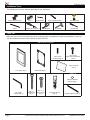
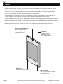
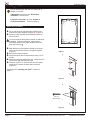
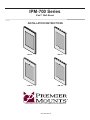
IPM-700 Series
iPad™ Wall Mount
INSTALLATION INSTRUCTIONS
IPM-700
IPM-710
IPM-720
IPM-730
CREATING POSITIVE CUSTOMER EXPERIENCES
9531-056-081-00
IPM-700 Series
Contents
Warning Statements.................................................................................................................................................. 2
Installation Tools........................................................................................................................................................ 3
Parts List................................................................................................................................................................... 3
Features.................................................................................................................................................................... 4
Installing to a Wall..................................................................................................................................................... 5
Installing the iPad™................................................................................................................................................ 13
Attaching the Cover................................................................................................................................................. 14
Technical Specifications.......................................................................................................................................... 14
Warranty.................................................................................................................................................................. 15
Warning Statements
PRIOR TO THE INSTALLATION OF THIS PRODUCT, THE INSTALLATION INSTRUCTIONS MUST BE READ AND
COMPLETELY UNDERSTOOD. KEEP THESE INSTALLATION INSTRUCTIONS IN AN EASILY ACCESSIBLE LOCATION
FOR FUTURE REFERENCE.
PROPER INSTALLATION PROCEDURE BY A QUALIFIED SERVICE TECHNICIAN MUST BE FOLLOWED, AS OUTLINED
IN THESE INSTALLATION INSTRUCTIONS. FAILURE TO DO SO COULD RESULT IN PROPERTY DAMAGE, SERIOUS
PERSONAL INJURY, OR EVEN DEATH.
SAFETY MEASURES MUST BE PRACTICED AT ALL TIMES DURING THE ASSEMBLY OF THIS PRODUCT. USE
PROPER SAFETY EQUIPMENT AND TOOLS FOR THE ASSEMBLY PROCEDURE TO PREVENT PERSONAL INJURY.
PREMIER MOUNTS DOES NOT WARRANT AGAINST DAMAGE CAUSED BY THE USE OF ANY PREMIER MOUNTS
PRODUCT FOR PURPOSES OTHER THAN THOSE FOR WHICH IT WAS DESIGNED OR DAMAGE CAUSED BY
UNAUTHORIZED ATTACHMENTS OR MODIFICATIONS, AND IS NOT RESPONSIBLE FOR ANY DAMAGES, CLAIMS,
DEMANDS, SUITS, ACTIONS OR CAUSES OF ACTION OF WHATEVER KIND RESULTING FROM, ARISING OUT OF OR
IN ANY MANNER RELATING TO ANY SUCH USE, ATTACHMENTS OR MODIFICATIONS.
Be aware of the mounting environment. If drilling and/or cutting into the mounting surface, always make sure that there
are no electrical wires in wall. Cutting or drilling into an electrical line may cause serious personal injury.
Make sure there are no water or natural gas lines inside the wall where the mount is to be located. Cutting or drilling into a
water or gas line may cause severe property damage or personal injury.
This product is intended for indoor use only. Use of this product outdoors could lead to product failure and/or serious
personal injury.
Do not install near sources of high heat. Do not install on a structure that is prone to vibration, movement or chance of
impact.
Contact Premier Mounts with any questions:
(800) 368-9700
[email protected]
Page 2
Visit the Premier Mounts website at http://www.premiermounts.com
Installation Instructions
IPM-700 Series
Installation Tools
The following tools may be required depending on your installation.
3/16" Drill Bit
Level
Electronic Stud Finder
3/16" Concrete Drill Bit
Hand Held Drill
2
1
Pencil
Phillips Tip Screwdriver
Tape Measure
Drywall Saw
Hammer
Parts List
Make sure none of the Premier Mounts parts are missing and/or damaged before beginning installation. If there are,
stop the installation and call Premier Mounts at (800) 368-9700.
IPM-700 Series Components
M3 x 12mm
Nylon Pan Head Screw
(Qty 2)
M3 x 12mm
Set Screw (Qty 2)
Paper Template
(Qty 1)
Front Plate (Qty 1)
Back Plate (Qty 1)
iPad2™ Kit
Adhesive-Backed
Bumper (Qty 4)
M1.5 Allen
Wrench (Qty 1)
Page 3
#10 x 2"
Wood Screw
(Qty 2)
#10 x 1¼"
Wood Screw
(Qty 4)
#10 Screw Anchor
(Qty 4)
Rubber Edge Trim (Qty 2)
Visit the Premier Mounts website at http://www.premiermounts.com
Installation Instructions
IPM-700 Series
Features
The IPM-700 Series of secure wall mounting frames is perfect for turning the iPad™ into a compact interactive
display for digital signage or control. This decorative and easy-to-install wall mount prevents unauthorized access
and does not obstruct reception to WiFi networks.
The IPM-700 covers all operation buttons, including the home button; the IPM-710 covers all operation buttons
except the home button; the IPM-720 covers all operation buttons and has a camera hole for the iPad2™; and the
IPM-730 has openings for the home button and camera hole for the iPad2™.
These mounting frames include screws and screw anchors for mounting on a single wood stud or in drywall or
concrete. Adhesive rubber strips and bumpers are also included for fitting iPad2’s™ into the frame.
To accommodate specific power and A/V cabling needs on drywall installations, the IPM-700 Series may be installed
over Premier Mounts’ optional In-Wall A/V and Power GearBox™ (GB-INWAVP). This GearBox™ includes knockouts
for power and signal access and can be easily installed in a wall. (The GB-INWAVP cannot be used with the IPM-700
Series in single-stud or concrete surface installations.)
Illustrations in this manual show the IPM-700 cover, but the instructions apply to any IPM-700 Series cover.
Perfect for Digital Signage
Different types of frame
covers for preventing
unauthorized access
Elegant Look
Available in chrome, stainless
steel, white and black finishes
Page 4
Ventilation
Openings at the top
and bottom of the
mount improve airflow
Easy Installation
Use only two screws for a wood
stud, or four screws for a drywall
or concrete surface
Visit the Premier Mounts website at http://www.premiermounts.com
Installation Instructions
IPM-700 Series
Installing to a Wall
Are you installing the IPM-700 to a wood stud, or
drywall or concrete?
If Wood Stud, continue to the “Wood Stud
Installation” section below.
THIS SIDE UP
X
If Drywall or Concrete, go to the “Drywall or Concrete Installation” section on page 6.
CUT THIS LINE IF USING GB-INWAVP
CUT THIS LINE IF USING GB-INWAVP
Wood Stud Installation
➊➊ Cut or punch out the top and bottom middle screw
CUT THIS LINE IF USING GB-INWAVP
➋➋
CL
holes on the paper template (marked “X”) (Figure 1).
Place the paper template at the desired location on
the wood stud.
You may install the back plate in portrait or landscape
orientation. If portrait orientation, make sure the
directional arrows on the paper template and back
plate are facing up .
CUT THIS LINE IF USING GB-INWAVP
X
CL
➌➌ Mark where the top and bottom middle screw holes
➎➎
➏➏
➐➐
➑➑
will be on the wall according to the paper template
(Figure 2).
Remove the paper template.
Drill pilot holes at the marked locations using a 3/16"
drill bit.
Place the back plate against the wall, making sure the
screw holes align with the pilot holes.
Insert two (2) #10 x 2” wood screws into the middle
screw holes to fasten the back plate to the wall
(Figure 2).
Figure 1
Continue to the “Installing the iPad™” section on
page 13.
Figure 2
#10 x 2"
Wood Screw
Figure 3
Page 5
Visit the Premier Mounts website at http://www.premiermounts.com
Installation Instructions
IPM-700 Series
Installing to a Wall (cont’d)
Drywall or Concrete Installation
THIS SIDE UP
Are you installing the IPM-700 with a GB-INWAVP
GearBox™ on a drywall surface?
X
X
CUT THIS LINE IF USING GB-INWAVP
If Yes, go to the “With GB-INWAVP” section on
page 7.
CUT THIS LINE IF USING GB-INWAVP
CL
CUT THIS LINE IF USING GB-INWAVP
If No, continue to the “Without GB-INWAVP”
section below.
CUT THIS LINE IF USING GB-INWAVP
X
Do not use the IPM-700 Series with GB-INWAVP on
concrete.
X
CL
Figure 1
Without GB-INWAVP
➊➊ Cut or punch out the corner screw holes on the paper
➋➋
template (marked “X”) (Figure 1).
Place the paper template at the desired location on
the drywall or concrete surface.
You may install the back plate in portrait or landscape
orientation. If portrait orientation, make sure the
directional arrows on the paper template and back
plate are facing up .
➌➌ Mark where the corner screw holes will be on the wall
➍➍
➎➎
according to the paper template (Figure 2).
Remove the paper template.
Drill pilot holes at the marked locations using a 3/16"
drill bit.
Figure 2
For concrete installation, use a 3/16" concrete drill
bit.
➏➏ Insert four (4) #10 screw anchors into the four holes
in the wall (Figure 3).
If necessary, use a hammer to lightly tap each screw
anchor into the wall.
➐➐ Place the back plate against the wall, making sure the
➑➑
#10 Screw Anchor
corner screw holes align with the screw anchors.
Insert four (4) #10 x 1¼” wood screws into the corner
screw holes to fasten the back plate to the wall
(Figure 4).
Figure 3
Continue to the “Installing the iPad™” section on
page 13.
#10 x 1¼"
Wood Screw
Figure 4
Page 6
Visit the Premier Mounts website at http://www.premiermounts.com
Installation Instructions
IPM-700 Series
Installing to a Wall (cont’d)
With GB-INWAVP
If you are using the IPM-700 Series with Premier
Mounts’ In-Wall A/V and Power GearBox™
(GB-INWAVP) (sold separately), install the GB-INWAVP
first.
Then install the IPM-700 Series mount over it for easy
cable and accessory management.
These instructions are for drywall installations only.
GB-INWAVP
(sold separately)
Step 1
➊➊ Use an electronic stud finder to locate all wall studs
➋➋
in the area in which you intend to install the IPM-700
Series mount and the GB-INWAVP.
Use a pencil and lightly mark the location of each
stud.
Page 7
Visit the Premier Mounts website at http://www.premiermounts.com
Installation Instructions
IPM-700 Series
Installing to a Wall (cont’d)
Step 2
➊➊ Cut a hole in the paper template where it says “CUT
➌➌
THIS SIDE UP
X
X
CUT THIS LINE IF USING GB-INWAVP
CUT THIS LINE IF USING GB-INWAVP
➋➋
THIS LINE”.
Cut or punch out the corner screw holes on the paper
template (marked “X”) (Figure 1).
Place the paper template at the desired location
between the studs (Figure 2).
You may install the back plate and GB-INWAVP in
portrait or landscape orientation. If portrait orientation,
make sure the directional arrows on the paper
template and back plate are facing up .
CL
CUT THIS LINE IF USING GB-INWAVP
➍➍ Trace the paper template’s large cutout on the wall.
➎➎ Mark where the corner screw holes will be on the wall
according to the paper template.
➏➏ Remove the paper template.
CUT THIS LINE IF USING GB-INWAVP
X
X
CL
Figure 1
Paper
Template
Figure 2
Page 8
Visit the Premier Mounts website at http://www.premiermounts.com
Installation Instructions
IPM-700 Series
Installing to a Wall (cont’d)
Step 3
Use a drywall saw to remove the drywall in the area you
marked in step 2 (Figure 3).
Avoid cutting electrical wires, water pipes, or gas
lines. Remove a small piece of drywall and use a
flashlight to look around for these hazards in the
area in which you will be cutting. Once you have
located any hazards, proceed to carefully remove
the rest of the drywall.
If you do locate any hazards, their presence may require
you to relocate either the hazard or the GB-INWAVP.
Consult a qualified professional prior to relocating
electrical lines, gas lines, or water pipes.
Step 4
If you will be routing the audio, video, and/or data
connections through the wall, remove the 1½˝ knockout.
The 1½˝ knockout is easily removed by pressing hard
with your thumbs on either side of the knockout, then
twisting the knockout until it comes free.
Watch for sharp edges.
1½˝ Knockouts for
Audio / Video / Data
Connections
Step 5
Insert the GB-INWAVP into the cutout.
Page 9
Visit the Premier Mounts website at http://www.premiermounts.com
Installation Instructions
IPM-700 Series
Installing to a Wall (cont’d)
Step 6
➊➊ Insert one (1) in-wall clamp through the T-notch and
➋➋
pull it forward.
Fasten with one (1) 6-32 x 2˝ pan head screw.
Do not overtighten the 6-32 x 2˝ pan head screw.
Note the proper orientation for the in-wall clamp.
➌➌ Repeat steps 1 and 2 for the remaining in-wall
clamp.
Continue to the “Outlet Box Installation” section on
page 11.
Proper Orientation
6-32 x 2˝ Pan head Screws
Drywall
In-Wall Clamps
Stud
Plan View
Proper Orientation
Improper Orientation
Page 10
Visit the Premier Mounts website at http://www.premiermounts.com
Installation Instructions
IPM-700 Series
Installing to a Wall (cont’d)
Outlet Box Installation
Installation of electrical power to your GB-INWAVP
should be performed by a qualified professional
electrician. Improper installation and handling of
live electrical wires can result in property damage
and severe personal injury.
The 110 volt duplex receptacle, flexible aluminum
conduit, and electrical wiring are not included with
your GB-INWAVP. You or your electrician can
purchase these at your local hardware store or
electrical supply shop.
The following steps presume that you have already
run flexible aluminum conduit and electrical wiring
up to your GB-INWAVP.
Not Included
Step 1
➊➊ Remove one of the ½˝ knockouts from the back of the
➋➋
➌➌
➍➍
Outlet Box.
Connect the flexible aluminum conduit using
commercially available conduit connectors most
appropriate for your specific installation.
Install a 110 volt duplex receptacle into the Outlet
Box.
Place the Outlet Box into your GB-INWAVP.
Step 2
Secure the Outlet Box to your GB-INWAVP using four
(4) 6-32 x ½" screws.
Do not overtighten the 6-32 x ½” screws.
Proceed to the “Installing the Cable Bushings”
section below.
Installing the Cable Bushings
The knockouts for your audio / video / data cables should
already be removed. If you have not removed them
yet, press hard with your fingertips on either side of the
knockouts, then twist the knockout until they come free.
Watch for sharp edges!
➊➊ Install the cable bushings gently pressing them into
the knockout holes.
➋➋ Run your audio, video, and data cables through the
cable bushings.
Continue to the “Installing the IPM-700 Series Over the
GB-INWAVP” section on page 12.
Page 11
Visit the Premier Mounts website at http://www.premiermounts.com
Installation Instructions
IPM-700 Series
Installing to a Wall (cont’d)
Installing the IPM-700 Series Over the GB-INWAVP
➊➊ Drill pilot holes at the marked locations using a 3/16"
drill bit.
➋➋ Insert four (4) #10 screw anchors into the four holes
in the wall (Figure 1).
If necessary, use a hammer to lightly tap each screw
anchor into the wall.
➌➌ Place the back plate against the wall, making sure the
corner screw holes align with the screw anchors.
If you are using portrait orientation, make sure the
directional arrow on the back plate is facing up .
➍➍ Insert four (4) #10 x 1¼” wood screws into the corner
screw holes to fasten the back plate to the wall
(Figure 2).
Continue to the “Installing the iPad™” section on
page 13.
#10 Screw Anchor
Figure 1
#10 x 1¼"
Wood Screw
Figure 2
Page 12
Visit the Premier Mounts website at http://www.premiermounts.com
Installation Instructions
IPM-700 Series
Installing the iPad™
If you are using an iPad2™, attach two (2) rubber
edge trims to the long tabs of the back plate as
shown (Figure 1).
Then attach four (4) adhesive-backed bumpers to
the notches on the back plate (Figure 2).
➊➊ Place the iPad™ on the back plate by easing it
➋➋
➌➌
against the top brackets, then the bottom brackets
(Figure 3).
Center the iPad™ on the back plate.
Insert two (2) M3 x 12mm nylon pan head screws
into the top brackets, then tighten them against the
iPad™ to secure it inside the back plate (Figure 4).
Rubber Edge Trim
Continue to the “Attaching the Cover” section on
page 14.
Figure 1
Adhesive-Backed
Bumper
Figure 2
➊➊
➋➋
M3 x 12mm
Nylon Pan Head Screw
Figure 3
Page 13
Visit the Premier Mounts website at http://www.premiermounts.com
Figure 4
Installation Instructions
IPM-700 Series
Attaching the Cover
➊➊ Use your fingers to pre-install two (2) M3 x 12mm set
screws to the bottom of the front plate (Figure 1).
➋➋ Hook the front plate over the top of the back plate,
➌➌
then ease it over the bottom of the back plate
(Figure 2).
Use the M1.5 Allen wrench to tighten the set screws.
➊➊
➋➋
Figure 1
M3 x 12mm
Set Screw
Figure 2
Technical Specifications
All measurements are in inches [millimeters].
7.94
202
6.16
156
5.00
127
5.91
150
7.85
199
12.12
308
10.00 6.84
254 174
5.65
144
.72
18
Page 14
Visit the Premier Mounts website at http://www.premiermounts.com
Installation Instructions
IPM-700 Series
IPM-700 Series
Warranty
PREMIER MOUNTS
LIMITED LIFETIME WARRANTY
What and Who is Covered by this Limited Warranty and for How Long
Premier Mounts warrants this product to be free from defects in material and workmanship for the lifetime of the original
owner of this product. The limited warranty is valid only for the original purchaser of the product.
What Premier Mounts Will Do
At the sole option of Premier Mounts, Premier Mounts will repair or replace any product or product part that is defective.
If Premier Mounts chooses to replace a defective product or part, a replacement product or part will be shipped to you
at no charge, but you must pay any labor costs.
What is Not Covered; Limitations
PREMIER MOUNTS DISCLAIMS ANY LIABILITY FOR DAMAGE TO MOUNTS, ADAPTERS, DISPLAYS,
PROJECTORS, OTHER PROPERTY, OR PERSONAL INJURY RESULTING, IN WHOLE OR IN PART, FROM
IMPROPER INSTALLATION, MODIFICATION, USE OR MISUSE OF ITS PRODUCTS.
PREMIER MOUNTS DISCLAIMS ALL OTHER WARRANTIES, EXPRESS OR IMPLIED, INCLUDING WARRANTIES
OF MERCHANTABILITY AND FITNESS FOR A PARTICULAR PURPOSE. PREMIER MOUNTS IS NOT
RESPONSIBLE FOR INCIDENTAL OR CONSEQUENTIAL DAMAGES, INCLUDING BUT NOT LIMITED TO,
INABILITY TO USE ITS PRODUCTS OR LABOR COSTS FOR REMOVING AND REPLACING DEFECTIVE
PRODUCTS OR PARTS. SOME STATES DO NOT ALLOW THE EXCLUSION OR LIMITATION OF INCIDENTAL OR
CONSEQUENTIAL DAMAGES, SO THE ABOVE LIMITATION OR EXCLUSION MAY NOT APPLY TO YOU.
What Customers Must Do for Limited Warranty Service
If you discover a problem that you think may be covered by the warranty you MUST REPORT it in writing to the address
below within thirty (30) days. Proof of purchase (an original sales receipt) from the original consumer purchaser must
accompany all warranty claims. Warranty claims must also include a description of the problem, the purchaser’s name,
address, and telephone number. General inquiries can be addressed to Premier Mounts Customer Service at 1-800368-9700. Warranty claims will not be accepted over the phone or by fax.
Premier Mounts
Attn: Warranty Claim
3130 East Miraloma Ave.
Anaheim, CA 92806
How State Law Applies
THIS WARRANTY GIVES YOU SPECIFIC LEGAL RIGHTS, AND YOU MAY ALSO HAVE OTHER RIGHTS WHICH
VARY FROM STATE TO STATE.
Disclaimer
Premier Mounts intends to make this manual accurate and complete. However, Premier Mounts makes no claim that
the information contained herein covers all details, conditions or variations, nor does it provide for every possible
contingency in connection with the installation or use of this product. The information contained in this document
is subject to change without notice or obligation of any kind. Premier Mounts makes no representation of warranty,
expressed or implied, regarding the information contained herein. Premier Mounts assumes no responsibility for
accuracy, completeness or sufficiency of the information contained in this document.
Contact Us
NORTH AMERICA
3130 East Miraloma Avenue
Anaheim, CA 92806 USA
USA and Canada
Phone: 1-800-368-9700
Fax: 1-800-832-4888
Other Locations
Phone: (001) 714-632-7100
Fax: (001) 714-632-1044
EUROPE
Unit 3, The Moorings Business Park,
Channel Way, Longford,
Coventry, CV6 6RH, UK
Phone: +44 (0) 24 7664 4105
Fax: +44 (0) 24 7664 4165
©Premier Mounts 2011
Installation Instructions
Visit the Premier Mounts website at http://www.premiermounts.com
Page 15