1
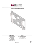
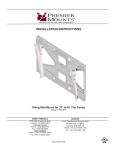
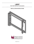
CREATING POSITIVE CUSTOMER EXPERIENCES
INSTALLATION INSTRUCTIONS
Extending Swivel Mount for Flat-Panels
Model: AM225
NORTH AMERICA
3130 East Miraloma Avenue
Anaheim, CA 92806 USA
USA and Canada
Phone: 1-800-368-9700
Fax: 1-800-832-4888
Other Locations
Phone: (001)-714-632-7100
Fax: (001)-714-632-1044
EUROPE
Unit 3, The Moorings Business Park,
Channel Way, Longford,
Coventry, CV6 6RH, UK
Phone: +44 (0) 24 7664 4105
Fax: +44 (0) 24 7664 4165
9531-021-001-02
AM225
Contents
Weight Limit............................................................................................................................................................... 2
Warning Statements.................................................................................................................................................. 2
Installation Tools........................................................................................................................................................ 3
Parts List................................................................................................................................................................... 3
Features.................................................................................................................................................................... 4
Building the Wall Frame............................................................................................................................................ 5
Installing the Wall Frame........................................................................................................................................... 6
Introduction................................................................................................................................................... 6
Determining the Mounting Surface............................................................................................................... 6
Wood Stud Installation.................................................................................................................................. 6
Concrete Installation..................................................................................................................................... 8
Installing the Pullout Mount..................................................................................................................................... 10
Attach a P-Series Mount and/or Accessories.......................................................................................................... 11
Post-Installation Adjustments.................................................................................................................................. 11
Cable Routing.......................................................................................................................................................... 12
Technical Specifications.......................................................................................................................................... 12
Warranty.................................................................................................................................................................. 13
Weight Limit
Maximum Flat Panel Weight:
225 lbs.
THE WALL STRUCTURE MUST BE CAPABLE OF
SUPPORTING AT LEAST FIVE TIMES THE WEIGHT OF
THE FLAT PANEL. IF NOT, THE WALL STRUCTURE MUST
BE REINFORCED.
Warning Statements
PRIOR TO THE INSTALLATION OF THIS PRODUCT, THE INSTALLATION INSTRUCTIONS MUST BE READ AND
COMPLETELY UNDERSTOOD. KEEP THESE INSTALLATION INSTRUCTIONS IN AN EASILY ACCESSIBLE LOCATION
FOR FUTURE REFERENCE.
PROPER INSTALLATION PROCEDURE BY A QUALIFIED SERVICE TECHNICIAN MUST BE FOLLOWED, AS OUTLINED
IN THESE INSTALLATION INSTRUCTIONS. FAILURE TO DO SO COULD RESULT IN PROPERTY DAMAGE, SERIOUS
PERSONAL INJURY, OR EVEN DEATH.
SAFETY MEASURES MUST BE PRACTICED AT ALL TIMES DURING THE ASSEMBLY OF THIS PRODUCT. USE
PROPER SAFETY EQUIPMENT AND TOOLS FOR THE ASSEMBLY PROCEDURE TO PREVENT PERSONAL INJURY.
PREMIER MOUNTS DOES NOT WARRANT AGAINST DAMAGE CAUSED BY THE USE OF ANY PREMIER MOUNTS
PRODUCT FOR PURPOSES OTHER THAN THOSE FOR WHICH IT WAS DESIGNED OR DAMAGE CAUSED BY
UNAUTHORIZED ATTACHMENTS OR MODIFICATIONS, AND IS NOT RESPONSIBLE FOR ANY DAMAGES, CLAIMS,
DEMANDS, SUITS, ACTIONS OR CAUSES OF ACTION OF WHATEVER KIND RESULTING FROM, ARISING OUT OF OR
IN ANY MANNER RELATING TO ANY SUCH USE, ATTACHMENTS OR MODIFICATIONS.
At least two qualified people should perform the assembly procedure. Personal injury and/or property damage can result
from dropping or mishandling the flat panel.
If mounting to wall studs, make sure that the mounting screws are anchored into the center of the wall studs. Use of an
edge-to-edge stud finder is recommended.
Be aware of the mounting environment. If drilling and/or cutting into the mounting surface, always make sure that there
are no electrical wires in wall. Cutting or drilling into an electrical line may cause serious personal injury.
Make sure there are no water or natural gas lines inside the wall where the mount is to be located. Cutting or drilling into a
water or gas line may cause severe property damage or personal injury.
This product is intended for indoor use only. Use of this product outdoors could lead to product failure and/or serious
personal injury.
Do not install near sources of high heat. Do not install on a structure that is prone to vibration, movement or chance of
impact.
Contact Premier Mounts with any questions:
(800) 368-9700
[email protected]
Page 2
Visit the Premier Mounts website at http://www.premiermounts.com
Installation Instructions
AM225
Installation Tools
The following tools may be required, dependent upon your particular installation. These tools are not provided by
Premier Mounts, but you can purchase them at your local hardware store.
¼˝ Drill Bit for
Wood Stud
Electronic Stud Finder
/16˝ Concrete Drill Bit**
Hand Held Drill
Hammer**
Level
5
2
1
Pencil
Tape Measure
Zip Ties
Socket Wrench
M10 Socket*
½˝ Socket
Phillips Tip Screwdriver
** Optional tools for concrete installations.
Parts List
Your Premier Mounts product is shipped with all proper installation hardware and components. Make sure that none
of these parts are missing and/or damaged before beginning installation. If there are parts missing and/or damaged,
please stop the installation and contact Premier Mounts at (800) 368-9700.
AM225 Mount Components
Pullout Mount
(Qty 1)
M4 x 8mm Combo
Phillips Screw (Qty 8)
5
16
˝ x 3” Hex Lag Bolts
(Qty 4)
Installation Instructions
M5 x 8mm Combo
Phillips Screw (Qty 2)
Wall Mounting Bracket
(Qty 2)
M8 x 12mm Combo
Phillips Screw (Qty 4)
Crosspiece Bracket
(Qty 2)
M8 x 16mm Combo
Phillips Screw (Qty 4)
5
16
˝ Flat Washer - Metal
(Qty 4)
M2.5 Allen Wrench
(Qty 1)
Visit the Premier Mounts website at http://www.premiermounts.com
Page 3
AM225
Features
The Extending Swivel Mount (AM225) is the ideal wall mount for flat-panels. It extends smoothly up to 20 inches from
the wall, and allows simple post-installation leveling and swivel adjustments for the perfect viewing angle. Its open
design makes it easy to set up cable and electrical wiring. The AM225 works with the P-Series P4263F or P4263T flatpanel mount to help support the display.
Stylish Design
Sleek, sturdy and unobtrusive.
Adjustable Extension
Your flat panel stays at
the extension you choose
regardless of flat-panel
size or weight.
Post-Installation
Adjustments
Remove the M5 side
screws on top of the
mounting plate to allow for
swivel.
Robust Mount Design
The heavy duty wall frame
ensures that your flat-panel
stays were you installed it.
Versatile
Use a P4263F or P4263T
mount to attach the display
to the AM225.
Page 4
Cable Management
Use zip ties and openings to keep
cables from being pinched and
reduce unsightly cable clutter.
Installation on Stud Placement
The mounting brackets are
designed to easily attach to 12” or
16” studs.
Visit the Premier Mounts website at http://www.premiermounts.com
Installation Instructions
AM225
Building the Wall Frame
Use eight (8) M4 x 8mm combo Phillips screws to attach the two (2) crosspiece brackets to the two (2) wall
mounting brackets (Fig. 1).
Make sure the brackets are facing in the same direction as shown (Fig. 1).
The screws must been inserted as shown (Fig. 2 and Fig. 3)
M4 x 8mm combo Phillips
screw
M4 x 8mm combo Phillips
screw
Fig. 1
Fig. 2
Top of Wall Frame
Fig. 3
Bottom of Wall Frame
Proceed to the “Installing the Wall Frame” section.
Installation Instructions
Visit the Premier Mounts website at http://www.premiermounts.com
Page 5
AM225
Installing the Wall Frame
Introduction
Facing the Front
Make sure the flat side of the wall frame’s
crosspiece brackets is facing the front.
Mounting Safety
Two people are recommended for installing this
mount.
Front-facing wall frame
Determining the Mounting Surface
If you will be installing your AM225 mount to wood
studs, proceed to the “Wood Stud Installation”
section.
If you will be installing your AM225 mount to a concrete
wall, proceed to the “Concrete Installation” section.
Wo
od
Co
ncr
ete
Stu
d
Wood Stud Installation
Step 1
X
You must secure the wall frame to two (2) wall
studs with a minimum of four (4) lag bolts (2 lag
bolts for each stud found).
X
Use a stud finder to determine the exact center of
wall studs in the vicinity of the wall frame.
Use a pencil to mark the exact center of each of the
wall studs.
Step 2
Two people are recommended for this step; one
person to level the wall frame and another person
to mark the wall stud location.
Place the wall frame against the wall in the desired
viewing location.
Adjust the wall frame to align the mount slots in the
wall frame with the center of the wall studs.
Level the wall frame.
Use a pencil to mark the upper right mounting
location along the center of the wall stud.
Page 6
Visit the Premier Mounts website at http://www.premiermounts.com
Installation Instructions
AM225
Installing the Wall Frame (cont’d)
Step 3
Drill a “pilot hole” in the center of the upper right mark
using a ¼˝ drill bit and power drill.
Only use a ¼˝ drill bit when drilling the pilot holes.
Step 4
Place the wall frame against the wall and align it
with the pilot hole.
Insert one (1) 5/16˝ x 3˝ lag bolt and one (1) 5/16˝
washer into the upper right mounting hole and
tighten using a socket wrench and ½˝ socket.
Do not overtighten the lag bolt.
Step 5
Level the wall frame.
Use a pencil to mark the remaining three (3)
mounting locations along the center of each wall
stud.
Step 6
Two people are recommended for this step; one
person to level the wall frame and another person
to drill the pilot holes.
Drill a “pilot hole” in the center of each of the marks with
a power drill and a ¼˝ drill bit.
Only use ¼˝ drill bit when drilling the pilot holes.
Installation Instructions
Visit the Premier Mounts website at http://www.premiermounts.com
Page 7
AM225
Installing the Wall Frame (cont’d)
Step 7
Insert one (1) 5/16˝ x 3˝ lag bolt and one (1) 5/16˝ washer
into each pilot hole.
The wide mounting slots in the wall frame allow lateral
shift to help you precisely position the pullout mount.
Tighten all lag bolts using a socket wrench and ½˝
socket.
Do not overtighten the lag bolts when attaching the
mount to the wall. Improper installation may result in
personal injury or property damage.
Proceed to the “Installing the Mounting Bracket” section.
Concrete Installation
The supplied 5/16˝ concrete wedge anchors must be
used for concrete installation.
You will need a 5/16˝ concrete drill bit, which is
available at your closest hardware store.
Concrete Wedge Anchors (not included)
Example of 5/16˝ Concrete Drill Bit (not Included)
Step 1
Two people are recommended for this step; one
person to level the wall frame and another person
to mark the mounting locations.
>1
2”
Place the wall frame against the wall in the desired
viewing location.
Level the wall frame.
Use a pencil and mark 2 upper and 2 lower
mounting locations where you will be drilling holes
for the concrete wedge anchors. Each horizontal
location cannot be closer than 12˝ apart.
Set the wall frame to one side in a safe location.
Step 2
Use a power drill and 5/16˝ concrete drill bit to drill a hole
at each of the marks.
Page 8
Visit the Premier Mounts website at http://www.premiermounts.com
Installation Instructions
AM225
Installing the Wall Frame (cont’d)
Step 3
Insert a concrete wedge anchor into each hole.
If necessary, lightly tap each concrete wedge anchor
into place with a hammer.
Remove the nuts and washers from all four (4)
concrete wedge anchors.
Step 4
Place the wall frame against the wall over the
threaded shafts of the concrete wedge anchors.
Replace the washers which you removed from
the concrete wedge anchors with the 5/16˝ washers
shown in the parts list on Page 3.
Attach the nuts and 5/16˝ washers to each of the
concrete wedge anchors and tighten using a socket
wrench and an M10 socket.
The wide mounting slots in the wall frame allow
lateral shift to help you precisely position the
pullout mount.
Do not overtighten the wedge anchor nuts.
Installation Instructions
Visit the Premier Mounts website at http://www.premiermounts.com
Page 9
AM225
Installing the Pullout Mount
➊➊ Pre-install two (2) M8 x 12mm combo Phillips
M8 x 12mm combo Phillips
screw
screws in the top screw holes of the wall frame
(Fig.1) using at least 5 full turns.
Leave a gap between the heads of the screws and
the wall frame for hanging the pullout mount.
➋➋ Hang the pullout mount on the M8 x 12mm combo
screws that were pre-installed in the wall frame
(Fig. 2).
The keyhole design
of the pullout mount’s
screw holes makes hanging easier.
➌➌
Wall Frame
Fig. 1
Use (2) M8 x 12mm combo Phillips screws to attach
the bottom of the pullout mount to the wall frame
(Fig. 3).
➍➍ Use two (2) M5 x 8mm combo Phillips screws to
attach the middle of the pullout mount to the wall
frame (Fig. 3).
➎➎ Tighten the top M8 x 12mm combo Phillips screws.
Proceed to the “Attach a P-Series Mount and/or
Accessories” section.
Pullout Mount
Fig. 2
M5 x 8mm combo Phillips
screw
M8 x 12mm combo Phillips
screw
Fig. 3
Page 10
Visit the Premier Mounts website at http://www.premiermounts.com
Installation Instructions
AM225
Attach a P-Series Mount and/or Accessories
Use four (4) M8 x 16mm pan Phillips screws to attach
the P-Series P4263F or P4263T flat-panel mount to the
AM225.
Follow the installation instructions included with the
P-Series mount.
Make sure the P-Series mount is aligned to the
center of the pullout portion of the AM225.
Proceed to the “Post-Installation Adjustments”
section.
AM225 with P4263T tilt
mount
AM225 with P4263F flat
mount
Post-Installation Adjustments
➊➊ Remove the M5 top-side screws on location “A” to
A
swivel.
You cannot re-insert the top-side screws unless the
mounting plate is centered.
Do not remove the M8 middle screw.
➋➋ Use an M2.5 Allen wrench to loosen the screws on
locations “B” to adjust the pullout tension.
Stop loosening when the desired tension is
achieved.
Proceed to the “Cable Routing” section.
B
Back view of the AM225
pullout mount
Installation Instructions
Visit the Premier Mounts website at http://www.premiermounts.com
Page 11
AM225
Cable Routing
Neatly organize cabling and wiring by:
•Routing them through the openings in the pullout
Cable Routing Openings
mount.
•Using zip ties (not included) through the zip-tie
holders on the side brackets.
Zip-tie Holders
Technical Specifications
All measurements are in inches [mm].
421
16.6
247.65
9.75
477.67
18.806
92
3.60
156.46
6.16 0
198.63
7.820
420.4
16.5
114.3 0
4. 5
Page 12
Visit the Premier Mounts website at http://www.premiermounts.com
Installation Instructions
AM225
Warranty
PREMIER MOUNTS
LIMITED LIFETIME WARRANTY
What and Who is Covered by this Limited Warranty and for How Long
Premier Mounts warrants this product to be free from defects in material and workmanship for the lifetime of the original
owner of this product. The limited warranty is valid only for the original purchaser of the product.
What Premier Mounts Will Do
At the sole option of Premier Mounts, Premier Mounts will repair or replace any product or product part that is defective.
If Premier Mounts chooses to replace a defective product or part, a replacement product or part will be shipped to you
at no charge, but you must pay any labor costs.
What is Not Covered; Limitations
PREMIER MOUNTS DISCLAIMS ANY LIABILITY FOR DAMAGE TO MOUNTS, ADAPTERS, DISPLAYS,
PROJECTORS, OTHER PROPERTY, OR PERSONAL INJURY RESULTING, IN WHOLE OR IN PART, FROM
IMPROPER INSTALLATION, MODIFICATION, USE OR MISUSE OF ITS PRODUCTS.
PREMIER MOUNTS DISCLAIMS ALL OTHER WARRANTIES, EXPRESS OR IMPLIED, INCLUDING WARRANTIES
OF MERCHANTABILITY AND FITNESS FOR A PARTICULAR PURPOSE. PREMIER MOUNTS IS NOT
RESPONSIBLE FOR INCIDENTAL OR CONSEQUENTIAL DAMAGES, INCLUDING BUT NOT LIMITED TO,
INABILITY TO USE ITS PRODUCTS OR LABOR COSTS FOR REMOVING AND REPLACING DEFECTIVE
PRODUCTS OR PARTS. SOME STATES DO NOT ALLOW THE EXCLUSION OR LIMITATION OF INCIDENTAL OR
CONSEQUENTIAL DAMAGES, SO THE ABOVE LIMITATION OR EXCLUSION MAY NOT APPLY TO YOU.
What Customers Must Do for Limited Warranty Service
If you discover a problem that you think may be covered by the warranty you MUST REPORT it in writing to the address
below within thirty (30) days. Proof of purchase (an original sales receipt) from the original consumer purchaser must
accompany all warranty claims. Warranty claims must also include a description of the problem, the purchaser’s name,
address, and telephone number. General inquiries can be addressed to Premier Mounts Customer Service at 1-800368-9700. Warranty claims will not be accepted over the phone or by fax.
Premier Mounts
Attn: Warranty Claim
3130 East Miraloma Ave.
Anaheim, CA 92806
How State Law Applies
THIS WARRANTY GIVES YOU SPECIFIC LEGAL RIGHTS, AND YOU MAY ALSO HAVE OTHER RIGHTS WHICH
VARY FROM STATE TO STATE.
Disclaimer
Premier Mounts intends to make this manual accurate and complete. However, Premier Mounts makes no claim that
the information contained herein covers all details, conditions or variations, nor does it provide for every possible
contingency in connection with the installation or use of this product. The information contained in this document
is subject to change without notice or obligation of any kind. Premier Mounts makes no representation of warranty,
expressed or implied, regarding the information contained herein. Premier Mounts assumes no responsibility for
accuracy, completeness or sufficiency of the information contained in this document.
©Premier Mounts 2011
Installation Instructions
Visit the Premier Mounts website at http://www.premiermounts.com
Page 13