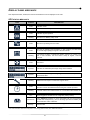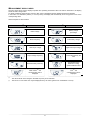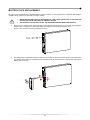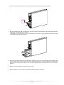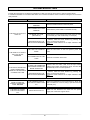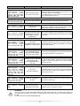
1
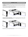
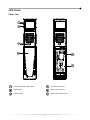
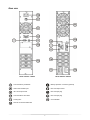
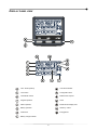
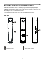
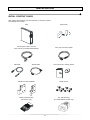
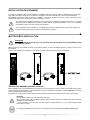
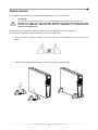
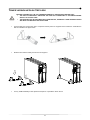
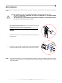
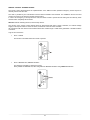
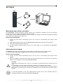
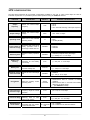
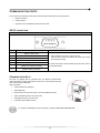
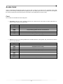
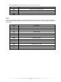
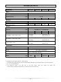
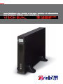
INTRODUCTION Congratulations on purchasing a UPS Vision Dual product and welcome to Riello UPS! To use the support service offered by Riello UPS, visit the site www.riello-ups.com Our Company is a specialist in the design, development and manufacturing of uninterruptible power supplies (UPS). The UPS described in this manual is a high quality product which has been carefully designed and built in order to guarantee the highest levels of performance. This device can be installed by anyone on the condition that they have READ THIS INSTALLTION AND USER MANUAL CAREFULLY. The UPS and the Battery Box generate DANGEROUS internal electrical voltages. All maintenance operations must be carried out by suitably qualified operators. This manual contains detailed instructions for using and installing the UPS and any additional Battery boxes. For information on how to use and maximise the performance of your device, please retain the CD containing this manual and read it carefully before operating the equipment. ENVIRONMENTAL PROTECTION In the development of its products, the company devotes abundant resources to analysing the environmental aspects. All our products pursue the objectives defined in the environmental management system developed by the company in compliance with applicable standards. No hazardous materials such as CFCs, HCFCs or asbestos are used in this product. When evaluating packaging, the choice of material has been made favouring recyclable materials. For correct disposal, please separate and identify the type of material of which the packaging is made according to the table below. Dispose of all material in compliance with applicable standards in the country in which the product is used. DESCRIPTION MATERIAL Box Cardboard Packaging corner Stratocell Protective bag Polythene Accessories bag Polythene DISPOSING OF THE PRODUCT The UPS and the Battery Box contain electronic PCBs and batteries which are considered TOXIC and HAZARDOUS waste. When the product reaches the end of its operating life, dispose of it in accordance with applicable local legislation. Disposing of the product correctly contributes to respecting the environment and personal health. © The reproduction of any part of this manual, in whole or in part, is forbidden without the prior consent of the manufacturer. In order to make improvements, the manufacturer reserves the right to modify the product described at any moment and without notice. 2 CONTENTS PRESENTATION 5 UPS VIEWS 6 FRONT VIEW 6 REAR VIEW 7 DISPLAY PANEL VIEW 8 BATTERY BOX (ACCESSORY NOT SUPPLIED WITH THE UPS) 9 9 REAR VIEW INSTALLATION 10 INITIAL CONTENT CHECK 10 INSTALLATION ENVIRONMENT 11 BATTERY BOX INSTALLATION 11 11 SETTING THE NOMINAL BATTERY CAPACITY TOWER VERSION 12 TOWER VERSION WITH BATTERY BOX 13 RACK VERSION 14 USE 15 CONNECTIONS AND SWITCHING ON FOR THE FIRST TIME 15 SWITCHING ON FROM THE MAINS 15 SWITCHING ON FROM THE BATTERY 15 SWITCHING OFF THE UPS 15 DISPLAY PANEL MESSAGES 16 UPS STATUS MESSAGES 16 MEASUREMENT DISPLAY AREA 17 CONFIGURING THE OPERATING MODE 18 POSSIBLE SETTINGS 18 ADDITIONAL FUNCTIONS 18 SOFTWARE 20 MONITORING AND CONTROL SOFTWARE 20 CONFIGURATION SOFTWARE 20 UPS CONFIGURATION 21 COMMUNICATION PORTS 22 RS232 CONNECTOR 22 COMMUNICATION SLOT 22 3 BATTERY PACK REPLACEMENT 23 TROUBLESHOOTING 25 ALARM CODES 27 FAULT 27 LOCK 28 TECHNICAL DATA 29 4 PRESENTATION The VISION DUAL series is the ideal solution for high end users who require high security and versatility from their power systems. The VISION DUAL is the best protection system available for network devices, servers and conventional storage systems. The VISION DUAL series is a range of UPS which utilises the very latest Line Interactive technology and sinusoidal output voltage waveforms. This technology allows high efficiency and reduced energy consumption, whilst guaranteeing a high level of protection against disturbances from the mains supply. This family was designed with versatility in mind, allowing for installation in both tower and rack positions. The following shows how the product can be installed in the two different positions: The UPS is also equipped with a dedicated battery pack that allows for easy battery replacement (hot swap) in complete safety thanks to the protected connection system. It is possible to use one or more autonomy expansion units known as BATTERY BOXES (optional accessories) with the same dimensions and aesthetic appearance as the UPS. ER series models are fitted with upgraded battery charges for long runtime and business continuity applications. For these versions, the batteries are housed in separate cabinets. 5 UPS VIEWS FRONT VIEW Extractable/rotatable display plate Removable front panel Release slits Battery pack connector ON/OFF Switch Battery pack retention panel 6 REAR VIEW Model 1100VA / 1500VA Model 2200VA / 3000VA Communication port RS232 Battery expansion connector (optional) USB communication port IEC 10A output socket IEC 16A output socket IEC 16A input plug Communication Card Slots IEC 10A input plug Cooling fans Circuit breaker Remote control terminal board 7 DISPLAY PANEL VIEW “SEL” button (Select) Load level indicator “ON” button Configuration area “STAND-BY” button Maintenance request Regular operation Timer Mains operation Measurement display area Battery operation Stand-by / alarm AVR active EnergyShare Battery charge indicator 8 BATTERY BOX (ACCESSORY NOT SUPPLIED WITH THE UPS) The BATTERY BOX is an optional accessory for this range of UPS (same dimensions and aesthetic appearance). The BATTERY BOX contains batteries which allow the operating time of the uninterruptible power supplies to be increased during extended blackouts. The number of batteries contained can vary according to the type of UPS for which the BATTERY BOX is intended. It is therefore necessary to take great care to ensure that the battery voltage of the BATTERY BOX is the same as the voltage permitted by the UPS. Several battery boxes can be connected in series to achieve a longer extended runtime. If the UPS is connected to a battery box, the maximum active power is derated from PF 0,9 to PF 0,8. REAR VIEW Front view Front view (without panel) Rear view Extractable/ rotatable battery box plate Battery isolator Removable front panel Battery expansion connector 9 INSTALLATION INITIAL CONTENT CHECK After opening the packaging, it is first necessary to check the contents. The package must contain: UPS Support feet Schuko power cable - IEC 10A (IEC 16A only for models 2200/3000VA) 2 IEC 10A connection cables USB cable RS232 cable User manual CD + Safety manual Handles for rack installation Handle screws Battery expansion plug (ER version only) IEC 16A male plug (For 2200/3000VA models only) 10 INSTALLATION ENVIRONMENT The UPS and the Battery Box must be installed in ventilated, clean environments which are sheltered from bad weather. The relative humidity in the environment must not exceed the maximum values shown in the Technical Data table. The ambient temperature, whilst the UPS is in operation, must remain between 0 and 40°C, and the UPS must not be positioned in places which are exposed to direct sunlight or to hot air. The recommended operating temperature for the UPS and the batteries is between 20 and 25°C. The actual operating life of the batteries is 5 years on average with an operating temperature of 20°C. If the operating temperature reaches 30°C, the operating life is halved. This is a category C2 UPS product. In a residential environment, this product may cause radio interference, in which case the user may be required to take additional measures. BATTERY BOX INSTALLATION ATTENTION: CHECK ON THE DATA PLATE THAT THE VOLTAGE OF THE BATTERY BOX IS THE SAME AS THAT ALLOWED BY THE UPS. Battery boxes can be installed in series for extended runtimes. Connect the Battery Boxes in series as shown in the figure below: If the UPS is connected to a battery box, the maximum active power is derated from PF 0,9 to PF 0,8. SETTING THE NOMINAL BATTERY CAPACITY Before installing one or more Battery Boxes, the UPS must be configured in order to update the nominal capacity value (total Ah UPS's internal batteries + external batteries) using the dedicated configuration software UPSTools contained on the CD-ROM supplied with the UPS. The battery box must only be installed while the UPS is switched off and disconnected from the mains power supply. CAUTION: The connection cables cannot be extended by the user. After connecting the UPS to its Battery Boxes, insert the fuses and turn the Battery Box battery isolators (SWBATT) to the ON position. It is not possible to connect more than one UPS to a single battery box, or to several Battery Boxes connected in a series. To check the availability of a new version of the latest software, visit the website www.riello-ups.com. 11 TOWER VERSION This chapter describes the steps for preparing the UPS and battery box for tower version use. ATTENTION: For your safety and that of the product, you must carefully follow the instructions given here below. BEFORE YOU CARRY OUT THE FOLLOWING SEQUENCE OF OPERATIONS, MAKE SURE THAT THE UPS IS COMPLETELY SWITCHED OFF AND NOT CONNECTED TO THE MAINS POWER SUPPLY OR TO ANY LOAD Once removed from the packaging, the UPS is already preset for installation in the tower configuration. To complete the configuration, simply mount the UPS on the two support feet. Each leg consists of two parts, connecting to each other at joints. To put a leg together proceed as shown in the figure. Assemble two legs and secure the UPS on top of them as shown in the figure below. 12 TOWER VERSION WITH BATTERY BOX BEFORE CARRING OUT THE FOLLOWING SEQUENCE OF OPERATIONS, ENSURE THAT: • THE UPS IS COMPLETELY SWITCHED OFF AND NOT CONNECTED TO THE MAINS POWER SUPPLY OR TO ANY LOAD. • THE BATTERY BOX IS DISCONNECTED FROM THE UPS, FROM ANY OTHER BATTERY BOXES AND WITH THE BATTERY ISOLATOR OPEN For the battery box version each foot is composed of three parts: two supports and an extension. Assemble two feet as indicated in the figure below. Slide the UPS and the battery box into the two supports For any additional battery boxes repeat the sequence of operations shown above. 13 RACK VERSION The sequence of operations to be followed in order to transform the UPS or battery box into rack version are described below. BEFORE CARRING OUT THE FOLLOWING SEQUENCE OF OPERATIONS, ENSURE THAT: • THE UPS IS COMPLETELY SWITCHED OFF AND NOT CONNECTED TO THE MAINS POWER SUPPLY OR TO ANY LOAD. • THE BATTERY BOX IS DISCONNECTED FROM THE UPS, FROM ANY OTHER BATTERY BOXES AND WITH THE BATTERY ISOLATOR OPEN 1- Pick up the panel from the sides and gently pull it away from its position just enough to be able to rotate it. ATTENTION: The panel must be removed carefully DO NOT ATTEMPT IN ANY WAY TO REMOVE THE PANEL FROM THE UPS 2- Rotate the panel 90° counter clockwise and reinsert it carefully into the special housing. 3 - At this point, with the UPS or battery box in the horizontal position, secure the handles using the screws provided, as shown in the figure. NOTE: Given the heavy weight, the use of support brackets is mandatory during rack installation (guide with L-shaped support). For the same reason, it is recommended that the UPS and battery box be installed in the lower part of the rack cabinet. 14 USE CONNECTIONS AND SWITCHING ON FOR THE FIRST TIME 1) Check that there is a protection device against overcurrents and short circuits in the system upstream from the UPS. The recommended protection value is 10A (for the 1100VA and 1500VA versions) and 16A (for the 2200VA, 3000VA and ER versions) with a B or C trip curve. 2) Power the UPS using the input cable provided. 3) Press the ON/OFF switch located on the front panel. 4) After a few moments, the UPS will switch on, the display will light up, there will be a beep and the icon will start to flash. The UPS is in stand-by mode: meaning that it is only consuming a small amount of power. The microcontroller supervising the self-diagnoses is powered; the batteries are charging; and everything is ready for UPS activation. Battery operation is also in stand-by mode provided that the timer is active. 5) Connect the equipment to be powered into the sockets on the back of the UPS, using the cable supplied or a cable no longer than 10 metres. CAUTION: do not connect equipment which absorbs more than 10A to the IEC 10A sockets. For equipment which exceeds this level of absorption, use the IEC 16A socket only (available on the 2200/3000VA version). 6) Check which operating mode is set on the display and, if necessary, see the “Configuring operating modes” paragraph to set the required mode. For advanced UPS configurations execute the software UPSTools which can be downloaded from the web site www.riello-ups.com. SWITCHING ON FROM THE MAINS 1) Press the “ON” button for 1 second. After pressing it, all the icons on the display light up for 1 second and the UPS beeps. 2) Switch on the equipment connected to the UPS. When switching on for the first time only: after 30 seconds, check that the UPS is operating correctly: 1) Simulate a blackout by disconnecting power to the UPS. 2) The load must continue to be powered, the every 4 seconds. icon on the display must light up and there must be a beep 3) When power is reconnected, the UPS must go back to operating from the mains. SWITCHING ON FROM THE BATTERY 1) Press the ON/OFF switch located on the front panel. 2) Hold down the “ON” button for at least 5 seconds. All the icons on the display light up for 1 second. 3) Switch on the equipment connected to the UPS. SWITCHING OFF THE UPS In order to switch off the UPS, hold down the “STBY” button for at least 2 seconds. The UPS goes back to stand-by mode and the icon starts to flash: 1) If the mains power is present, the ON/OFF switch must be pressed to completely turn off the UPS. 2) During battery mode operation with the timer not set, the UPS automatically switches off after 30 seconds. However if, the timer is set, press and hold down the "STBY" key for at least 5 seconds to turn off the UPS. For complete shutdown, press the ON/OFF switch. 15 DISPLAY PANEL MESSAGES This chapter describes, in detail, the various information that can be displayed on the LCD. UPS STATUS MESSAGES ICON STATUS Fixed Flashing Fixed Flashing DESCRIPTION Indicates a fault The UPS is in stand-by mode Indicates regular operation The UPS is in “Battery swap” mode Fixed The UPS is operating from the mains Fixed The UPS is operating from the battery. In this condition, the UPS emits an acoustic signal (beep) at regular 4-second intervals. Flashing Low battery pre-alarm. Indicates that battery autonomy is coming to an end. In this condition, the UPS emits a beep at regular 1-second intervals. Fixed AVR active Dynamic Indicates the estimated percentage charge of the batteries Dynamic Indicates the percentage of charge applied to the UPS compared with the nominal value. Flashing Maintenance is required. Contact the support centre. Fixed Indicates that the timer is active (programmed switch-on and switch-off). The timer can be activated/deactivated using the software provided. Flashing 1 minute until the UPS switches back on or 3 minutes until it switches off Off * The EnergyShare sockets are not configured. (Always active). Continuous * Using UPSTools software an event associated with the EnergyShare sockets was configured (e.g. end of discharge pre-alarm threshold) but the sockets are active at this time. Flashing * The associated event occurred; the EnergyShare outlets have been disconnected. * For more information about the configuration of the EnergyShare sockets, see "Additional Features" 16 MEASUREMENT DISPLAY AREA The front panel can be used to display important UPS operating information. When the UPS is switched-on, the display shows the main voltage value. To display a different measurement, press the “SEL” button repeatedly until the desired measurement appears. In the event of a fault/alarm (FAULT) or a lock (LOCK), the display will automatically show the type and code of the corresponding alarm. Some examples are shown below: GRAPHIC EXAMPLE (1) DESCRIPTION GRAPHIC EXAMPLE (1) DESCRIPTION Mains voltage Battery charge percentage Mains frequency Total battery voltage UPS output voltage Applied load percentage Output voltage frequency Current absorbed by the load Residual battery autonomy Temperature of the electronics cooling system inside the UPS Fault / Alarm (2): the corresponding code is displayed Lock : the corresponding code is displayed (2) (1) The values shown in the images in the table are purely as an indication. (2) The FAULT / LOCK codes can only be displayed if they are active (presence of a fault/alarm or a lock). 17 CONFIGURING THE OPERATING MODE The area of the display shown in the figure displays the active operating mode and allows the user to choose other modes directly from the display panel. HOW TO PROCEED: • To access the configuration area, hold down the “SEL” button for at least 3 seconds. • The icon corresponding to the mode currently set lights up. • To change the mode, press the “ON” button. • To confirm the mode chosen, hold down the “SEL” button for at least 3 seconds. POSSIBLE SETTINGS The UPS is designed to be configured in various operating modes: • L.I. normal operating mode • ECO is the mode with which the UPS consumes the least amount of power, and is therefore the most efficient • MODE using the UPSTools software it is possible to customise the UPS operational characteristics. ADDITIONAL FUNCTIONS MODE “BATTERY SWAP” The “battery swap” mode ensures that the UPS remains in normal operation from the mains supply. In this condition the load is powered directly by the input mains, any disruption in the mains directly affects the load. ATTENTION: PRIOR TO PERFORMING THE FOLLOWING PROCEDURE ENSURE THAT THE UPS IS NOT IN BATTERY OPERATION MODE Attention: even when the UPS is switched on, the load is disconnected in the event of a mains blackout. If the input mains deviates from the established tolerances, the UPS automatically switches to Stdby mode and disconnects the load. To force the UPS into “battery swap” mode press and hold the ON and SEL keys at the same time for at least 4 sec. The code "C02" appears on the display. To return to the normal operation mode press the ON and SEL keys again for at least 4 sec. PROGRAMMABLE AUXILIARY SOCKET (EnergyShare) The EnergyShare sockets are outlets that allow for the automatic disconnection of the load applied to them in certain operating conditions. The events that determine automatic disconnection of the EnergyShare sockets can be selected by the user through the UPSTools configuration software. For example, it is possible to select disconnection after a certain period of battery operation; or when the pre-alarm threshold for battery discharge has been reached, or when an overloading event occurs. By default the Energyshare sockets are not configured and therefore function as other outlets. The EnergyShare function is associated with an icon on the display whose meaning is explained in the paragraph entitled “Display panel indications”. The presence and the number of these sockets depend on the UPS type, and they are distinguished by a different colour with respect to other sockets. 18 REMOTE CONTROL TERMINAL BOARD The remote control terminal allows for implementation of the REPO function (Remote Emergency Power Off) and to remotely switch on/off the UPS. The UPS is provided by the manufacturer with the REPO terminals short-circuited. For installation remove the short circuit and connect to the device's normally closed contact. In case of an emergency, if the stop device is used, the REPO control is opened and the UPS goes into stand-by mode and the load is completely disconnected. Attention: before restarting the UPS, reset the stop device. The circuitry of the remote control terminal board is self-powered with SELV circuits. Therefore, an external voltage supply is not required. When a contact is closed, a maximum current of 15mA circulates. All connections with the remote control terminal board are made through a cable which guarantees a double insulation connection. Logic of the connections: • PIN 1-2 REPO The function is activated when the contact is opened. • PIN 2-3 REMOTE ON, REMOTE ON/OFF The feature is activated by closing the contact. Set by default as REMOTE ON, also configurable as REMOTE ON/OFF using UPSTools software. 19 SOFTWARE MONITORING AND CONTROL SOFTWARE 3 The PowerShield software guarantees effective, intuitive UPS management, displaying all the most important information such as input voltage, applied load and battery capacity. It is also able to perform shutdown operations and send e-mails, text messages and network messages automatically when certain events (selected by the user) occur. INSTALLATION OPERATIONS 1) Connect one of the UPS’s communication ports to one of the PC’s communication ports using the cable supplied. 2) Download the software from the web site www.riello-ups.com selecting the specific operating system. 3) Follow the installation program instructions. 4) For more detailed information please read the user manual which can be downloaded from www.rielloups.com. CONFIGURATION SOFTWARE The UPStools software allows the configuration and full display of the status of the UPS via USB or RS232. For a list of possible configurations available to the user, refer to the UPS Configuration paragraph. INSTALLATION OPERATIONS 1) Connect one of the UPS’s communication ports to one of the PC’s communication ports using the cable supplied. 2) Follow the installation instructions shown within the software manual which can be located in the UPSTools directory or downloaded from the web site www.riello-ups.com. CAUTION: If the RS232 communication port is used, it is not possible to communicate with the USB port and vice versa. It is advisable to use a cable which is shorter than 3 metres for communication with the UPS. To obtain additional communication ports with different functions, independent from the standard USB and RS232 ports on the UPS, various accessories are available which can be inserted into the communication card slot. To check the availability of new, more updated software versions and for more information about the accessories available, consult the website www.riello-ups.com. 20 UPS CONFIGURATION The table below illustrates all the possible configurations available to the user in order to best adapt the UPS for individual requirements. It is possible to perform these operations using the UPStools software. FUNCTION DESCRIPTION DEFAULT POSSIBLE CONFIGURATIONS Output frequency Selects the nominal output frequency Auto • 50 Hz • 60 Hz • Auto: automatic learning of the input frequency Output voltage Selects the nominal output voltage 230V Operating mode Select one of the available operating modes L.I. Power-off due to minimum charge Automatic UPS power-off in battery operation mode if the charge is lower than 5% Disabled • Enabled • Disabled Autonomy limit Maximum battery operation time Disabled • Disabled (complete battery discharge) • (1 - 65000) sec. in 1 sec steps Battery low warning Estimated autonomy time remaining for the battery low warning 3 min. Battery test Interval of time for automatic battery test Maximum charge alarm threshold the Selects the user overcharge limit 220 - 240 in 1V steps • L.I. • ECO • OTHER (MODE) (1 - 255) min. in 1 min steps 40 hours • Disabled • (1 - 1000) h in 1 hour steps Disabled • Disabled • (0 - 103) % in 1% steps • Always connected • Disconnection after no. seconds of battery operation • Disconnection after no. seconds of the battery discharge pre-alarm signal • ... (see UPStools manual) EnergyShare Select the auxiliary socket operating mode Always connected Input frequency tolerance range Select the required input frequency range for normal operation ± 5% (±3 - ±10) % in 1% steps Power-on delay Waiting time for automatic switching back on after mains power returns 5 sec. • Disabled • (1 - 255) sec. in 1 sec steps Remote Switch on/off feature Select the feature Pin 1-2 REPO • Pin 1-2 REPO associated with the remote Pin 2-3 Remote • Pin 2-3 Remote ON, Remote ON/OFF control terminal board. ON 21 COMMUNICATION PORTS On the back of the UPS (see UPS Views), the following communication ports are present: • RS232 connector • USB connector • Expansion slot for additional communication cards RS232 CONNECTOR RS232 CONNECTOR PIN # 2 SIGNAL Programmable output *: [default: UPS in lock] TXD 3 RXD 5 6 GND Power supply DC (Imax = 20mA) Programmable output *: [default: low battery pre-alarm] Programmable output *: [default: battery operation] 1 8 9 NOTES (*) Opto-isolated contact max. +30Vdc / 35mA. These contacts can be associated with other events using the software provided For further information about interfacing with the UPS, refer to the manual provided COMMUNICATION SLOT The UPS is equipped with an expansion slot for optional communication cards (see figure on right) which allows the device to communicate using the main communication standards. Some examples: • Second RS232 and USB port • Serial duplicator • Ethernet network card with TCP/IP, HTTP and SNMP protocols • JBUS / MODBUS protocol converter card • PROFIBUS protocol converter card • Card with relay isolated contacts To check the availability of other accessories, visit the website www.riello-ups.com. 22 BATTERY PACK REPLACEMENT The UPS is also equipped with a dedicated battery pack that allows for easy replacement of batteries (hot swap) in complete safety, thanks to the protected connection system. • WHEN THE BATTERY PACK IS DISCONNECTED, THE LOADS CONNECTED TO THE UPS ARE NOT PROTECTED IN THE EVENT OF A MAINS FAILURE. • THE BATTERY PACK IS VERY HEAVY. USE EXTREME CAUTION WHEN REPLACING IT. 1. Set the UPS to “battery swap” mode manually by pressing the ON-SEL buttons for 4 seconds (see paragraph entitled "USE / Configuration of Operating Mode). The display should show the message "C02". NOTE: in this condition the load is powered from mains. 2. The battery pack is positioned behind the UPS front panel. Remove the front panel as shown in the figure below (A). Remove the screws from the battery pack's retention panel (B). Disconnect the connector that connects the battery pack to the UPS. 23 3. Remove the battery pack's retention panel carrying out the operations shown in the figure below. 4. Slip off the battery pack pulling it towards the outside, as shown in the figure below. Be careful when extracting and lifting up the battery pack as it is heavy. ATTENTION: the new battery pack must contain the same number and type of batteries (see the label located on the battery pack near the connector). 5. Insert the new battery pack into the compartment, sliding it into the UPS. Put the battery pack retention panel back in position and secure it with the two screws removed previously. Connect the battery pack cable to the UPS and close the front panel. Set the UPS to normal operation mode by pressing ON + SEL for at least 4 seconds. 6. Make sure that the display does not show the code C02. 7. Press the ON key for 5 seconds to start the battery status verification procedure. 24 TROUBLESHOOTING Irregular UPS operation is not always an indication of a fault, and can be due to minor or easy-to-resolve issues It is therefore advisable to consult the table below as it contains information which is useful for solving the most common UPS problems. PROBLEM POSSIBLE CAUSE SOLUTION ON/OFF SWITCH NOT PRESSED Press the ON/OFF switch on the front panel. MAIN CONNECTION CABLE Check that the power cable is connected correctly. MISSING THE DISPLAY DOES NOT LIGHT UP NO MAINS VOLTAGE (BLACKOUT) Check that the power reaches the socket where the UPS is connected (try it with a table lamp, for example). INTERVENTION OF THE INPUT CIRCUIT BREAKER If present, reset the circuit breaker by pressing the button on the back of the UPS. CAUTION: Check that there is no output overload to the UPS. THE UPS IS IN STAND-BY MODE Press the “ON” button on the front panel to power the loads. NO CONNECTION TO THE LOAD Check the connection to the load. THE INPUT VOLTAGE IS OUTSIDE THE PERMITTED TOLERANCE RANGE FOR MAINS OPERATION Problem with the mains. Wait until the input mains voltage returns within the tolerance range. The UPS will automatically return to mains operation. INTERVENTION OF THE INPUT CIRCUIT BREAKER If present, reset the circuit breaker by pressing the button on the back of the UPS. CAUTION: Check that there is no output overload to the UPS. THE UPS DOES NOT COME ON AND THE DISPLAY SHOWS THE CODE: A06, A08 THE TEMPERATURE OF THE UPS IS LOWER THAN 0°C Check the temperature of the environment in which the UPS is located; if it is too low, bring it past the minimum threshold (0°C). THE DISPLAY SHOWS THE FOLLOW CODES: L11 INPUT RELAY FAULTY Switch off and disconnect the UPS from the power supply and contact the support centre. THE DISPLAY IS ON BUT THE LOAD IS NOT POWERED THE UPS IS OPERATING FROM THE BATTERY DESPITE THE PRESENCE OF MAINS VOLTAGE 25 PROBLEM POSSIBLE CAUSE SOLUTION THE BUZZER SOUNDS CONTINUOUSLY AND THE DISPLAY SHOWS ONE OF THE FOLLOWING CODES: A54, F50, F51, F52, L50, L51, L52 THE LOAD APPLIED TO THE UPS IS TOO HIGH Reduce the load to within the threshold of 100% (or user threshold in the case of code A54). If the display shows a lock, remove the load and switch the UPS off and back on again. THE DISPLAY SHOWS THE FOLLOW CODE: A61 REPLACE THE BATTERIES Contact the support centre for battery replacement. On the versions with an additional battery charger in THE DISPLAY SHOWS BATTERY MISSING OR NOT place of the batteries, check that the Battery Box is THE FOLLOW CODE: A62 CONNECTED inserted and connected to the UPS correctly. THE DISPLAY SHOWS THE FOLLOW CODE: A63 THE BATTERIES ARE FLAT; THE UPS IS WAITING FOR Wait until the batteries have recharged or force powerTHE BATTERY VOLTAGE on manually by holding down the “ON” button for at least TO EXCEED THE SET 2 seconds. THRESHOLD THE BUZZER SOUNDS THE UPS IS If possible, disconnect the power to the load, switch the CONTINUOUSLY AND MALFUNCTIONING; IT WILL UPS off and back on again; if the problem occurs again, THE DISPLAY SHOWS PROBABLY LOCK SOON call the support centre. THE FOLLOW CODE: F38 THE BUZZER SOUNDS CONTINUOUSLY AND THE DISPLAY SHOWS ONE OF THE FOLLOWING CODES: F04, L04 THE TEMPERATURE OF THE HEATSINKS INSIDE THE UPS IS TOO HIGH Check that the temperature of the environment in which the UPS is located does not exceed 40°C. THE BUZZER SOUNDS THERE IS A FAULT ON ONE CONTINUOUSLY AND Disconnect all the utilities, switch the UPS off and back OR MORE OF THE THE DISPLAY SHOWS on again, reconnect the utilities one at a time to identify UTILITIES POWERED BY ONE OF THE FOLLOWING which one is faulty. THE UPS CODES: F53, L53 THE BUZZER SOUNDS CONTINUOUSLY AND THE DISPLAY SHOWS ONE OF THE FOLLOWING CODES: F60, L05, L07, L13, L20, L21, L40, L41, L42, L43 THE UPS IS MALFUNCTIONING If possible, disconnect the power to the load, switch the UPS off and back on again; if the problem occurs again, call the support centre. THE DISPLAY SHOWS ONE OF THE FOLLOWING CODES: C01, C02, C03 A REMOTE COMMAND IS ACTIVE If unwanted, check the status of the command inputs on any optional contact card. THE “BATTERY SWAP” MODE IS ACTIVATED” To exit from the “battery swap” mode, press and hold the ON/SEL buttons for at least 4 seconds THE C02 DISPLAY SHOWS ATTENTION: The UPS in case of a permanent failure will be not able to supply the load. To ensure total protection of your equipment we suggest you install an ATS device (Automatic Transfer Switch) or an external automatic by-pass. For more information visit www.riello-ups.com 26 ALARM CODES Using a sophisticated self-diagnosis system, the UPS is able to check its own status for any anomalies and/or faults which may occur during normal operation and display them on the display panel. If there is a problem, the UPS signals the event by showing the code and the type of active alarm on the display (FAULT and/or LOCK). FAULT FAULT alerts can be divided into three categories: ¾ ¾ Anomalies: these are “minor” problems which do not cause the lock of the UPS but reduce performance or prevent certain functions from being used. CODICE DESCRIZIONE A06 A08 A54 A61 A62 A63 Sensor1 temperature under 0°C Sensor2 temperature under 0°C Load percentage greater than the user threshold set Replace batteries Batteries missing or Battery Box missing or not connected Waiting for battery charging Alarms: these are more critical problems than anomalies because, if they persist, they could cause the UPS to lock in a very short time. CODICE DESCRIZIONE F04 F05 F07 F38 F50 F51 F52 F53 F60 Heatsink over temperature Temperature sensor1 faulty Temperature sensor2 faulty Battery charger faulty Overload: load > 103% Overload: load > 110% Overload: load > 150% Short circuit Battery overvoltage 27 ¾ Active commands: Indicates the presence of an active remote command. CODICE DESCRIZIONE C01 C02 C03 C04 Remote control 1 (Switch On/Off) Remote control 2 (Load supplied by the mains) Remote control 3 (Switch On/Off) Battery test in progress LOCK LOCK alerts are normally preceded by an alarm signal and their scale leads to the powering-off of the inverter with the load being powered by the bypass line (this procedure is excluded for locks due to serious, persistent overloads and short circuits). CODICE DESCRIZIONE L04 L05 L07 L11 L13 L20 L21 L40 L41 L42 L43 L50 L51 L52 L53 Heatsink over temperature Temperature sensor1 faulty Temperature sensor2 faulty Input relay faulty Capacitor pre-charge failed Capacitor bank undervoltage Capacitor bank overvoltage Inverter overvoltage Continuous output voltage Incorrect inverter voltage Inverter undervoltage Overload: load > 103% Overload: load > 110% Overload: load > 150% Short circuit 28 TECHNICAL DATA UPS MODELS VSD 1100 VSD 2200 / VSD 2200 ER VSD 1500 VSD 3000 / VSD 3000 ER INPUT Nominal voltage [Vac] 220 - 230 - 240 Maximum operating voltage [Vac] 300 [Hz] 50 - 60 Nominal frequency Rated current (1) BATTERY Recharge time (standard versions) No. of internal batteries Recharge current (only for ER versions) [A] 5.3 7.2 10.6 / 12.1 14.2 / 15.8 < 4h for 80% of the recharge [h] 3 [A] Not applicable 3 6/0 6/0 Not applicable 6A 6A OUTPUT [Vac] Selectable: 220 / 230 / 240 Frequency [Hz] Selectable: 50, 60 or self-learning Nominal power [VA] 1100 1500 2200 3000 Nominal power [W] 990 1350 1980 / 1760 2700 / 2400 Nominal voltage (2) From mains: locked after 5 min From battery: locked after 60 sec From mains: locked after 10 sec From battery: locked after 5 sec From mains: locked after 1 sec From battery: locked 0.5 sec Overloading: 100% < load < 110% Overloading: 110% < load < 150% Load overload > 150% OTHER DATA Leakage current towards ground Room temperature (3) [mA] 1 [°C] 0 – 40 Humidity < 90% without condensation excessive battery discharge - over current - short circuit - over voltage - under voltage - thermal Protection devices Dimensions W x D x H (4) Weight [mm] [Kg] 87 x 425 x 450 16.5 87 x 625 x 450 17.5 28 / 15.5 31.5 / 16.5 For additional details regarding technical data refer to website www.riello-ups.com (1) @ rated load, rated voltage of 220 Vac, battery charging (2) To maintain output voltage within the accuracy range specified, recalibration may be necessary after a long period of operation (3) 20 - 25 °C for longer battery life (4) The dimensions listed in the table refer to the tower version, taking The rack version is suitable for being housed in 19 "cabinets with an overall size of 2U 29 into account the support feet. BATTERY BOX MODELS JSDH072-NPA- JSDH072-NPM- Battery rated voltage [Vdc] 72Vdc Dimensions W x D x H [mm] 87 x 625 x 450 Weight [Kg] 25 The "-" symbol replaces an alphanumeric code for internal use If the UPS is connected to a battery box, the maximum active power is derated from PF 0,9 to PF 0,8. 30 38 0MNVSD1K1RUENUA