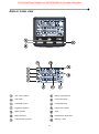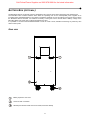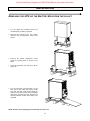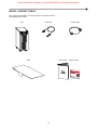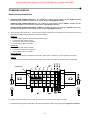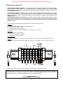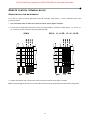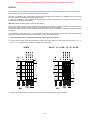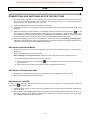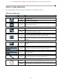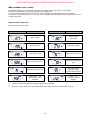
1
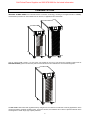
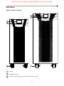
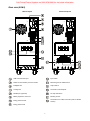
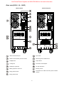
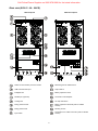
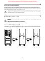
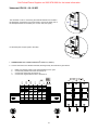
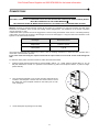
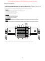
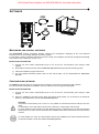
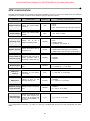
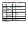
Call Critical Power Supplies on 0800 978 8988 for the latest information 1 Call Critical Power Supplies on 0800 978 8988 for the latest information INTRODUCTION Congratulations on purchasing a UPS Sentinel Power Green product and welcome to Riello UPS! To use the support service offered by Riello UPS, visit the site www.riello-ups.com The company is highly specialised in the development and production of uninterruptible power supplies (UPSs). The UPSs in this series are high-quality products, carefully designed and manufactured in order to ensure the highest levels of performance. This device can be installed by anyone on the condition that he/she has READ THE USER AND SAFETY MANUAL CAREFULLY. The UPS and the Battery Box internally generate DANGEROUS electrical voltages. All maintenance operations must be carried out SOLELY by qualified operators. This manual contains detailed instructions for using and installing the UPS and the Battery box. For information on how to use and maximise the performance of your device, please retain this manual and read it carefully before operating the device. ENVIRONMENTAL PROTECTION In the development of its products, the company devotes abundant resources to analysing the environmental aspects. All our products pursue the objectives defined in the environmental management system developed by the company in compliance with applicable standards. No hazardous materials such as CFCs, HCFCs or asbestos are used in this product. When evaluating packaging, the choice of material has been made favouring recyclable materials. For correct disposal, please separate and identify the type of material of which the packaging is made in the table below. Dispose of all material in compliance with applicable standards in the country in which the product is used. DESCRIPTION MATERIAL Box Cardboard Packaging corner Expanded polystyrene Protective bag Polythene Accessories bag Polythene Pallet Wood + expanded polystyrene Slide Wood DISPOSING OF THE PRODUCT The UPS and the Battery Box contain electronic cards and batteries which are considered TOXIC and HAZARDOUS waste. When the product reaches the end of its operating life, dispose of it in accordance with applicable local legislation. Disposing of the product correctly contributes to respecting the environment and personal health. © The reproduction of any part of this manual, in whole or in part, is forbidden without the prior consent of the manufacturer. In order to make improvements, the manufacturer reserves the right to modify the product described at any moment and without notice. 2 Call Critical Power Supplies on 0800 978 8988 for the latest information CONTENTS PRESENTATION 5 UPS VIEWS 6 FRONT VIEW (ALL MODELS) 6 REAR VIEW (SPM 6) 7 REAR VIEW (SPH 8 - 10 - 10 ER) 8 REAR VIEW (SPH 15 - 20 - 20 ER) 9 DISPLAY PANEL VIEW 10 BATTERY BOX (OPTIONAL) 11 REAR VIEW 11 INSTALLATION 12 REMOVING THE UPS OR THE BATTERY BOX FROM THE PALLET 12 INITIAL CONTENT CHECK 13 INSTALLATION ENVIRONMENT 14 BATTERY BOX INSTALLATION 14 VERSIONS SPM 6, SPH 8 -10 - 10 ER 14 VERSIONS SPH 15 - 20 - 20 ER 15 SETTING THE NOMINAL BATTERY CAPACITY 16 CONNECTIONS 17 SINGLE-PHASE VERSION 18 COMBINED VERSION 19 SINGLE-PHASE CONNECTION 19 THREE-PHASE CONNECTION 20 REMOTE CONTROL TERMINAL BLOCK 21 REMOTE BYPASS FOR MAINTENANCE 21 R.E.P.O. 22 USE 23 CONNECTIONS AND SWITCHING ON FOR THE FIRST TIME 23 SWITCHING ON FROM THE MAINS 23 SWITCHING ON FROM THE BATTERY 23 SWITCHING OFF THE UPS 23 DISPLAY PANEL MESSAGES 24 UPS STATUS MESSAGES 24 MEASUREMENT DISPLAY AREA 25 3 Call Critical Power Supplies on 0800 978 8988 for the latest information CONFIGURING THE OPERATING MODE 27 POSSIBLE SETTINGS 27 ADDITIONAL FUNCTIONS 27 SOFTWARE 29 MONITORING AND CONTROL SOFTWARE 29 CONFIGURATION SOFTWARE 29 UPS CONFIGURATION 30 COMMUNICATION PORTS 32 RS232 CONNECTOR 32 COMMUNICATION SLOT 32 TROUBLESHOOTING 33 ALARM CODES 35 FAULT 35 LOCK 37 TECHNICAL DATA 38 4 Call Critical Power Supplies on 0800 978 8988 for the latest information PRESENTATION SENTINEL POWER GREEN uses ON-LINE double conversion technology, resulting in the highest levels of reliability and maximum protection for critical loads such as servers, IT applications and Voice/Data. Only for versions SPM 6, SPH 8 - 10 and 10 ER, it is possible to use one or more autonomy expansion units known as BATTERY BOXES (optional accessories) with the same dimensions and aesthetic line as the UPS alongside it. The ER model UPSs fitted with upgraded battery chargers are the solution for Business Continuity applications which require long battery-powered operating times. For these versions, the batteries are housed in separate cabinets which are designed to contain large, high-capacity batteries. 5 Call Critical Power Supplies on 0800 978 8988 for the latest information UPS VIEWS FRONT VIEW (ALL MODELS) Display Multipurpose buttons Wheels (front wheels swivel and can be locked, fixed rear wheels) 6 Call Critical Power Supplies on 0800 978 8988 for the latest information REAR VIEW (SPM 6) With backpack Without backpack USB communication port Input switch RS232 communication port and contacts Manual bypass for maintenance Intelligent Slot Output switch Cooling fans Terminals cover backpack Parallel port (optional) Tie wrap hold-down Battery expansion connector Earthing screws Energy Share socket Terminals for I/O cable connection (refer to related section) Energy Share Fuse 7 Call Critical Power Supplies on 0800 978 8988 for the latest information REAR VIEW (SPH 8 - 10 - 10 ER) With backpack Without backpack USB communication port Input switch RS232 communication port and contacts Manual bypass for maintenance Intelligent Slot Output switch Cooling fans Terminals cover backpack Parallel port (optional) Tie wrap hold-down Battery expansion connector Earthing screws Energy Share socket Terminals for I/O cable connection (refer to related section) Energy Share Fuse 8 Call Critical Power Supplies on 0800 978 8988 for the latest information REAR VIEW (SPH 15 - 20 - 20 ER) With backpack Without backpack RS232 communication port and contacts Manual bypass for maintenance USB communication port Output switch Intelligent Slot Battery expansion fuses Parallel port (optional) Terminals cover backpack Cooling fans Tie wrap hold-down Energy Share socket Battery expansion terminals (refer to related section) Energy Share Fuse Earthing screws Input switch Terminals for I/O cable connection (refer to related section) 9 Call Critical Power Supplies on 0800 978 8988 for the latest information DISPLAY PANEL VIEW “SEL” button (Select) Battery charge indicator “ON” button Load level indicator “STAND-BY” button Configuration area Regulation operation Maintenance request Mains operation Timer Battery operation Measurement display area Load powered by bypass Stand-by / alarm 10 Call Critical Power Supplies on 0800 978 8988 for the latest information BATTERY BOX (OPTIONAL) The BATTERY BOX is an optional accessory dedicated to this range of UPSs (same dimensions and aesthetic line). The BATTERY BOX contains batteries which allow the operating time of the uninterruptible power supplies to be increased during extended blackouts. The number of batteries contained can vary according to the type of UPS for which the BATTERY BOX is intended. It is therefore necessary to take great care to ensure that the battery voltage of the BATTERY BOX is the same as the voltage permitted by the UPS. It is possible to connect further BATTERY BOXES in order to create a chain, suitable for achieving any autonomy time without mains power. REAR VIEW Battery expansion connector Screw for earth connection Wheels (front wheels swivel and can be locked, fixed rear wheels) 11 Call Critical Power Supplies on 0800 978 8988 for the latest information INSTALLATION REMOVING THE UPS OR THE BATTERY BOX FROM THE PALLET Cut the straps and carefully remove the cardboard box by sliding it upwards. Remove the accessory box, the wooden slide and the top polystyrene foam corner pieces. Remove the bottom polystyrene corner pieces by rotating them as shown in the figure. Open the protective bag and pull it all the way down. Put the previously removed slide on the back part of the pallet (see figure). Make sure that the slide rests firmly against the pallet so it remains in place during unloading operations. Push the UPS from the front and exercise extreme caution when sliding it off the pallet. NOTE: All parts of the packaging should be kept for future use. 12 Call Critical Power Supplies on 0800 978 8988 for the latest information INITIAL CONTENT CHECK After opening the packaging, it is first necessary to check the contents. The package must contain: UPS USB cable Slide RS232 cable User manual + Safety manual 13 Call Critical Power Supplies on 0800 978 8988 for the latest information INSTALLATION ENVIRONMENT The UPS and the Battery Box must be installed in ventilated, clean environments which are sheltered from bad weather. The relative humidity in the environment must not exceed the maximum values shown in the Technical Data table. The ambient temperature, whilst the UPS is in operation must remain between 0 and 40°C, and the UPS must not be positioned in places which are exposed to direct sunlight or to hot air. The recommended operating temperature for the UPS and the batteries is between 20 and 25°C. The actual operating life of the batteries is 5 years on average with an operating temperature of 20°C. If the operating temperature reaches 30°C, the operating life is halved. BATTERY BOX INSTALLATION CAUTION: CHECK THAT THE BATTERY BOX VOLTAGE IS THE SAME AS THE VOLTAGE PERMITTED BY THE UPS. CHECK THE RATING ON THE BACK OF THE DEVICE. VERSIONS SPM 6, SPH 8 -10 - 10 ER It is possible to connect more than one Battery Box in order to achieve any level of autonomy without mains power. Connect any Battery Boxes in a cascade as shown in the figure below: 14 Call Critical Power Supplies on 0800 978 8988 for the latest information VERSIONS SPH 15 - 20 - 20 ER The terminals to use for connecting the external batteries are located in the backpack. Unscrew the two screws used to secure the lower part of the backpack located on the sides (one on each side, see figure). Lift the back-pack off (see figure to the side). 1. CONNECTION: Use 3 cables with 25 mm section (+, N and -) 2 2. Connect the wires to the relative terminals, following exactly the instructions given below: abcd- Make sure that the isolator of the external battery box is open. Connect the positive branch wire to terminal 11. Connect the neutral wire to terminal 12. Connect the negative branch wire to terminal 13. 15 Call Critical Power Supplies on 0800 978 8988 for the latest information SETTING THE NOMINAL BATTERY CAPACITY Before installing one or more Battery Boxes, configure the UPS to update the rated capacity value (total Ah of batteries in the UPS + external batteries). Use the dedicated UPSTools configuration software, available free of charge at www.riello-ups.com, to perform this operation. The battery box must be installed while the UPS is switched off and disconnected from the main. CAUTION: The connection cables cannot be extended by the user (only for versions SPM 6, SPH 8 - 10 - 10 ER). After connecting the UPS to its Battery Boxes, insert the fuses and turn the Battery Box battery switches to the ON position (only for versions SPH 15 - 20 - 20 ER). It is not possible to connect more than one UPS to a single battery box, or to several Battery Boxes connected in a series. 16 Call Critical Power Supplies on 0800 978 8988 for the latest information CONNECTIONS INSTALLATION MUST ONLY BE PERFORMED BY QUALIFIED PERSONNEL. THE FIRST CONNECTION TO PERFORM IS THAT OF THE PROTECTIVE CONDUCTOR (EARTH CABLE), WHICH MUST BE CONNECTED TO THE SCREW MARKED THE UPS MUST NEVER BE MADE OPERATE WITHOUT A CONNECTION TO THE EARTHING SYSTEM. Warning: providing it complies with the neutral (N) and phase (F) indications for plugs and sockets, the UPS, when inserted in an installation, does not alter the existing neutral arrangements. The resistance on the neutral connection must be less than 0.1 ohm. A differential switch upstream will also be triggered for a fault occurring downstream of the UPS. In calculating reactivity of this switch, account must be taken of the leakage current of the UPS (approx. 2 mA) plus that of the load which come together on the UPS’s earth conductor. UPS input Differential switch Single-phase Type B or Type A Three-phase Type B The neutral arrangements are altered only if there is also an isolating transformer or when the UPS operates with a neutral that is disconnected upstream. In any case avoid connecting the output neutral with the input neutral or to the earth as this could damage the UPS. To make the mains power and load connections, follow the instructions below: 1. Install a magneto-thermal switch (63A for versions SPM 6, SPH 8 - 10 - 10 ER; 125A for versions SPH 15 - 20 - 20 ER) with intervention curve B or C upstream of the machine (4 poles for three-phase versions, 2 poles for singlephase versions). 2. The connection terminals to use for the input and output lines are located in the backpack. Unscrew the two screws used to secure the lower part of the backpack located on the sides (one on each side, see figure). 3. Lift the back-pack off (see figure to the side). 17 Call Critical Power Supplies on 0800 978 8988 for the latest information SINGLE-PHASE VERSION 4. (SINGLE-PHASE CONNECTION SPM 6): use 3 cables with cross-section 6 mm (EARTH, N and L) for the 2 input, and 3 cables with cross-section 6 mm for the output (EARTH, N and L). 2 5. Connect the wires to the relative terminals, following exactly the instructions given below: Input line a - Make sure that the magneto-thermal switch upstream is open. b - Connect the earth wire to screw A. c - Connect the neutral wire to terminal 2. d - Connect the live wire to terminal 1. Output line a - Connect the earth wire to screw B. b - Connect the neutral wire to terminal 3. c - Connect the live wire to terminal 4. Remote By-pass a - Make sure that a jumper is connected between terminals 5 and 6, needed for proper operation of the UPS. R.E.P.O. a - Make sure that a jumper is connected between terminals 7 and 8, needed for proper operation of the UPS. 6. Tighten the terminals well, close the back-pack and secure it with the screws taken out earlier. 18 Call Critical Power Supplies on 0800 978 8988 for the latest information COMBINED VERSION SINGLE-PHASE CONNECTION 4. (SINGLE-PHASE CONNECTION SPH 8 - 10 - 10 ER): use 3 cables of cross-section 10 mm (EARTH, N and L) 2 for the input, and 3 cables of cross-section 10 mm for the output(EARTH, N and L). 2 2 (SINGLE-PHASE CONNECTION SPH 15): use 3 cables of cross-section 16 mm (EARTH, N and L) for the 2 input, and 3 cables of cross-section 16 mm for the output(EARTH, N and L). 2 (SINGLE-PHASE CONNECTION SPH 20 - 20 ER): use 3 cables of cross-section 25 mm (EARTH, N and L) for 2 the input, and 3 cables of cross-section 25 mm for the output(EARTH, N and L). 5. Short-circuit the input terminals (1, 2 and 3) with the jumper provided in the accessories kit. Connect the wires to the respective terminals, following exactly the instructions below: Input line a - Ensure that the upstream magneto-thermal switch is open. b - Connect the earth wire to screw A. c - Connect the neutral wire to terminal 4. d - Connect the live wire to terminal 1. Output line a - Connect the earth wire to screw B. b - Connect the neutral wire to terminal 5. c - Connect the live wire to terminal 6. Remote By-pass a - Ensure that a jumper is connected on terminals 7 and 8, this is necessary for correct operation of the UPS. R.E.P.O. a - Ensure that a jumper is connected on terminals 9 and 10, this is necessary for correct operation of the UPS. JUMPER 6. Tighten the terminals well, close the back-pack and secure it with the screws taken out earlier. 7. Configure the single-phase configuration using the configuration software (see paragraph Configuration software). 19 Call Critical Power Supplies on 0800 978 8988 for the latest information THREE-PHASE CONNECTION 1. (THREE-PHASE CONNECTION SPH 8 - 10 - 10 ER): Use 2 cables of cross-section 4 mm (L2 and L3) and 3 2 with cross-section 10 mm (EARTH, N, L1) for the input (N.B.: L1 and N are of greater cross-section because in bypass operation they have to carry all of the input current). For the output use 3 cables of cross-section 2 10 mm (EARTH, N and L). 2 2 (THREE-PHASE CONNECTION SPH 15): Use 2 cables of cross-section 4 mm (L2 and L3) and 3 of cross2 section 16 mm (EARTH, N, L1) for the input (N.B.: L1 and N are of greater cross-section because in bypass 2 operation they have to carry all of the input current). For the output use 3 cables of cross-section 16 mm (EARTH, N and L). 2 (THREE-PHASE CONNECTION SPH 20): Use 2 cables of cross-section 6 mm (L2 and L3) and 3 of cross2 section 25 mm (EARTH, N, L1) for the input (N.B.: L1 and N are of greater cross-section because in bypass 2 operation they have to carry all of the input current). For the output use 3 cables of cross-section 25 mm (EARTH, N and L). 2. Connect the wires to the respective terminals, following exactly the instructions below: Input line a - Ensure that the upstream magneto-thermal switch is open. b - Connect the earth wire to screw A. c - Connect the neutral wire to terminal 4. d - Connect the wires of the phases to terminals 1, 2 and 3 (for L1 use red wire). Output line a - Connect the earth wire to screw B. b - Connect the neutral wire to terminal 5. c - Connect the live wire to terminal 6. Remote By-pass a - Ensure that a jumper is connected on terminals 7 and 8, this is necessary for correct operation of the UPS. R.E.P.O. a - Ensure that a jumper is connected on terminals 9 and 10, this is necessary for correct operation of the UPS. 3. Tighten the terminals well, close the back-pack and secure it with the screws taken out earlier. A WARNING LABEL MUST BE PUT ON ALL MAINS POWER DISCONNECTING SWITCHES INSTALLED REMOTE FROM THE AREA OF THE UPS, IN ORDER TO ALERT ALL SERVICE OPERATORS THAT THE CIRCUIT IS CONNECTED TO A UPS. THE LABEL MUST BEAR THE FOLLOWING WORDING: ISOLATE THE UPS BEFORE WORKING ON THIS CIRCUIT 20 Call Critical Power Supplies on 0800 978 8988 for the latest information REMOTE CONTROL TERMINAL BLOCK REMOTE BYPASS FOR MAINTENANCE To be able to control the remote maintenance By-Pass externally, follow points 1, 2 and 3 described above. Then proceed as follows: 1. Use a 2x0.75mm cable to make the connection with the remote bypass terminals. 2 2. Connect the two cable leads to terminals 5 and 6 (For version SPM 6), 7 and 8 (For version SPH 8 - 10 - 10 ER - 15 20 - 20 ER) to properly control the remote By-pass externally. SPM 6 SPH 8 - 10 - 10 ER - 15 - 20 - 20 ER 3. Tighten the terminals well, close the back-pack and secure it with the screws taken out earlier. Note: The Remote Bypass function can be used with the UPS in both the single-phase and three-phase configuration. 21 Call Critical Power Supplies on 0800 978 8988 for the latest information R.E.P.O. The terminal block on the back of the UPS also implements the R.E.P.O. (Remote Emergency Power Off) function that can be used to shut off the UPS remotely in case of an emergency. The UPS is provided by the manufacturer with the REPO terminals short-circuited. For installation remove the short circuit and connect to the device's normally closed contact In case of an emergency, if the stop device is used, the REPO control is opened and the UPS goes into stand-by mode and the load is completely disconnected. Attention: before restarting the UPS, reset the stop device. The circuitry of the remote control terminal board is self-powered with SELV circuits. Therefore, an external voltage supply is not required. When a contact is closed, a maximum current of 15mA circulates. All connections with the remote control terminal board are made through a cable which guarantees a double insulation connection. If you would like to bring the R.E.P.O. control outside, unscrew the two screws securing the lower part of the backpack and remove it (as indicated in the section “Connections”). Then, proceed as follows: 1. Use a 2x0.75mm cable to make the connection with the R.E.P.O. terminals. 2 2. Connect the two wires of the cable to terminals 7 and 8 (for version SPM 6), 9 and 10 (for versions SPH 8 - 10 - 10 ER - 15 - 20 - 20 ER) so as to be able to remotely shut off the UPS. SPM 6 SPH 8 - 10 - 10 ER - 15 - 20 - 20 ER 3. Tighten the terminals well, close the back-pack and secure it with the screws taken out earlier. 22 Call Critical Power Supplies on 0800 978 8988 for the latest information USE CONNECTIONS AND SWITCHING ON FOR THE FIRST TIME 1) Check that there is a protection device against overcurrents and short circuits in the system upstream from the UPS. The recommended protection value is 63A (For versions SPM 6, SPH 8 - 10 - 10 ER) and 125A (For versions SPH 15 - 20 - 20 ER) with a B or C trip curve. 2) Close the magnetothermic switch located upstream of the UPS. 3) Press Close the input and output switches and insert the battery fuses (if any) located on the back of the UPS’s backpack. 4) After a few moments, the UPS will switch on, the display will light up, there will be a beep and the icon will start to flash. The UPS is in stand-by mode: meaning that it is only consuming a small amount of power. The microcontroller is powered which supervises the self-diagnoses; the batteries are charging; everything is ready for UPS activation. Battery operation is also in stand-by mode provided that the timer is active. 5) Check which operating mode is set on the display and, if necessary, see the “Configuring operating modes” paragraph to set the required mode. For advanced UPS configurations execute the software UPSTools which can be downloaded from the web site www.riello-ups.com. SWITCHING ON FROM THE MAINS 1) Press the “ON” button for 1 second. After pressing it, all the icons on the display light up for 1 second and the UPS beeps. 1) Switch on the equipment connected to the UPS. When switching on for the first time only: after 30 seconds, check that the UPS is operating correctly: 1) Simulate a blackout by disconnecting power to the UPS. 2) The load must continue to be powered, the every 4 seconds. icon on the display must light up and there must be a beep 3) When power is reconnected, the UPS must go back to operating from the mains. SWITCHING ON FROM THE BATTERY 1) Hold down the “ON” button for at least 5 seconds. All the icons on the display light up for 1 second. 2) Switch on the equipment connected to the UPS. SWITCHING OFF THE UPS In order to switch off the UPS, hold down the “STBY” button for at least 2 seconds. The UPS goes back to stand-by mode and the icon starts to flash: 1) If mains power is present, to switch off the UPS completely open the input isolator and the UPS will shut down after 14 seconds. 2) During battery mode operation with the timer not set, the UPS automatically switches off after 30 seconds. If, on the contrary, the timer is set, press and hold down the “STBY” key for at least 5 seconds to turn off the UPS. For complete shutdown, open the input switch. 23 Call Critical Power Supplies on 0800 978 8988 for the latest information DISPLAY PANEL MESSAGES This chapter describes, in detail, the various information that can be displayed on the LCD. UPS STATUS MESSAGES ICON STATUS Fixed Flashing DESCRIPTION Indicates a fault The UPS is in stand-by mode Fixed Indicates regular operation Fixed The UPS is operating from the mains Flashing The UPS is operating from the mains, but the output voltage is not synchronised with the mains voltage Fixed The UPS is operating from the battery. In this condition, the UPS emits an acoustic signal (beep) at regular 4-second intervals. Flashing Low battery pre-alarm. Indicates that battery autonomy is coming to an end. In this condition, the UPS emits a beep at regular 1-second intervals. Fixed Indicates that the loads connected to the UPS are powered by the bypass Dynamic Indicates the estimated percentage charge of the batteries Dynamic Indicates the percentage of charge applied to the UPS compared with the nominal value. Flashing Maintenance is required. Contact the support centre. Fixed Indicates that the timer is active (programmed switch-on and switch-off). The timer can be activated/deactivated using the software provided. Flashing 1 minute until the UPS switches back on or 3 minutes until it switches off 24 Call Critical Power Supplies on 0800 978 8988 for the latest information MEASUREMENT DISPLAY AREA It is possible to display the most important measurements regarding the UPS in sequence on the display. When the UPS is switched-on, the display shows the main voltage value. To display a different measurement, press the “SEL” button repeatedly until the desired measurement appears. In the event of a fault/alarm (FAULT) or a lock (LOCK), the display will automatically show the type and code of the corresponding alarm. SINGLE-PHASE CONNECTION Some examples are shown below: GRAPHIC EXAMPLE (1) DESCRIPTION GRAPHIC EXAMPLE (1) DESCRIPTION Mains voltage Battery charge percentage Mains frequency Total battery voltage UPS output voltage Applied load percentage Output voltage frequency Current absorbed by the load Residual battery autonomy Temperature of the electronics cooling system inside the UPS Fault / Alarm : the corresponding code is displayed Lock : the corresponding code is displayed (2) (2) (1) The values shown in the images in the table are purely as an indication. (2) The FAULT / LOCK codes can only be displayed if they are active (presence of a fault/alarm or a lock). 25 Call Critical Power Supplies on 0800 978 8988 for the latest information THREE-PHASE CONNECTION Some examples are shown below: GRAPHIC EXAMPLE (1) DESCRIPTION GRAPHIC EXAMPLE (1) DESCRIPTION Percentage of battery charge Voltage phase 1 (2) Voltage phase 2 (2) Battery voltage (4) Voltage phase 3 (2) Battery voltage (4) UPS output voltage Percentage of the applied load Output voltage frequency Current absorbed by the load Residual battery back up time Temperature of the cooling system for the UPS internal electronics Fault/Alarm : the corresponding code is displayed Lock : the corresponding code is displayed (3) (3) (1) The values shown in the images in the table are purely indicative. (2) Alternative indication Phase No./Voltage. (3) The FAULT/LOCK codes can only be displayed if they are active (i.e., if there is a fault/alarm or a lock). (4) Alternating indication, Battery branch no./ Voltage (for versions SPH 15 - 20 - 20 ER) Steady indication, total battery voltage (for versions SPM 6, SPH 8 - 10 - 10 ER) 26 Call Critical Power Supplies on 0800 978 8988 for the latest information CONFIGURING THE OPERATING MODE The area of the display shown in the figure displays the active operating mode and allows the user to choose other modes directly from the display panel. HOW TO PROCEED: To access the configuration area, hold down the “SEL” button for at least 3 seconds. The “SEL” icon on the top right hand side of the display lights up. To change the mode, press the “ON” button. To confirm the mode chosen, hold down the “SEL” button for at least 3 seconds. POSSIBLE SETTINGS The UPS is designed to be configured in various operating modes: (*) ON-LINE is the mode with the greatest load protection and the best quality of the output waveform (*) ECO is the mode with which the UPS consumes the least power, so is therefore the most efficient (**) SMART ACTIVE: in this mode, the UPS decides whether to operate in ON-LINE or ECO mode according to a statistic about the quality of the mains power. STAND-BY OFF [Mode 1]: the UPS operates as an emergency power supply. If mains power is present, the load is not powered, however should the mains supply fail, the load is powered by the UPS. The effective value (rms) of the output frequency and voltage is constantly controlled by the microprocessor, independently from the waveform of the mains voltage, maintaining the output frequency synchronised to the mains within a configurable range. Outside this range, the UPS output de-synchronises from the mains supply, moving to the nominal frequency; in this condition, the UPS cannot use the bypass. (**) In order to optimise performance, in ECO mode, the load is normally powered by the bypass. If the mains goes out of the permitted tolerance range, the UPS switches to ON LINE operation. If the mains returns within the permitted tolerance range for at least five minutes, the UPS goes back to powering the load from the bypass. ADDITIONAL FUNCTIONS MANUAL BYPASS Using the Manual Bypass feature, the UPS can be switched to bypass. In this condition the load is powered directly by the input mains, any disruption in the mains directly affects the load. CAUTION: BEFORE CARRYING OUT THE FOLLOWING SEQUENCE OF OPERATIONS, ENSURE THAT THE UPS’S INPUT AND OUTPUT FREQUENCY COINCIDE AND THAT THE UPS IS NOT OPERATING FROM THE BATTERY Attention: even when the UPS is switched on, the load is disconnected in the event of a mains blackout. If the input mains deviates from the established tolerances, the UPS automatically switches to Stdby mode and disconnects the load. To force the UPS in manual bypass mode, press the ON and SEL key at the same time and hold down for at least 5 seconds or close the manual bypass isolator on the back of the UPS. The code “C05” appears on the display. To return to the normal operation mode press the ON and SEL keys again for at least 4 sec. 27 Call Critical Power Supplies on 0800 978 8988 for the latest information PROGRAMMABLE AUXILIARY SOCKET (EnergyShare) The EnergyShare sockets are outlets that allow for the automatic disconnection of the load applied to them in certain operating conditions. The events that determine automatic disconnection of the EnergyShare sockets can be selected by the user through the UPSTools configuration software. For example, it is possible to select disconnection after a certain period of battery operation; or when the pre-alarm threshold for battery discharge has been reached, or when an overloading event occurs. By default the Energyshare sockets are not configured and therefore function as other outlets. The EnergyShare function is associated with an icon on the display whose meaning is explained in the paragraph entitled “Display panel indications” Note: The maximum output current of EnergyShare sockets is 10A. PARALLEL OPERATION MODE (OPTIONAL) The SENTINEL POWER GREEN range makes it possible to connect up to 2 UPS units in parallel (each with its own battery), allowing redundancy in case of malfunction of one of the two UPS units or to double the power supplied by the UPS system. This function is enabled through a designated kit which is available as an option. The Parallel Kit contains 2 cards to insert in the designated slots (Parallel port, see section “PRESENTATION”) and 2 parallel wires to connect to the card ports. For further information on this function, refer to the Parallel Kit manual or visit www.riello-ups.com 28 Call Critical Power Supplies on 0800 978 8988 for the latest information SOFTWARE MONITORING AND CONTROL SOFTWARE The PowerShield software guarantees effective, intuitive UPS management, displaying all the most important information such as input voltage, applied load, battery capacity. It is also able to perform shutdown operations and send e-mails, text messages and network messages automatically when certain events, selected by the user, occur. 3 INSTALLATION OPERATIONS 1) Connect one of the UPS’s communication ports to one of the PC’s communication ports using the cable supplied. 2) Download the software from the web site www.riello-ups.com selecting the specific operating system. 3) Follow the installation program instructions. 4) For more detailed information please read the user manual which can be downloaded from www.rielloups.com. CONFIGURATION SOFTWARE The UPSTools software allows the configuration and full display of the status of the UPS via USB or RS232. For a list of possible configurations available to the user, refer to the UPS Configuration paragraph. INSTALLATION OPERATIONS 1) Connect one of the UPS’s communication ports to one of the PC’s communication ports using the cable supplied. 2) Follow the installation instructions shown within the software manual which can be located in the UPSTools directory or downloaded from the web site www.riello-ups.com. CAUTION: If the RS232 communication port is used, it is not possible to communicate with the USB port and vice versa. It is advisable to use a cable which is shorter than 3 metres for communication with the UPS. To obtain additional communication ports with different functions, independent from the standard USB and RS232 ports on the UPS, various accessories are available which can be inserted into the communication card slot. To check whether new, more up-to-date software versions are available and for more information about the accessories available, consult the website: www.riello-ups.com. 29 Call Critical Power Supplies on 0800 978 8988 for the latest information UPS CONFIGURATION The table below illustrates all the possible configurations available to the user in order to best adapt the UPS to individual requirements. It is possible to perform these operations using the Upstools software. FUNCTION DESCRIPTION DEFAULT POSSIBLE CONFIGURATIONS Output frequency Selects the nominal output frequency Auto 50 Hz 60 Hz Auto: automatic learning of the input frequency Output voltage Selects the nominal output voltage 230V Operating mode Selects one of the 4 different operating modes ON LINE Bypass operation Selects the mode of use of the bypass line Normal Power-off due to minimum charge Automatic UPS power-off in battery operation mode if the charge is lower than 5% Disabled Enabled Disabled Autonomy limit Maximum battery operation time Disabled Disabled (complete battery discharge) (1 - 65000) sec. in 1 sec steps Battery low warning Estimated autonomy time remaining for the battery low warning 3 min. Battery test Interval of time for the automatic battery test 40 hours Disabled (1 - 1000) h in 1 hour steps Maximum charge alarm threshold Selects the user overcharge limit Disabled Disabled (0 - 103) % in 1% steps Input frequency tolerance range Selects the permitted range for the input frequency for switching to the bypass and for the synchronisation of the output ± 5% 220 - 240 in 1V steps ON LINE ECO SMART ACTIVE STAND-BY OFF (MODE 1) Normal Disabled with input/output synchronisation Disabled without input/output synchronisation (1 - 255) min. in 1 min steps (±3 - ±10) % in 1% steps * For configurations of the Fout = 50, 60Hz or if the sync is disabled with the input, the UPS downgrades the output power. 30 Call Critical Power Supplies on 0800 978 8988 for the latest information FUNCTION DESCRIPTION DEFAULT POSSIBLE CONFIGURATIONS Always connected Always connected Disconnection after no. seconds of battery operation Disconnection after no. seconds of the battery discharge pre-alarm signal ... (see UPStools manual) EnergyShare Select the auxiliary socket operating mode Bypass voltage thresholds Selects the permitted voltage range for switching to the bypass Low: High: 180V 264V Low: 180 - 200 in 1V steps High: 250 - 264 in 1V steps Selects the permitted Bypass voltage voltage range for operation threshold for ECO in ECO mode Low: High: 200V 253V Low: 180 - 220 in 1V steps High: 240 - 264 in 1V steps Intervention sensitivity for ECO Selects the intervention sensitivity during operation in ECO mode Normal Low Normal High Power-on delay Waiting time for automatic switching back on after mains power returns 5 sec. Disabled (1 - 255) sec. in 1 sec steps Remote poweron/off function Selects the function associated with the RS232 connector. Disabled Input configuration three-phase / Single-phase** Selects the Input mains type Three-phase Disabled Remote ON Remote OFF Remote ON/OFF Three-phase Single-phase ** Only for versions SPH 8 - 10 - 10 ER - 15 - 20 - 20 ER. For further information about mains connections, please refer to the relative chapter “Connections” 31 Call Critical Power Supplies on 0800 978 8988 for the latest information COMMUNICATION PORTS On the back of the UPS (see UPS Views), the following communication ports are present: RS232 connector USB connector Expansion slot for additional communication cards RS232 CONNECTOR RS232 CONNECTOR PIN # 1 2 3 4 5 6 7 8 9 SIGNAL Programmable output *: [default: UPS in lock] TXD RXD Programmable input **: [default: disabled] GND Power supply DC (Imax = 20mA) Programmable input **: [default: disabled] Programmable output *: [default: low battery pre-alarm] Programmable output *: [default: battery operation] NOTES (*) Opto-isolated contact max. +30Vdc / 35mA. These contacts can be associated with other events using the software provided (**) Opto-isolated command +5 - 15Vdc. These contacts can be associated with other events using the software provided For further information about interfacing with the UPS, refer to the manual provided COMMUNICATION SLOT The UPS is equipped with an expansion slot for optional communication cards (see figure on right) which allows the device to communicate using the main communication standards. Some examples: Second RS232 and USB port Serial duplicator Ethernet network card with TCP/IP, HTTP and SNMP protocols JBUS / MODBUS protocol converter card PROFIBUS protocol converter card Card with relay isolated contacts To check whether further accessories are available, consult the website: www.riello-ups.com 32 Call Critical Power Supplies on 0800 978 8988 for the latest information TROUBLESHOOTING Irregular UPS operation is most likely not an indication of a fault but due to simple problems or distraction. It is therefore advisable to consult the table below carefully as it summarises information which is useful for solving the most common problems. PROBLEM POSSIBLE CAUSE SOLUTION INPUT SWITCH OPEN Close the input switch located on the back of the UPS.. MAIN CONNECTION CABLE Check that the power cable is connected correctly. MISSING THE DISPLAY DOES NOT LIGHT UP THE DISPLAY IS ON BUT THE LOAD IS NOT POWERED THE UPS IS OPERATING FROM THE BATTERY DESPITE THE PRESENCE OF MAINS VOLTAGE THE DISPLAY SHOWS THE FOLLOW CODE F10 NO MAINS VOLTAGE (BLACKOUT) Check that the power reaches the socket where the UPS is connected (try it with a table lamp, for example). UPSTREAM THERMAL PROTECTION TRIP Reset the thermal protection. CAUTION: Check that there is no output overload to the UPS. THE UPS IS IN STAND-BY MODE Press the “ON” button on the front panel to power the loads. THE STAND-BY OFF MODE IS SELECTED It is necessary to change mode. The STAND-BY OFF (emergency power supply) mode, in fact, only powers the loads in the event of a blackout. NO CONNECTION TO THE LOAD Check the connection to the load. THE INPUT VOLTAGE IS OUTSIDE THE PERMITTED TOLERANCE RANGE FOR MAINS OPERATION Problem with the mains. Wait until the input mains voltage returns within the tolerance range. The UPS will automatically return to mains operation. UPSTREAM THERMAL PROTECTION TRIP Reset the thermal protection. CAUTION: Check that there is no output overload to the UPS. INPUT FUSE FAULTY Switch off and disconnect the UPS from the power supply and contact the support centre. 33 Call Critical Power Supplies on 0800 978 8988 for the latest information PROBLEM THE BUZZER SOUNDS CONTINUOUSLY AND THE DISPLAY SHOWS ONE OF THE FOLLOWING CODES: A54, F50, F51, F52, F53, L50, L51, L52, L53 POSSIBLE CAUSE SOLUTION THE LOAD APPLIED TO THE UPS IS TOO HIGH Reduce the load to within the threshold of 100% (or user threshold in the case of code A54). If the display shows a lock: remove the load and switch the UPS off and back on again. THE DISPLAY SHOWS THE FOLLOW CODE: A62 BATTERIES MISSING OR On the versions with an additional battery charger in BATTERY BOX MISSING OR place of the batteries, check that the Battery Box is NOT CONNECTED inserted and connected to the UPS correctly. THE BUZZER SOUNDS CONTINUOUSLY AND THE DISPLAY SHOWS ONE OF THE FOLLOWING CODES: F20, F21, F22, F40, F43, F96 THE UPS IS If possible, disconnect the power to the load, switch the MALFUNCTIONING; IT WILL UPS off and back on again; if the problem occurs again, PROBABLY LOCK SOON call the support centre. THE BUZZER SOUNDS CONTINUOUSLY AND THE DISPLAY SHOWS ONE OF THE FOLLOWING CODES: F04, L04 THE TEMPERATURE OF THE DISSIPATORS INSIDE THE UPS IS TOO HIGH Check that the temperature of the environment in which the UPS is located does not exceed 40°C. THE BUZZER SOUNDS THERE IS A FAULT ON ONE CONTINUOUSLY AND Disconnect all the utilities, switch the UPS off and back OR MORE OF THE THE DISPLAY SHOWS on again, reconnect the utilities one at a time to identify UTILITIES POWERED BY ONE OF THE FOLLOWING which one is faulty. THE UPS CODES: F53, L53 THE BUZZER SOUNDS CONTINUOUSLY AND THE DISPLAY SHOWS ONE OF THE FOLLOWING CODES: F31, F33, F60, L20, L21, L22, L23, L24, L40, L41, L42, L43, L96 THE UPS IS MALFUNCTIONING If possible, disconnect the power to the load, switch the UPS off and back on again; if the problem occurs again, call the support centre. THE DISPLAY SHOWS ONE OF THE FOLLOWING CODES: C01, C02, C03, C05, C05 A REMOTE COMMAND IS ACTIVE If unwanted, check the status of the command inputs on any optional contact card. THE DISPLAY SHOWS C02 THE MANUAL BYPASS FUNCTION IS ACTIVE To take the UPS out of the manual bypass function, press the ON and SEL keys at the same time and hold them down for at least 4 seconds or open the manual bypass isolator on the back of the UPS. ATTENTION: The UPS in case of a permanent failure will be not able to supply the load. To ensure total protection of your equipment we suggest you install an ATS device (Automatic Transfer Switch) or an external automatic by-pass. For more information visit www.riello-ups.com 34 Call Critical Power Supplies on 0800 978 8988 for the latest information ALARM CODES Using a sophisticated self-diagnosis system, the UPS is able to check its own status and any anomalies and/or faults which may occur during normal operation and display them on the display panel. If there is a problem, the UPS signals the event by showing the code and the type of active alarm on the display (FAULT and/or LOCK). FAULT FAULT alerts can be divided into three categories: Anomalies: these are “minor” problems which do not cause the lock of the UPS but reduce performance or prevent certain functions from being used. CODE DESCRIPTION A04 A12 A14 A15 A30 A50 A54 A62 A64 A90 A91 A93 A94 A95 Fans blocked Cable connection error No neutral (three-phase input) Unbalanced input voltages (three-phase input) E.P.O control active Overload: load > 105% Load percentage greater than the user threshold set Batteries missing or Battery Box missing or not connected Low battery Status of different UPS batteries (parallel UPS configuration) Status of different UPS inputs (parallel UPS configuration) Different UPS operation modes (parallel UPS configuration) Different UPS sizes (parallel UPS configuration) UPS operation mode not set as Online or CVCF (parallel UPS configuration) 35 Call Critical Power Supplies on 0800 978 8988 for the latest information Alarms: these are more critical problems than anomalies because, if they persist, they could cause the UPS to lock in a very short time. CODE DESCRIPTION F04 F07 F10 F20 F21 F22 F31 F32 F33 F40 F41 F43 F50 F51 F52 F53 F60 F65 F92 F96 F97 F98 Dissipator overtemperature Ambient overtemperature Input fuse faulty Capacitor bank undervoltage Capacitor bank overvoltage Unbalanced capacitor bank Output relay stuck (closed) Incorrect PIN setting Back feed alarm active Inverter overvoltage Short circuit Inverter undervoltage Overload: load > 105% Overload: load > 110% Overload: load > 130% Overload: load > 150% Battery overvoltage Battery charge fault Different UPS Bypass Status (present/ not present) (parallel UPS configuration) Negative output power Male parallel cable not connected Female parallel cable not connected Active commands: Indicates the presence of an active remote command. CODE DESCRIPTION C01 C02 C03 C04 C05 Remote control 1 (Switch On/Off) Remote control 2 (load on bypass or manual bypass command) Remote control 3 (Switch On/Off) Battery test in progress Remote control 4 (manual bypass) 36 Call Critical Power Supplies on 0800 978 8988 for the latest information LOCK LOCK alerts are normally preceded by an alarm signal and their scale leads to the power-off of the inverter and the load being powered by the bypass line (this procedure is excluded for locks due to serious, persistent overloads and short circuits). CODE DESCRIPTION L04 L07 L20 L21 L22 L23 L24 L40 L41 L42 L43 L50 L51 L52 L53 L96 L97 L98 Dissipator over temperature Ambient overtemperature Capacitor bank undervoltage Capacitor bank overvoltage Unbalanced capacitor bank Capacitor bank short circuit Failed capacitor bank soft start Inverter overvoltage Short circuit Failed inverter soft start Inverter undervoltage Overload: load > 105% Overload: load > 110% Overload: load > 130% Overload: load > 150% Negative output power Male parallel cable not connected Female parallel cable not connected 37 Call Critical Power Supplies on 0800 978 8988 for the latest information TECHNICAL DATA UPS MODELS SPM 6 SPH 10 SPH 10 ER SPH 8 SPH 20 SPH 20 ER SPH 15 INPUT Nominal voltage [Vac] 220 - 230 - 240 Maximum operating voltage [Vac] Nominal frequency [Hz] (1) [A] Nominal current BATTERY Recharge time (standard versions) Expandability and nominal voltage of the Battery Box Charging current (for ER versions only) 220 - 230 – 240 / 380 – 400 - 415 300 300 / 520 50 - 60 27 45 / 15 (46 / 19 ER) 36 / 13 67 / 23 89 / 30 (90 / 30,5 ER) < 4h for 80% of the load [h] 180Vdc 240Vdc 240Vdc 240 + 240Vdc 240 + 240Vdc Not applicable 8A Not applicable 8A 8A OUTPUT Nominal voltage Frequency (4) [Vac] (2) Selectable: 220 / 230 / 240 Selectable: 220 / 230 / 240 – 380 / 400 / 415 Selectable: 50, 60 or auto sensing [Hz] Nominal power [VA] 6000 8000 10000 15000 20000 Nominal power [W] 5400 6400 9000 13500 18000 Bypass line available: Overload: 100% < load < 110% activates the bypass after 2 seconds locks after 120 seconds locks after 60 seconds Bypass line not available: Bypass line available: Overload: 110% < load < 150% activates the bypass after 2 second locks after 4 seconds locks after 4 seconds Bypass line not available: Bypass line available: Overload load > 150% activates the bypass instantly locks after 1 second locks after 0.5 seconds Bypass line not available: OTHER Leakage current to earth Ambient temperature (3) [mA] < 1,5mA [°C] 0 – 40 Humidity Protection devices Dimensions W x D x H Weight Weight (for ER versions only) Parallel < 2mA < 90% without condensation excessively low batteries - overcurrent - short circuit - overvoltage undervoltage - circuit breaker 350 x 653 x [mm] 262 x 557 x 708 818 [kg] [kg] 62,4 77,7 84,1 (28,1 ER) 146 Not Not Not applicable 18 applicable applicable Max 2 units in parallel configuration with optional kit 157 (48 ER) 25 For more details please consult the web site (1) at nominal load, nominal voltage of 230 Vac, battery charging (2) If the mains frequency is within ±5% of the selected value, the UPS is synchronised with the mains. If the frequency is out of the tolerance range or operating from the battery, the frequency is the one selected ±0.1% (3) 20 - 25 °C for longer battery life (4) To keep the output voltage within the indicated range of precision, recalibration may be necessary after a long period of operation. 38 Call Critical Power Supplies on 0800 978 8988 for the latest information 180VDC 7Ah/ 180VDC 9Ah BATTERY BOX 180VDC 7+7Ah/ 180VDC 9+9Ah 240VDC 7Ah/ 240VDC 9Ah 240VDC 7+7Ah/ 240VDC 9+9Ah Nominal battery voltage [Vdc] 180Vdc 240Vdc Dimensions W x D x H [mm] 262 x 557 x 708 262 x 557 x 708 Weight [kg] 63 / 64,5 39 99 / 102 75 / 77 123 / 127 Call Critical Power Supplies on 0800 978 8988 for the latest information 0MNSPH6K0RU5LUA Call Critical Power Supplies on 0800 978 8988 for the latest information