Transcript
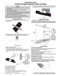
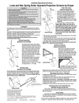
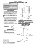
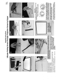
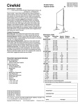
Assembly Instructions
FocalPoint™ Projection Screen by Draper
Caution
① Read instructions through completely before proceeding; retain for future
reference.
② Handle viewing surface with care; do not allow it to come in contact with
sharp or dirty objects.
③ These instructions are based on assembly by a minimum of two people.
④ Make sure screen is level.
⑤ Do not write on viewing surface.
⑥ The ideal temperature range for assembling folding screens to prevent
damaging the surface is 68°-78° F (20°-26° C). Assembling below
recommended temperatures may damage surface and void warranty.
⑦ Do not permit screen fabric to contact border material or loops when
folded. Store in pouch provided.
Patent
Pending
⑦ Attach legs to frame (see Fig. 4) using provided Leg Cranks as follows:
Package A–3 cranks per leg; Package B–4 cranks per leg; and Package
C–5 cranks per leg. Leg Cranks should be placed as follows: 1 at the lowest attachment point, 1 at the highest attachment point, and the rest evenly
spaced between the two.
⑧ Attach viewing surface to frame (see Fig. 5).
Frame/Screen Assembly
Figure 5
① Remove tarp from case and place on the ground.
② Remove frame pieces from case and place in the appropriate locations
on the tarp.
Please Note: For screens with Viewing areas of 18’ or larger Draper
ships a special corner labeled “Large Screen corner”. If you did not
order a complete screen do not use the standard “corner” for the large
screens. Contact Draper if needed.
Please Note: Each piece is color-coded: refer to FocalPoint™ Assembly
Map included with screen for correct layout (see reverse side).
Please Note: Frame pieces should be placed with "forks" running
counter-clockwise and DuraLoop Attachment Lugs facing out.
⑨ Raise FocalPoint into place (this step requires at least two people, depending on screen size) (see Fig. 6).
Figure 6
⑩ Attach the back extensions to the leg bases (see Fig. 7).
Figure 1
③ Assemble frame by inserting "forks" of each piece into extrusions on the
adjoining piece (see Fig. 1). Tighten by turning color-coded attachment
knobs (see Fig. 2).
Figure 7
⑪ If provided, attach Anti-Sway Stabilizers to the frame and legs. First,
unhook the viewing surface from the bottom of the frame near the attachment points. Attach ends with threaded hole through the square extrusion
to the fifth visible hole in from each end of the screen. Attach end with
metal extension to the closest leg extrusion hole (see Fig. 8).
Figure 2
④ Remove leg pieces from case and place in the appropriate locations on
the tarp.
⑤ Assemble leg according to color-coded assembly map by inserting "forks"
of front extension into extrusion on the leg base and tighten color-coded
attachment knobs. Also, attach vertical frame members in the same manner. Do not yet attach the back extension to the leg base (see Fig. 3).
⑥ Place the screen frame on top of the legs (see Fig. 4).
Figure 8
Please Note: You may need to use the built-in adjustment knob to shorten or lengthen the Anti-Sway Stabilizer so it will reach holes (see Fig. 9).
Adjustment
Knob
Figure 3
Figure 9
⑫ If provided, attach HD Leg Braces to frame and legs. Attach ends with
threaded hole through the square extrusion to the frame. Attach end with
metal extension to the back foot extrusion (see Fig. 10).
Figure 4
®
Caution:
Beware of
pinch points.
Figure 10
Warning: This product is intended for indoor use only. Failure to
follow warning may result in product damage or personal injury due to
unforeseen acts of nature.
Copyright © 2012 Draper Inc.
Form FocalPoint_Inst12
Printed in U.S.A.
If you encounter any difficulties assembling your FocalPoint™, call your dealer
or Draper, Inc. in Spiceland, Indiana, 765-987-7999, or fax 765-987-7142.