1
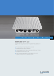
LANCOM OAP-382
Features as of: LCOS 8.80
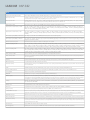
WLAN
Layer-3 Tunneling
Layer-3 Tunneling in conformity with the CAPWAP standard allows the bridging of WLANs per SSID to a separate IP subnet. Layer-2 packets are
encapsulated in Layer-3 tunnels and transported to a LANCOM WLAN controller. By doing this the access point is independent of the present
infrastructure of the network. Possible applications are roaming without changing the IP address and compounding SSIDs without using VLANs.
*) Note
The effective distances and transmission rates that can be achieved are depending of the site RF conditions
IEEE 802.11n Features
MIMO
MIMO technology is a technique which uses multiple transmitters to deliver multiple data streams via different spatial channels. LANCOM uses a
3 x 3 MIMO Configuration where 2 data streams are spread over 3 transmitters. Depending on the existing RF conditions the throughput is doubled
with MIMO technology
40 MHz Channels
Two adjacent 20 MHz channels are combined to create a single 40 MHz channel. Depending on the existing RF Conditions channel bonding doubles
the throughput.
20/40MHz Coexistence Mechanisms in the
2.4GHz Band
Support of coexisting accesspoints with 20 and 40MHz channels in 2.4GHz band.
MAC Aggregation and Block
Acknowledgement
MAC Aggregation increase the 802.11 MAC efficiency by combining MAC data frames and sending it out with a single header. The receiver
acknowledges the combined MAC frame with a Block Acknowledgement. Depending on existing RF conditions, this technique improves throughput
by up to 20%.
Maximal Ratio Combining (MRC)
Maximal Ratio Combining (MRC) enables the receiver (access point), in combination with multiple antennas, to optimally combine MIMO signals
to improve the client reception at long-range.
Short Guard Interval
The guard interval is the time between OFDM symbols in the air. 802.11n gives the option for a shorter 400 nsec guard interval compared to the
legacy 800 nsec guard interval. Under ideal RF conditions this increases the throughput by upto 10%
BFWA*
Support for Broadband Fixed Wireless Access in 5.8 GHz band with up to 4 Watt EIRP for WLAN point-to-point links according to the national
regulations of your country, special antennas required
*) Note
The use of BFWA is subject to country specific regulation
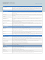
WLAN operating modes
WLAN access point
Infrastructure mode (autonomous operation or managed by LANCOM WLAN Controller)
WLAN bridge
Point-to-multipoint connection of up to 16 Ethernet LANs (mixed operation optional), broken link detection, blind mode, supports VLAN When
configuring Pt-to-Pt links, pre-configured names can be used as an alternative to MAC Adresses for creating a link. Rapid spanning-tree protocol
to support redundant routes in Ethernet networks
WLAN router
Use of the LAN connector for simultaneous DSL over LAN, IP router, NAT/Reverse NAT (IP masquerading) DHCP server, DHCP client, DHCP relay
server, DNS server, PPPoE client (incl.Multi-PPPoE), PPTP client and server, NetBIOS proxy, DynDNS client, NTP, port mapping, policy-based routing
based on routing tags, tagging based on firewall rules, dynamic routing with RIPv2, VRRP
WLAN client
Transparent WLAN client mode for wireless Ethernet extensions, e.g. connecting PCs or printers by Ethernet; up to 64 MAC addresses. Automatic
selection of a WLAN profile (max. 8) with individual access parameters depending on signal strength or priority
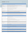
Firewall
Stateful inspection firewall
Incoming/Outgoing Traffic inspection based on connection information. Trigger for firewall rules depending on backup status, e.g. simplified rule
sets for low-bandwidth backup lines. Limitation of the number of sessions per remote site (ID)
Packet filter
Check based on the header information of an IP packet (IP or MAC source/destination addresses; source/destination ports, DiffServ attribute);
remote-site dependant, direction dependant, bandwidth dependant
Extended port forwarding
Network Address Translation (NAT) based on protocol and WAN address, i.e. to make internal webservers accessible from WAN
N:N IP address mapping
N:N IP address mapping for translation of IP addresses or entire networks
Tagging
The firewall marks packets with routing tags, e.g. for policy-based routing
Actions
Forward, drop, reject, block sender address, close destination port, disconnect
Notification
Via e-mail, SYSLOG or SNMP trap
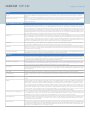
Quality of Service
Traffic shaping
Dynamic bandwidth management with IP traffic shaping
Bandwidth reservation
Dynamic reservation of minimum and maximum bandwidths, totally or connection based, separate settings for send and receive directions. Setting
relative bandwidth limits for QoS in percent
DiffServ/TOS
Priority queuing of packets based on DiffServ/TOS fields
Packet-size control
Automatic packet-size control by fragmentation or Path Maximum Transmission Unit (PMTU) adjustment
Layer 2/Layer 3 tagging
Automatic or fixed translation of layer-2 priority information (IEEE 802.11p-marked Ethernet frames) to layer-3 DiffServ attributes in routing mode.
Translation from layer 3 to layer 2 with automatic recognition of 802.1p-support in the destination device