1
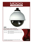
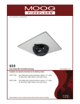
© 2011, Moog Videolarm, Inc. All Rights Reserved
IR200-36 and IR100-36
InfraRed Illuminator
www.videolarm.com
Installation and Operation Instructions for the following models:
IR200-36
850NM Adjustable IR Illuminator, 30, 45, or 60 Degree Angle, 30-200M Distance. 18-24V Input with Surge Protection.
IR100-36N Fully adjustable infrared illuminator- 940 nanometer beam for covert surveillance (untraceable by human eye). 30-100M distance.
Before attempting to connect or operate this product, please read these instructions completely.
81-IN5396
01-11-2012
IMPORTANT SAFEGUARDS
1
Read these instructions.
2
Keep these instructions.
3
Heed all warnings
4
Follow all instructions.
5
Do not use this apparatus near water.
6
Clean only with damp cloth.
7
CAUTION
RISK OF ELECTRIC SHOCK
DO NOT OPEN
Do not block any of the ventilation openings. Install in accordance with the
manufacturers instructions.
8
9
SAFETY PRECAUTIONS
Cable Runs- All cable runs must be within permissible distance.
CAUTION: TO REDUCE THE RISK OF
ELECTRIC SHOCK, DO NOT REMOVE
COVER ( OR BACK). NO USER- SERVICEABLE PARTS INSIDE. REFER SEVICING
TO QUALIFIED SERVICE PERSONNEL.
Mounting - This unit must be properly and securely mounted to a supporting
structure capable of sustaining the weight of the unit.
Accordingly:
a. The installation should be made by a qualified installer.
b. The installation should be in compliance with local codes.
c. Care should be exercised to select suitable hardware to install the unit, taking into
account both the composition of the mounting surface and the weight of the unit.
10 Do not install near any heat sources such as radiators, heat registers, stoves, or other
apparatus ( including amplifiers) that produce heat.
11 Do not defeat the safety purpose of the polarized or grounding-type plug. A
polarized plug has two blades with one wider than the other. A grounding type
plug has two blades and a third grounding prong. The wide blade or the third
prong are provided for your safety. When the provided plug does not fit into your
outlet, consult an electrician for replacement of the obsolete outlet.
12 Protect the power cord from being walked on or pinched particularly at plugs,
convenience receptacles, and the point where they exit from the apparatus.
13 Only use attachment/ accessories specified by the manufacturer.
14 Use only with a cart, stand, tripod, bracket, or table specified by the manufacturer,
or sold with the apparatus. When a cart is used, use caution when moving the cart/
apparatus combination to avoid injury from tip-over.
15 Unplug this apparatus during lighting storms or when unused for long periods of time.
16 Refer all servicing to qualified service personnel. Servicing is required when the
apparatus has been damaged in any way, such as power-supply cord or plug is
damaged, liquid has been spilled of objects have fallen into the apparatus, the
The lightning flash with an arrowhead symbol,
within an equilateral triangle, is intended to
alert the user to the presence of non-insulated
“dangerous voltage” within the product’s
enclosure that may be of sufficient magnitude
to constitute a risk to persons.
Este símbolo se piensa para alertar al usuario a la presencia
del “voltaje peligroso no-aisIado” dentro del recinto de los
productos que puede ser un riesgo de choque eléctrico.
Ce symbole est prévu pour alerter I’utilisateur à la presence
“de la tension dangereuse” non-isolée dans la clôture de
produits qui peut être un risque de choc électrique.
Dieses Symbol soll den Benutzer zum Vorhandensein der
nicht-lsolier “Gefährdungsspannung” innerhalb der
Produkteinschließung alarmieren die eine Gefahr des
elektrischen Schlages sein kann.
Este símbolo é pretendido alertar o usuário à presença “di
tensão perigosa non-isolada” dentro do cerco dos produtos
que pode ser um risco de choque elétrico.
Questo simbolo è inteso per avvertire I’utente alla presenza
“di tensione pericolosa” non-isolata all’interno della
recinzione dei prodotti che può essere un rischio di scossa
elettrica.
apparatus has been exposed to rain or moisture, does not operate normally, or
has been dropped.
Be sure to periodically examine the unit and the supporting structure to make sure that the integrity
of the installation is intact. Failure to comply with the foregoing could result in the unit separating
from the support structure and falling, with resultant damages or injury to anyone or anything struck
by the falling unit.
UNPACKING
Unpack carefully. Electronic components can be
damaged if improperly handled or dropped. If an item
appears to have been damaged in shipment, replace
it properly in its carton and notify the shipper.
Be sure to save:
1 The shipping carton and packaging material.
They are the safest material in which to make future
shipments of the equipment.
2 These Installation and Operating Instructions.
SERVICE
If technical support or service is needed, contact us at
the following number:
TECHNICAL SUPPORT
AVAILABLE 24 HOURS
1 - 800 - 554 -1124
The exclamation point within an equilateral
triangle is intended to alert the user to
presence of important operating and
maintenance (servicing) instructions in the
literature accompanying the appliance.
Este símbolo del punto del exclamation se piensa para
alertar al usuario a la presencia de instrucciones importantes
en la literatura que acompaña la aplicación.
Ce symbole de point d’exclamation est prévu pour alerter
l’utilisateur à la presence des instructions importantes dans
la littérature accompagnant l’appareil.
Dieses Ausruf Punktsymbol soll den Benutzer zum
Vorhandensein de wichtigen Anweisungen in der Literatur
alarmieren, die das Gerät begleitet.
Este símbolo do ponto do exclamation é pretendido alertar o
usuário à presença de instruções importantes na literatura
que acompanha o dispositivo.
Questo simbolo del punto del exclamaton è inteso per
avvertire l’utente alla presenza delle istruzioni importanti nella
letteratura che accompagna l'apparecchio.
Limited Warranty for Moog Videolarm Products
Moog Videolarm warrants these products to be free from defects in material or workmanship as follows:
PRODUCT CATEGORY
PARTS \ LABOR
AllEnclosuresandElectronics*
Five(5)Years
Poles/PolEvators™/CamEvator
Three(3)Years
WarriorSeries™/Q-View™/IRIlluminators
Five(5)Years
SViewSeries™
Five(5)Years**6monthsifusedinautoscan/touroperation
Controllers
Five(5)Years
PowerSupplies
Five(5)Years
EcoKit
Three(3)Years
AccessoryBrackets
Five(5)Years
LibertyDome
Three(3)Years
*DeputyDome™,NiteTrac™,IglooDome,PurgeDome™
Three(3)Years**6monthsifusedinautoscan/touroperation
During the labor warranty period, to repair the Product, Purchaser will either return the defective product, freight prepaid, or deliver it to Moog Videolarm
Inc. Decatur GA. The Product to be repaired is to be returned in either its original carton or a similar package affording an equal degree of protection with
a RMA # (Return Materials Authorization number) displayed on the outer box or packing slip. To obtain a RMA# you must contact our Technical Support
Team at 800.554.1124, extension 101. Moog Videolarm will return the repaired Product freight prepaid to Purchaser. Moog Videolarm is not obligated to
provide Purchaser with a substitute unit during the warranty period or at any time. After the applicable warranty period, Purchaser must pay all labor and/or
parts charges.
The limited warranty stated in these product instructions is subject to all of the following terms and conditions.
TERMS AND CONDITIONS
1. NOTIFICATION OF CLAIMS: WARRANTY SERVICE: If Purchaser believes that the Product is defective in material or workmanship, then written notice with an
explanation of the claim shall be given promptly by Purchaser to Moog Videolarm. All claims for warranty service must be made within the warranty period.
If after investigation Moog Videolarm determines the reported problem was not covered by the warranty, Purchaser shall pay Moog Videolarm for the cost of
investigating the problem at its then prevailing per incident billable rate. No repair or replacement of any Product or part thereof shall extend the warranty period
of the entire Product. The specific warranty on the repaired part only shall be in effect for a period of ninety (90) days following the repair or replacement of that
part or the remaining period of the Product parts warranty, whichever is greater.
2. EXCLUSIVE REMEDY: ACCEPTANCE: Purchaser’s exclusive remedy and Moog Videolarm’s sole obligation is to supply (or pay for) all labor necessary to repair any
Product found to be defective within the warranty period and to supply, at no extra charge, new or rebuilt replacements for defective parts.
3. EXCEPTIONS TO LIMITED WARRANTY:Moog Videolarm shall have no liability or obligation to Purchaser with respect to any Product requiring service during the
warranty period which is subjected to any of the following: abuse, improper use, negligence, accident, lightning damage or other acts of God (i.e., hurricanes,
earthquakes), modification, failure of the end-user to follow the directions outlined in the product instructions, failure of the end-user to follow the maintenance
procedures recommended by the International Security Industry Organization, written in product instructions, or recommended in the service manual for the
Product. Furthermore, Moog Videolarm shall have no liability where a schedule is specified for regular replacement or maintenance or cleaning of certain parts
(based on usage) and the end-user has failed to follow such schedule; attempted repair by non-qualified personnel; operation of the Product outside of the
published environmental and electrical parameters, or if such Product’s original identification (trademark, serial number) markings have been defaced, altered,
or removed. Moog Videolarm excludes from warranty coverage Products sold AS IS and/or WITH ALL FAULTS and excludes used Products which have not
been sold by Moog Videolarm to the Purchaser. All software and accompanying documentation furnished with, or as part of the Product is furnished “AS IS”
(i.e., without any warranty of any kind), except where expressly provided otherwise in any documentation or license agreement furnished with the Product. Any
cost associated with removal of defective product and installation of replacement product is not included in this warranty.
4. PROOF OF PURCHASE:The Purchaser’s dated bill of sale must be retained as evidence of the date of purchase and to establish warranty eligibility.
DISCLAIMER OF WARRANTY
EXCEPT FOR THE FOREGOING WARRANTIES, Moog Videolarm HEREBY DISCLAIMS AND EXCLUDES ALL OTHER WARRANTIES, EXPRESS OR IMPLIED,
INCLUDING, BUT NOT LIMITED TO ANY AND/OR ALL IMPLIED WARRANTIES OF MERCHANTABILITY, FITNESS FOR A PARTICULAR PURPOSE AND/OR
ANY WARRANTY WITH REGARD TO ANY CLAIM OF INFRINGEMENT THAT MAY BE PROVIDED IN SECTION 2-312(3) OF THE UNIFORM COMMERCIAL
CODE AND/OR IN ANY OTHER COMPARABLE STATE STATUTE. Moog Videolarm HEREBY DISCLAIMS ANY REPRESENTATIONS OR WARRANTY THAT
THE PRODUCT IS COMPATIBLE WITH ANY COMBINATION OF NON-Moog Videolarm PRODUCTS OR NON-Moog Videolarm RECOMMENDED PRODUCTS
PURCHASER MAY CHOOSE TO CONNECT TO THE PRODUCT.
LIMITATION OF LIABILITY
THE LIABILITY OF Moog Videolarm, IF ANY, AND PURCHASER’S SOLE AND EXCLUSIVE REMEDY FOR DAMAGES FOR ANY CLAIM OF ANY KIND
WHATSOEVER, REGARDLESS OF THE LEGAL THEORY AND WHETHER ARISING IN TORT OR CONTRACT, SHALL NOT BE GREATER THAN THE ACTUAL
PURCHASE PRICE OF THE PRODUCT WITH RESPECT TO WHICH SUCH CLAIM IS MADE. IN NO EVENT SHALL Moog Videolarm BE LIABLE TO PURCHASER
FOR ANY SPECIAL, INDIRECT, INCIDENTAL, OR CONSEQUENTIAL DAMAGES OF ANY KIND INCLUDING, BUT NOT LIMITED TO, COMPENSATION,
REIMBURSEMENT OR DAMAGES ON ACCOUNT OF THE LOSS OF PRESENT OR PROSPECTIVE PROFITS OR FOR ANY OTHER REASON WHATSOEVER.
!
Electrical Specifications
Power 24VAC
Class 2 Only
English
IR200-36 (OUTDOOR ONLY)
IR100-36N
24 VAC
1.8 Amps
15-42 Watts
(18 V - 24V AC/DC)
Tools Required:
.100” Flat Head Screwdriver
Phillips Head Screwdriver
Loctite Threadlocker
CATION: Do Not Stare directly into the LED Module during
Installation.
(AL AIRE LIBRE SOLAMENTE)
IR200-36
24 VAC
1.8 Amperios
15-42 Vatios
(18 V - 24V AC/DC)
Español
Herramientas Requeridas: Loctite Principal Phillips Thread
locker Del Destornillador Del Destornillador
Principal Plano Del 100"
CATIÓN: No mire fijamente directamente en el módulo del LED
durante la instalación.
(EXTÉRIEUR SEULEMENT)
IR200-36
24 VCA
1.8 Ampère
15-42 Watts
(18 V- 24V AC/DC)
Français
Les Outils Ont exigé : Loctite Principal Phillips Threadlocker
De Tournevis De Tournevis Principal Plat
De 100"
CATION : Ne regardez pas fixement directement dans le module de
LED pendant l'installation.
(IM FREIEN NUR)
IR200-36
24 VAC
1.8 Ampere
15-42 Watt
(18 V - 24V AC/DC)
Deutsch
Werkzeuge Erforderten: 100"Flacher HauptschraubenzieherKreuzkopfhauptschraubenzieher-Loctite
Threadlocker
KATION: Starren Sie nicht direkt in das LED Modul während der
Installation an.
(AO AR LIVRE SOMENTE)
IR200-36
24 VAC
1.8 Ampère
15-42 Watts
(18 V - 24V AC/DC)
Portuguese
Ferramentas Requeridas: Loctite Principal Phillips Thread
locker Da Chave de fenda Da Chave de
fenda Principal Lisa Do 100"
CATION: Não olhe fixamente diretamente no módulo do diodo
emissor de luz durante a instalação.
(ESTERNO SOLTANTO)
IR200-36
24 VCA
1.8 Ampère
15-42 Watt
Italiano
(18 V - 24V AC/DC)
Attrezzi Richiesti: Loctite Capo "phillips" Threadlocker Del
Cacciavite Del Cacciavite Capo Piano
Del 100""
CATIONE: Non stare direttamente nel modulo del LED durante
l'installazione.
3
Content of Box
1a
2a
352'-1
107.32 m
The beam angle may be adjusted to 30º
on the bottom of the unit.
This is the typical light pattern with the 30
degree adjustment.
• El ángulo de haz se puede ajustar a 30º en el
fondo de la unidad.
• L'angle de faisceau peut être ajusté sur 30º sur le
fond de l'unité.
• Der Strahlungswinkel kann bis 30º auf der Unterseite der Maßeinheit justiert werden.
• O ângulo de feixe pode ser ajustado a 30º no
fundo da unidade.
• L'angolo a fascio può essere registrato a 30º sulla
parte inferiore dell'unità.
• Éste es el patrón ligero típico en con los 30 ajustes
del grado.
• C'est le modèle léger typique avec les 30 ajustements de degré.
• Dieses ist das typische helle Muster mit der 30
Gradjustage.
• Este é o teste padrão claro típico com os 30
ajustes do grau.
• Ciò è il modello chiaro tipico con le 30 registrazioni di grado.
3a
IR ILLUMINATION WITH 30
DEGREE ADJUSTMENT
This is what the typical path of illumination will look like with the setting at 30 degrees.
• Esto es lo que parecerá la trayectoria típica de la iluminación con el ajuste 30 grados.
• C'est ce qui ressemblera le chemin typique de l'illumination à avec l'arrangement 30 degrés.
• Dieses ist, was der typische Weg der Ablichtung wie mit der Einstellung bei 30 Grad aussieht.
• Este é o que o trajeto típico da iluminação olhará como com o ajuste em 30 graus.
• Ciò è che cosa il percorso tipico di illuminazione assomiglierà con alla regolazione 30 gradi
2b
1b
The beam angle may be adjusted to 45º on
the bottom of the unit.
• El ángulo de haz se puede ajustar a 45º en el fondo
de la unidad.
• L'angle de faisceau peut être ajusté sur 45º sur le fond
de l'unité.
• Der Strahlungswinkel kann bis 45º auf der Unterseite
der Maßeinheit justiert werden.
• O ângulo de feixe pode ser ajustado a 45º no fundo
da unidade.
• L'angolo a fascio può essere registrato a 45º sulla
parte inferiore dell'unità.
This is the typical light pattern with the 45
degree adjustment.
• Éste es el patrón ligero típico con los 45 ajustes del
grado.
• C'est le modèle léger typique avec les 45 ajustements
de degré.
• Dieses ist das typische helle Muster mit der 45 Gradjustage.
• Este é o teste padrão claro típico com os 45 ajustes do
grau.
• Ciò è il modello chiaro tipico con le 45 registrazioni di
grado.
3b
This is what the typical path of illumination will look like with the setting at 45 degrees.
• Esto es lo que parecerá la trayectoria típica de la iluminación con el ajuste 45 grados.
• C'est ce qui ressemblera le chemin typique de l'illumination à avec l'arrangement 45 degrés.
• Dieses ist, was der typische Weg der Ablichtung wie mit der Einstellung bei 45 Grad aussieht.
• Este é o que o trajeto típico da iluminação olhará como com o ajuste em 45 graus.
• Ciò è che cosa il percorso tipico di illuminazione assomiglierà con alla regolazione 45 gradi
1c
2c
352'-1
107.32
679'-2"
207.
01m
The beam angle may be adjusted to 60º on
the bottom of the unit.
• El ángulo de haz se puede ajustar a 60º en el fondo
de la unidad.
• L'angle de faisceau peut être ajusté sur 60º sur le fond
de l'unité.
• Der Strahlungswinkel kann bis 60º auf der Unterseite
der Maßeinheit justiert werden.
• O ângulo de feixe pode ser ajustado a 60º no fundo
da unidade.
• L'angolo a fascio può essere registrato a 60º sulla
parte inferiore dell'unità.
This is the typical light pattern with the 60
degree adjustment.
• Éste es el patrón ligero típico con los 60 ajustes del
grado.
• C'est le modèle léger typique avec les 60 ajustements
de degré.
• Dieses ist das typische helle Muster mit der 60 Gradjustage.
• Este é o teste padrão claro típico com os 60 ajustes
do grau.
• Ciò è il modello chiaro tipico con le 60 registrazioni di
grado.
3c
IR ILLUMINATION WITH 60
DEGREE ADJUSTMENT
This is what the typical path of illumination will look like with the setting at 60 degrees.
• Esto es lo que parecerá la trayectoria típica de la iluminación con el ajuste 60 grados.
• C'est ce qui ressemblera le chemin typique de l'illumination à avec l'arrangement 60 degrés.
• Dieses ist, was der typische Weg der Ablichtung wie mit der Einstellung bei 60 Grad aussieht.
• Este é o que o trajeto típico da iluminação olhará como com o ajuste em 60 graus.
• Ciò è che cosa il percorso tipico di illuminazione assomiglierà con alla regolazione 60 gradi.
4
IR+PV6 Mount
IR+P&T Mount
IR+WM800 Mount
These are the typical mounting configurations for the IR illuminator.
• Éstas son las configuraciones típicas para el iluminador IR.
• Ce sont les configurations typiques pour le bloc d'éclairage IR
• Diese sind die typischen Konfigurationen für die IR Belichtungseinheit.
• Estas são as configurações típicas para o iluminador IR.
• Queste sono le configurazioni tipiche per la lampadina IR.
5
6
High
Power
Setting
Medium Power
Setting
Low Power Setting
The hardware and mounting surface must
support bracket weight plus IR illuminator.
• El hardware y la superficie de montaje deben apoyar el
•
•
•
•
peso del soporte más el iluminador IR.
Le matériel et la surface de montage doivent soutenir le
poids de la parenthèse plus le bloc d'éclairage IR.
Le matériel et la surface de montage doivent soutenir le
poids de la parenthèse plus le bloc d'éclairage IR.
A ferragem e a superfície de montagem devem
suportar o peso do suporte mais o iluminador IR.
I fissaggi e la superficie di montaggio devono sostenere
il peso della staffa più la lampadina IR. inferiore
dell'unità.
The power switch on the back of the unit
has (3) settings: high, medium, and low.
• El interruptor en la parte posteriora de la unidad tiene (3)
ajustes: alto, medio, y bajo.
• Le passage de puissance sur le dos de l'unité a (3) des
arrangements : haut, moyen, et bas.
• Der Energie Schalter auf der Rückseite der Maßeinheit hat (3)
Einstellungen: hoch, mittlere und niedrig.
• O interruptor de poder na parte traseira da unidade tem (3)
ajustes: elevado, médio, e baixo.
• L'interruttore di alimentazione sulla parte posteriore dell'unità
ha (3) regolazioni: alto, medio e basso. dell'unità.
7
English
Español
Estimated Illuminated Distances*
30 - 60 Meters: 60° at Low Power Setting
60 - 100 Meters: 45° at Medium Power Setting
100+ Meters: 30° at High Power Setting
Deutsch
* Abschließende Einstellungen hängen von der verwendeten
Anwendung ab, Klima- und Überwachungkamera. IR200-36
liefert mehrere Energie Einstellung und Strahlungswinkelbe
trachtung Wahlen, um Ihre Anwendung besser zu belichten.
Es wird empfohlen, um jede Einstellung manuell zu prüfen
(Energie oder Strahlungswinkel) um festzustellen was
für Ihre sofortigen Notwendigkeiten am besten ist.
*Final settings will depend on application, environment
and surveillance camera utilized. IR200-36 provides
several power setting and beam angle viewing
options to better illuminate your application. It is
recommended to manually test each setting (power
or beam angle) to determine what’s best for your
immediate needs.
Distancias Iluminadas Estimadas *
30 - 60 Metros: 60° en el ajuste bajo de la energía.
60 - 100 metros: 45° en el ajuste medio de la energía.
metros 100+: 30° en el ajuste de la alta energía.
Portuguese
* Los ajustes finales dependerán de la cámara fotográfica del uso, del
ambiente y de la vigilancia utilizada. IR200-36 proporciona varios las opciones
de la visión del ángulo del ajuste y de haz de la energía para iluminar mejor su
uso. Se recomienda para probar manualmente cada ajuste (ángulo de la
energía o de haz) para determinarse cuál es el mejor para sus necesidades
inmediatas.
Français
Distances Lumineuses Estimées *
30 - 60 Mètres : 60° au bas arrangement de puissance.
60 - 100 mètres : 45° à l'arrangement moyen de puissance.
mètres 100+ : 30° à l'arrangement de puissance élevée.
Italiano
* Les arrangements finals dépendront de l'appareil-photo
d'application, d'environnement et de surveillance utilisé. IR200-36
fournit plusieurs arrangement de puissance et options de
visionnement d'angle de faisceau pour illuminer mieux votre
application. On lui recommande d'examiner manuellement
chaque arrangement (puissance ou angle de faisceau) pour
déterminer ce qui est le meilleur pour vos besoins immédiats.
8
To maintain the unit remove the (4) screws
located on the face.
• Al mantenimiento la unidad quita (4) los tornillos
situados en la cara.
• Sur l'entretien l'unité enlèvent (4) les vis plac sur le
visage.
• Zur Wartung entfernen die Maßeinheit die (4)
Schrauben, die auf dem Gesicht gelegen sind.
• À manutenção a unidade remove (4) os parafusos
posicionados na cara.
• A manutenzione l'unità rimuove (4) le viti posizionate
sulla faccia.
Geschätzte Belichtete Abstände *
30 - 60 Meter: 60° an der niedrigen Energie Einstellung.
60 - 100 Meter: 45° an der mittleren Energie Einstellung.
Meßinstrumente 100+: 30° an der hohe Energie Einstellung.
Distâncias Iluminadas Estimadas *
30 - 60 Medidores: 60° no ajuste baixo do poder.
60 - 100 medidores: 45° no ajuste médio do poder.
medidores 100+: 30° no ajuste do poder elevado.
* Os ajustes finais dependerão da câmera da aplicação, do
ambiente e do surveillance utilizada. IR200-36 fornece
diversos opções da visão do ângulo do ajuste e de feixe do
poder para iluminar mais melhor sua aplicação.
Recomenda-se testar manualmente cada ajuste (ângulo do
poder ou de feixe) para determinar o que é o mais melhor
para suas necessidades imediatas.
Distanze Illuminate Valutate *
30 - 60 Tester: 60° alla regolazione bassa di alimentazione.
60 - 100 tester: 45° alla regolazione media dialimentazone.
tester 100+: 30° alla regolazione di alta alimentazione.
* Le regolazioni finali dipenderanno dalla macchina
fotografica di applicazione, dell'ambiente e di
sorveglianza utilizzata. IR200-36 fornisce vari la
regolazione di alimentazione ed opzioni di osservazione di
angolo a fascio per illuminare più meglio la vostra applicazi
one. È suggerito per verificare manualmente ogni regolazi
one (alimentazione o angolo a fascio) per determinare che
cosa è il la cosa migliore per i vostri bisogni immediati.
9
Rotate the face 180 degrees.
• Rote la cara 180 grados.
• Tournez le visage 180 degrés.
• Drehen Sie das Gesicht 180 Grad.
• Gire a cara 180 graus.
• Ruoti la faccia 180 gradi.
10
The internal parts are attached by a
lanyard in the back of the unit.
11
Slide the electronic components out
of the housing on the sled.
• Las piezas internas son unidas por un acollador en
la parte posteriora de la unidad.
• Les pièces internes sont attachées par une lanière
dans le dos de l'unité.
• Die internen Teile werden durch eine Abzuglinie in
der Rückseite der Maßeinheit angebracht.
• As peças internas são unidas por um colhedor na
parte traseira da unidade.
• Le parti interne sono fissate da una cordicella
nella parte posteriore dell'unità.
• Resbale los componentes electrónicos de la
cubierta en el trineo.
• Glissez les composants électroniques hors du
logement sur le traîneau.
• Schieben Sie die elektronischen Bauelemente aus
dem Gehäuse auf dem Schlitten heraus.
• Deslize os componentes eletrônicos fora da
carcaça no trenó.
• Faccia scorrere i componenti elettronici
dall'alloggiamento sulla slitta.
12
13
Fuse Cradle
Remove the defective fuse from the
circuit board.
• Quite el fusible defectuoso del tablero de
circuito.
• Enlevez le fusible défectueux de la carte.
• Entfernen Sie die defekte Sicherung von der
Leiterplatte.
Position the new fuse in the cradle.
• Coloque el fusible nuevo en la horquilla.
• Placez le nouveau fusible dans le berceau.
• Der Strahlungswinkel kann auf der Unterseite der
Maßeinheit justiert werden.
• Remova o fusível defeituoso da placa de circuito.
• Posicione o fusível novo no berço.
• Rimuova il fusibile difettoso dal bordo del circuito.
• Posizioni il nuovo fusibile nella culla.
14
Power and Control Leads
(+)
(-)
Black
White
Positive
Negative
24VAC
18VDC
Wiring the IR200-36/ IR100-36N can be completed by referring to the following diagram.
• Atar con alambre el IR200-36/ IR100-36N puede ser terminada refiriendo al diagrama siguiente.
• Le câblage de l'IR200-36/ IR100-36N peut être accompli en se rapportant au diagramme suivant.
• Das Verdrahten des IR200-36/ IR100-36N kann durchgeführt werden, indem man auf das folgende Diagramm sich
bezieht.
• Wiring o IR200-36/ IR100-36N pode ser terminado consultando ao seguinte diagrama.
• Legare il IR200-36/ IR100-36N può essere completato riferendosi al seguente schema.
13
12
14
11
10
IR 200-36
Replacement Parts List
8
6
9
7
5
4
2
HOUS ING
HOUS ING F AN
R P IR 030
R P F D080
R P IR 040
R P IR 050
R P IR 060
4
5
6
7
8
F R ONT M EC HANIS M
R P IR 0100
13
1
3
R P IR 0110
R P IR 090
12
14
R P 96GK2765 B AC K S EALING
11
S WITC H
1
C ONDUIT S ET
B AC K C OVER
M OUNTING B LOC K
R P IR 070
R P IR 080
9
10
B AS E B R AC KET
P OWER B OAR D
12V DC B LOWER
F AN B R AC KET
LED B OAR DS
R P IR 010
R P IR 020
2
3
R P 40VL2991 F R ONT C OVER AS S EM B LY
DES C R IP TION
P AR T #
1
PART LIST
LIS T#
Product Registration/Warranty
Thank you for choosing Moog Videolarm. We value your patronage and are solely committed to providing you with the highest
quality products available and superior customer service. Should a problem arise, rest assure that Moog Videolarm stands behind its products by offering impressive warranty plans: 3 Years on all Housings, Poles, Power Supplies, and Accessories and 5 Years on camera systems (SView, QView, Warriors), and InfraRed Illuminators.
Register Your Products Online
Take a few moments and validate your purchase via the Online Product Registration Form at
www.videolarm.com/productregistration.jsp
Register your recent Moog Videolarm purchases and benefit from the following:
• Simple and Trouble-Free RMA process
• Added into customer database to receive product updates / news
• Eliminate the need to archive original purchase documents:
Receipts, Purchase Orders, etc…