1
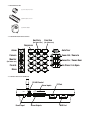
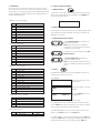
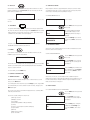
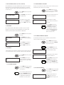
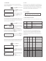
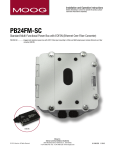
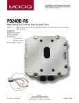
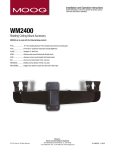
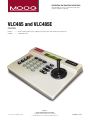
Installation and Operation Instructions
Before attempting to connect or operate this product, please
read these instructions completely.
VLC485 and VLC485E
Controller
VLC485.....................RS485 controller (2) RS232 ports (1) RS485 port, joystick control. Desk top model, 24Vac input power
VLC485E...................230Vac PAL version
Moog Inc.
Sensor and Surveillance Systems
© 2013, Moog Inc. All Rights Reserved
3650 Woodhead Drive Northbrook, IL. USA 60062
+1.847.498.0700 Fax: +1.847.498.1258 www.moogS3.com
81-IN5240 111513
IMPORTANT SAFEGUARDS
1
Read these instructions.
2
Keep these instructions.
3
Heed all warnings
4
Follow all instructions.
5
Do not use this apparatus near water.
6
Clean only with damp cloth.
7
CAUTION
RISK OF ELECTRIC SHOCK
DO NOT OPEN
Do not block any of the ventilation openings. Install in accordance with the
manufacturers instructions.
8
9
SAFETY PRECAUTIONS
Cable Runs- All cable runs must be within permissible distance.
CAUTION: TO REDUCE THE RISK OF
ELECTRIC SHOCK, DO NOT REMOVE
COVER ( OR BACK). NO USER- SERVICEABLE PARTS INSIDE. REFER SEVICING
TO QUALIFIED SERVICE PERSONNEL.
Mounting - This unit must be properly and securely mounted to a supporting
structure capable of sustaining the weight of the unit.
Accordingly:
a. This installation should be made by a qualified service person and should conform
to all local codes.
b. Care should be exercised to select suitable hardware to install the unit, taking into
account both the composition of the mounting surface and the weight of the unit.
10 Do not install near any heat sources such as radiators, heat registers, stoves, or other
apparatus ( including amplifiers) that produce heat.
11 Do not defeat the safety purpose of the polarized or grounding-type plug. A
polarized plug has two blades with one wider than the other. A grounding type
plug has two blades and a third grounding prong. The wide blade or the third
prong are provided for your safety. When the provided plug does not fit into your
outlet, consult an electrician for replacement of the obsolete outlet.
12 Protect the power cord from being walked on or pinched particularly at plugs,
convenience receptacles, and the point where they exit from the apparatus.
13 Only use attachment/ accessories specified by the manufacturer.
14 Use only with a cart, stand, tripod, bracket, or table specified by the manufacturer,
or sold with the apparatus. When a cart is used, use caution when moving the cart/
apparatus combination to avoid injury from tip-over.
15 Unplug this apparatus during lighting storms or when unused for long periods of time.
16 Refer all servicing to qualified service personnel. Servicing is required when the
apparatus has been damaged in any way, such as power-supply cord or plug is
damaged, liquid has been spilled of objects have fallen into the apparatus, the
The lightning flash with an arrowhead symbol,
within an equilateral triangle, is intended to
alert the user to the presence of non-insulated
“dangerous voltage” within the product’s
enclosure that may be of sufficient magnitude
to constitute a risk to persons.
Este símbolo se piensa para alertar al usuario a la presencia
del “voltaje peligroso no-aisIado” dentro del recinto de los
productos que puede ser un riesgo de choque eléctrico.
Ce symbole est prévu pour alerter I’utilisateur à la presence
“de la tension dangereuse” non-isolée dans la clôture de
produits qui peut être un risque de choc électrique.
Dieses Symbol soll den Benutzer zum Vorhandensein der
nicht-lsolier “Gefährdungsspannung” innerhalb der
Produkteinschließung alarmieren die eine Gefahr des
elektrischen Schlages sein kann.
Este símbolo é pretendido alertar o usuário à presença “di
tensão perigosa non-isolada” dentro do cerco dos produtos
que pode ser um risco de choque elétrico.
Questo simbolo è inteso per avvertire I’utente alla presenza
“di tensione pericolosa” non-isolata all’interno della
recinzione dei prodotti che può essere un rischio di scossa
elettrica.
apparatus has been exposed to rain or moisture, does not operate normally, or
has been dropped.
Be sure to periodically examine the unit and the supporting structure to make sure that the integrity
of the installation is intact. Failure to comply with the foregoing could result in the unit separating
from the support structure and falling, with resultant damages or injury to anyone or anything struck
by the falling unit.
UNPACKING
Unpack carefully. Electronic components can be
damaged if improperly handled or dropped. If an item
appears to have been damaged in shipment, replace
it properly in its carton and notify the shipper.
Be sure to save:
1 The shipping carton and packaging material.
They are the safest material in which to make future
shipments of the equipment.
2 These Installation and Operating Instructions.
SERVICE
If technical support or service is needed, contact us at
the following number:
TECHNICAL SUPPORT
AVAILABLE 24 HOURS
1 - 800 - 554 -1124
The exclamation point within an equilateral
triangle is intended to alert the user to
presence of important operating and
maintenance (servicing) instructions in the
literature accompanying the appliance.
Este símbolo del punto del exclamation se piensa para
alertar al usuario a la presencia de instrucciones importantes
en la literatura que acompaña la aplicación.
Ce symbole de point d’exclamation est prévu pour alerter
l’utilisateur à la presence des instructions importantes dans
la littérature accompagnant l’appareil.
Dieses Ausruf Punktsymbol soll den Benutzer zum
Vorhandensein de wichtigen Anweisungen in der Literatur
alarmieren, die das Gerät begleitet.
Este símbolo do ponto do exclamation é pretendido alertar o
usuário à presença de instruções importantes na literatura
que acompanha o dispositivo.
Questo simbolo del punto del exclamaton è inteso per
avvertire l’utente alla presenza delle istruzioni importanti nella
letteratura che accompagna l'apparecchio.
MADEIN
USA
BUY AMERICA COMPLIANT • COUNTRY OF ORIGIN U.S.A.
Product Warranty Registration
Register Your Products Online
www.moogS3.com/technical-support/product-registration
Moog values your patronage. We are solely committed to providing you with the highest quality products and
superior customer service. With 3-Year and 5-Year warranties (depending on the product purchased) we stand
behind every product we sell.
See full warranty details at www.moogS3.com/technical-support/warranty-plan/
:
• Simple and Trouble-Free RMA process
• Product / software updates
• Special promotions
• Eliminate the need to archive purchase documents such as receipts, purchase orders, etc.
Limited Warranty for Moog Products
Moog - Decatur Operations, subsequently referred to as “Manufacturer,” warrants these products to be free from defects in material or workmanship as follows:
PRODUCT CATEGORY
PARTS \ LABOR
All Enclosures and Electronics
Five (5) Years
Accessory Brackets
Five (5) Years
Controllers
Three (3) Years
Power Supplies / IR Illuminators
Three (3) Years
Poles / PolEvators / CamEvator
Three (3) Years
Warrior Series / Q-View
Three (3) Years
™
™
™
Three (3) Years 6 months if used in auto scan / tour operation
SView Series™
DeputyDome , NiteTrac , Igloo Dome, PurgeDome
Three (3) Years 6 months if used in auto scan / tour operation
EXO Series™ Dome and Fixed Camera Systems*
Three (3) Years 6 months if used in auto scan / tour operation
EXO Series™ GeminEye Visible and Thermal Camera Systems
One (1) Year
™
™
™
During the labor warranty period, to repair the Product, Purchaser will either return the defective product, freight prepaid, or deliver it to Manufacturer at Moog Decatur
Operations, 2525 Park Central Boulevard, Decatur, Georgia, 30035. The Product to be repaired is to be returned in either its original carton or a similar package affording
an equal degree of protection with a RMA # (Return Materials Authorization number) displayed on the outer box or packing slip. To obtain a RMA# you must contact our
Technical Support Team at 800.554.1124, extension 101. Manufacturer will return the repaired product freight prepaid to Purchaser. Manufacturer is not obligated to
provide Purchaser with a substitute unit during the warranty period or at any time. After the applicable warranty period, Purchaser must pay all labor and/or parts charges.
The limited warranty stated in these product instructions is subject to all of the following terms and conditions.
TERMS AND CONDITIONS
1. NOTIFICATION OF CLAIMS: WARRANTY SERVICE: If Purchaser believes that the Product is defective in material or workmanship, then written notice with an explanation
of the claim shall be given promptly by Purchaser to Manufacturer. All claims for warranty service must be made within the warranty period. If after investigation,
Manufacturer determines the reported problem was not covered by the warranty, Purchaser shall pay Manufacturer for the cost of investigating the problem at its then
prevailing per incident billable rate. No repair or replacement of any Product or part thereof shall extend the warranty period of the entire Product. The specific warranty on
the repaired part only shall be in effect for a period of ninety (90) days following the repair or replacement of that part or the remaining period of the Product parts warranty,
whichever is greater.
2. EXCLUSIVE REMEDY: ACCEPTANCE: Purchaser’s exclusive remedy and Manufacturer’s sole obligation is to supply (or pay for) all labor necessary to repair any Product
found to be defective within the warranty period and to supply, at no extra charge, new or rebuilt replacements for defective parts.
3. EXCEPTIONS TO LIMITED WARRANTY: Manufacturer shall have no liability or obligation to Purchaser with respect to any Product requiring service during the warranty
period which is subjected to any of the following: abuse, improper use, negligence, accident, or acts of God (i.e., hurricanes, earthquakes), modification, failure of the
end-user to follow the directions outlined in the product instructions, failure of the end-user to follow the maintenance procedures recommended by the International Security
Industry Organization, written in product instructions, or recommended in the service manual for the Product. Furthermore, Manufacturer shall have no liability where a
schedule is specified for regular replacement or maintenance or cleaning of certain parts (based on usage) and the end-user has failed to follow such schedule; attempted
repair by non-qualified personnel; operation of the Product outside of the published environmental and electrical parameters, or if such Product’s original identification
(trademark, serial number) markings have been defaced, altered, or removed. Manufacturer excludes from warranty coverage Products sold AS IS and/or WITH ALL FAULTS
and excludes used Products which have not been sold by Manufacturer to the Purchaser. All software and accompanying documentation furnished with, or as part of the
Product is furnished “AS IS” (i.e., without any warranty of any kind), except where expressly provided otherwise in any documentation or license agreement furnished with
the Product. ANY COST ASSOCIATED WITH REMOVAL OF DEFECTIVE PRODUCT AND INSTALLATION OF REPLACEMENT PRODUCT IS NOT INCLUDED IN THIS WARRANTY.
4. PROOF OF PURCHASE: The Purchaser’s dated bill of sale must be retained as evidence of the date of purchase and to establish warranty eligibility.
DISCLAIMER OF WARRANTY
EXCEPT FOR THE FOREGOING WARRANTIES, MANUFACTURER HEREBY DISCLAIMS AND EXCLUDES ALL OTHER WARRANTIES, EXPRESS OR IMPLIED, INCLUDING, BUT
NOT LIMITED TO ANY AND/OR ALL IMPLIED WARRANTIES OF MERCHANTABILITY, FITNESS FOR A PARTICULAR PURPOSE AND/OR ANY WARRANTY WITH REGARD TO ANY
CLAIM OF INFRINGEMENT THAT MAY BE PROVIDED IN SECTION 2-312(3) OF THE UNIFORM COMMERCIAL CODE AND/OR IN ANY OTHER COMPARABLE STATE STATUTE.
MANUFACTURER HEREBY DISCLAIMS ANY REPRESENTATIONS OR WARRANTY THAT THE PRODUCT IS COMPATIBLE WITH ANY COMBINATION OF NON-MANUFACTURER
PRODUCTS OR NON-MANUFACTURER RECOMMENDED PRODUCTS PURCHASER MAY CHOOSE TO CONNECT TO THE PRODUCT.
LIMITATION OF LIABILITY
THE LIABILITY OF Manufacturer, IF ANY, AND PURCHASER’S SOLE AND EXCLUSIVE REMEDY FOR DAMAGES FOR ANY CLAIM OF ANY KIND WHATSOEVER, REGARDLESS
OF THE LEGAL THEORY AND WHETHER ARISING IN TORT OR CONTRACT, SHALL NOT BE GREATER THAN THE ACTUAL PURCHASE PRICE OF THE PRODUCT WITH RESPECT
TO WHICH SUCH CLAIM IS MADE. IN NO EVENT SHALL MANUFACTURER BE LIABLE TO PURCHASER FOR ANY SPECIAL, INDIRECT, INCIDENTAL, OR CONSEQUENTIAL
DAMAGES OF ANY KIND INCLUDING, BUT NOT LIMITED TO, COMPENSATION, REPLACEMENT LABOR COSTS, REIMBURSEMENT, OR DAMAGES ON ACCOUNT OF THE LOSS
OF PRESENT OR PROSPECTIVE PROFITS OR FOR ANY OTHER REASON WHATSOEVER.
* NOTE
Moog will repair or replace, at its option, any equipment which is damaged by transient voltage surge/spike or lightning strike (an “Occurrence”), while properly connected
to wired AC power line with protective ground. Any repair or modification of the equipment done by someone other than Moog voids the warranty.
A NOTE BEFORE BEGINNING
1.1 GENERAL DESCRIPTION
Each camera controlled by the VLC485 must have a unique address. The default
address for most cameras is "1". See the instructions for your camera for steps to
change the address.
The VLC485 is a pan/tilt controller that ties together the major elements of an
integrated system and provides a single human interface for the system. As such, the
VLC485 can control pan/tilt units, interface to multiplexers, and communicate with a
personal computer for computer-controlled operation.
1.0 TABLE OF CONTENTS
The LCD is used to display current status as well as to provide a menu system for
setting operational parameters.
Page No.
1.0 Table of Contents
1
1.1 General Description
1
1.2 Specification
1
1.3 Included Accessories
2
1.4 Location and Description of Controls
2
1.5 Location of Connectors
2
1.6 Connections
3
2.0 Control of Basic Functions
3
2.1 Camera Selection Pan/Tilt Movement
3
2.2 Camera Zoom/ Focus/Iris Functions
3
2.3 Pan/Tilt Movement
3
2.4 Presets
3
2.5 Autotour
4
2.6 Sequencing
4
2.7 Alarms
4
3.0 Menu Items
4
3.1 Dome Selection Type
4
3.2 Multiplexer Type
4
3.3 Preset Lockout
4
3.4 Autotour Dwell
5
3.5 Beep Enable
5
3.6 Sequence
5
3.7 Sequence Dwell
6
3.8 Alarms
6
3.9 Pass Code
6
4.0 PC Port
6
4.1 PC Port Commands
6
4.2 General Command Message Format
6
4.3 Motion Command Messages
4.4 Preset and Dome Parameter Messages
7
4.5 Controller Parameter Messages
The VLC485 is designed for desktop operation; all connectors are located in the rear
of the unit so that all cables can be routed from the back of the unit.
1.2 SPECIFICATIONS
Power Source
5v DC 250 ma.
Data Connections
4-pin compression connetor: RS485/422
Pan/Tilt control network.
9-pin d-sub connector: RS232 multiplexer
port.
9-pin d-sub connector: RS232 external serial
communications port.
Pan/Tilt Control
Maximum number of pan/tilts: 99.
Protocols: Moog, Sensormatic, Pelco, and
Kalatel.
Manual control: pan, tilt via joystick.
Speed: Variable.
Presets: go to, set, clear.
Autotour (Moog protocol): on, off, set dwell,
set speed.
Camera Control
Manual control: Zoom, focus, iris.
Auto: focus, iris (where supported by
camera).
Multiplexer Control
Protocols: TBD.
Number of channels: up to 32.
Alarms
Eight external alarm inputs and one relay
contact alarm output.
6
Configuration
Menu driven, access controlled by
optional passcode.
7
Display
LCD, 20 character x 2 lines.
4.6 Custom Controller LCD Messages
7
5.0 Master Unit Function
8
External Serial
Communications Port
9600 baud, 8 bits, 1 start, 1stop, no
parity
Protocols: Moog.
Operating Environment
Temperature: 0˚ C – 50˚ C.
Humidity: 90% maximum
(non-condensing).
Altitude: 10,000 ft. maximum.
1.3 INCLUDED ACCESSORIES
(1) Control Output Connector
(1) Alarm Output Connector
(1) 5 VDC AC Adapter
1.4 LOCATION AND DESCRIPTION OF CONTROLS
Auxiliary
(for future use)
Function
(for future use)
Sequence
Alarm
1, 2, 3...
F
Auto Tour
Camera
1
2
3
Zoom Out / Zoom In
Monitor
4
5
6
Focus Far / Focus Near
Presets
7
8
9
Iris Close / Iris Open
Menu
*
0
#
(for future use)
1.5 LOCATION OF INPUT/OUTPUT CONNECTORS
RS-485 Control
Alarm Inputs
5VDC
Power Input
R R T T
A B A B
OUT
C
N N
O C
PC Port
IN
C87654321
Alarm Outputs
MUX Port
2.0 CONTROL OF THE BASIC FUNCTIONS
1.6 CONNECTIONS
There are five connectors on the VLC485 Controller. These connectors are a 9-pin
connector for RS232 connections to a PC, a 9-pin connector for RS232 connections to
an external device, a 4-pin compression connector for the RS485/422 pan/tilt network,
and a 9-pin terminal for alarm inputs. The RS232 ports are configured as data communication equipment (DCE) ports.
2.1 CAMERA SELECTION
In order to view or control a camera and the pan/tilt, the camera must be selected. To
do this, enter the camera number using the keypad and press the CAMERA button.
The LCD should show the following:
1. Multiplexer Connector: (Not Supplied)
Pin
1
2
3
4
5
6
7
8
9
CAM 01
DCE Function
Transmit data (to main multiplexer)
Receive data (from main multiplexer)
2.2 PAN/TILT MOVEMENT
Pan/tilt movement is controlled by the joystick. If the selected pan/tilt supports variable
speed operation the speed of the pan/tilt will be increased as the joystick is moved
away from the center position.
Signal Ground
Signal Ground
Transmit data (to expansion multiplexer)
2.3 CAMERA ZOOM/FOCUS/IRIS FUNCTIONS
Use the ZOOM OUT/ZOOM IN key to operate the zoom
function of a selected camera.
NOTE: Whenever the camera zoom is changed, the
controller places the camera into auto focus and auto iris
mode if these modes are available.
2. PC Connector: (Not Supplied)
Pin
1
2
3
4
5
6
7
8
9
DCE Function
Transmit (to PC)
Receive (from PC)
If you want to focus a camera manually press the FOCUS
FAR/FOCUS NEAR keys.
Signal Ground
The IRIS CLOSED/IRIS OPEN keys will allow you to
change the iris setting of a camera.
NOTE: Some cameras provide continuous iris function as
the keys are held down; others may require repetitive key
presses.
3. Multiplexer Connector: (Included)
Pin
1
2
3
4
5
6
7
8
9
10
11
12
2.4 PRESETS
Function
Alarm 1 input
Alarm 2 input
Alarm 3 input
Alarm 4 input
Alarm 5 input
Alarm 6 input
Alarm 7 input
Alarm 8 input
Alarm Common
Alarm Output NO Contact
Alarm Output NO Contact
Alarm Output Common
For pan/tilts that support presets, up to 99 can be programmed on the VLC485. To
LOCKOUT presets, see Menu Section, Item 3.3.
TO SET A PRESET:
Function
TXA to pan/tilts
TXB to pan/tilts
RXA from pan/tilts
RXB from pan/tilts
Center Contact
Outside Contact
CAM 01
Enter the preset number (1 - 99) on the
keyboard.
CAM 01
PRESET 07
Press the POUND (#) key, then press
the PRESETS key.
For errors or to change the preset number repeat the procedure.
TO GO TO A PRESET: Select the camera as noted above. Enter the preset number.
Press the PRESET button and the camera will go to the preset location. The LCD will
show the camera number and preset number as shown above.
5. Power 5VDC: (Included)
1
2
Select a camera and position it to the
desired location.
07
4. Pan/Tilt Network Connector: (Included)
Pin
1
2
3
4
CAM 01
+ (Plus)
- (Minus)
TO CLEAR A SINGLE PRESET: Select the camera as noted above. Enter the preset
number, press the STAR (*) key, then press the PRESET button.
TO CLEAR ALL PRESETS: Select the camera as noted above. Press the STAR (*) key,
then press the PRESET button. A "?" will appear. Press PRESET again and all presets
for that camera will be cleared. To cancel this function, press the STAR (*) key.
2.5 AUTO TOUR
3.1 DOME TYPE SELECTION
The VLC485 can accommodate pan/tilts that support Auto tour functions. To start a
pan/tilt on an Autotour, press the AUTO TOUR button. (For Pelco Protocols enter the
pattern before pressing Auto Tour)
Moog designed the VLC485 to support RS485/422 control protocols from a number
of manufacturers. Dome type selection is independent of the camera position, which
means that you can build a system using multiple dome types.
AUTO
CAM 01
To stop the Auto tour move the joystick. To SET AUTO TOUR DWELL, see Menu Section,
Item 3.4.
TO CHANGE CAMERA PROTOCOL:
CAM 04
1, 2, 3...
2.6 SEQUENCING
Press the MENU button. Enter password
if necessary.
In conjunction with a multiplexer the VLC485 will sequence through a predetermined
list of up to 16 cameras. To start sequencing press the SEQUENCE button. The camera
number will show the currently active camera in the sequence and a camera select
command for the camera will be sent to the multiplexer.
CAM 01
Select a camera.
SEQUENCING
DOME TYPE
Moog
DOME TYPE
SENSORMATIC
The current pan/tilt type will display.
To select a different type press the
STAR (*) key until the desired type is
displayed.
Press the POUND (#) key to enter the
selection. Press MENU to exit the menu
mode.
To stop the sequence, press the SEQUENCE button or move the joystick. For
SEQUENCING OPTIONS, see Menu Section, Item 3.6.
3.2 MULTIPLEXER SELECTION
2.7 ALARMS
The VLC485 can also support multiplexers from a number of manufacturers to allow
the unit to control even more cameras.
Up to 8 alarms can be programmed into the VLC485. When an alarm occurs, the
ALARM message shows in the display window.
TO SELECT A MULTIPLEXER TYPE:
CAM 06
Press the MENU button. Enter password
if necessary.
ALARM 07
MUX TYPE
The VLC485 sends a command to that camera telling it to go to the preset point. When
an alarm occurs at that position, the VLC485 will display that camera and alarm. A
beep also sounds from the unit.
To clear an alarm, press the ALARM button.
ATV
DOME TYPE
HITRON
3.0 CONTROL OF THE MENU ITEMS
3.1 CAMERA SELECTION
Additional functions are available through the menu on the VLC485. To access the
menu, press the MENU button.
To scroll through the various menu items press the STAR (#) key on the key pad. When
you're finished with your selections and want to leave menu mode, simply press the
MENU button again.
Access to the menu can be protected with a 4-digit password. See 3.9 PASSCODE to
enable the password function.
Press the STAR (*) key until the desired
type is displayed. Press the POUND (#)
key to select. Press MENU to exit the
menu mode.
The VLC485 can connect to one main multiplexer and an additional expansion
multiplexer if this feature is supported by the multiplexer. The main multiplexer is used
to handle camera numbers 1 through 16 while the expansion multiplexer is used to
handle camera numbers 17 through 32.
3.3 PRESET LOCKOUT
TO LOCKOUT THE ABILITY TO SET OR CLEAR PRESETS:
Press the MENU button. Enter password
if necessary.
Here are the selectable settings in the menu mode:
1) Dome Type Selection
2) Multiplexer Selection
3) Preset Enable
4) Autotour Dwell (Available for Moog and Kalatel)
5) Set Beep
6) Sequence of Camera (when used with a multiplexer)
7) Sequence Dwell
8) Alarm Set
9) Master Unit (See page 8)
9) Pass Code Enable
Use the POUND (#) key to scroll to the
Multiplexer Type. The current type will
be displayed.
PRESET ENABLE
YES
PRESET ENABLE
NO
Use the POUND (#) key to scroll to
Preset Enable. The current setting will
be displayed.
Press the STAR (*) key to change the
setting. Press the POUND (#) key to
select. Press MENU to exit the menu
mode.
3.4 AUTO TOUR DWELL (Available only for Moog and Kalatel)
3.6.2 TO ADD A CAMERA TO A SEQUENCE
Auto tour Dwell defines how long the pan/tilt will stay at each preset in the auto tour.
This parameter is preset in the pan/tilt, but the VLC485 allows you to override that
setting via the menu if this feature is supported by the pan/tilt. A range from 3 to 99
seconds can be set.
A sequence may contain up to 16 camera entries. If you have not filled a sequence
and would like to add cameras to it, do the following.
Press the MENU button. Enter password if necessary. Use the POUND (#)
key to scroll to Sequence.
Press the MENU button. Enter password
if necessary.
SET AUTOTOUR DWELL:
Use the POUND (#) key to scroll to Set
Auto tour Dwell mode.
SET AUTOTOUR DWELL:
Use the keypad to enter the desired
dwell time. Press the POUND (#) key
to select. Press MENU to exit the menu
mode.
30
SEQUENCE - ADD CAM:
A blank space will appear after the last
camera of the current sequence.
SEQUENCE - ADD CAM:
To add a camera to the existing
sequence enter the camera number on
the key pad.
21
3.5 BEEP ENABLE
1, 2, 3...
Also, if enabled, a brief beep will sound when each button is pressed. To prevent
damage to the joy stick, a beep sound is activated whenever the joystick is at its
maximum position. This function can be disabled in the Menu Mode.
Press the MENU button. Enter password
if necessary.
Use the POUND (#) key to scroll to
Beep Enable. The current setting will be
displayed.
BEEP ENABLE
YES
3.6.3 TO CHANGE A CAMERA IN A SEQUENCE
You may change any entry in a sequence at any time. Remember that these
changes overwrite your existing sequence.
Press the MENU button. Enter password if necessary. Use the POUND (#)
key to scroll to Sequence.
Press the STAR (*) key to change the
setting. Press the POUND (#) key to
select. Press MENU to exit the menu
mode.
BEEP ENABLE
NO
1, 2, 3...
3.6 SEQUENCING
Sequencing allows you to view up to 16 cameras in a specific order. The sequence can
be set and reviewed and cameras can be added or subtracted using the Menu Mode.
Press the MENU button. Enter password
if necessary.
SEQUENCE - ADD CAM:
05
Use the POUND (#) key to scroll to
Sequence. If a sequence is already set
the first camera in the sequence will be
displayed.
Press the STAR (*) key, then press
the SEQUENCE button. At that point
another blank space will appear.
You may add another camera to the
sequence at this time (up to a total of
16), or press the SEQUENCE button
again to review your entries.
SEQUENCE - ADD CAM:
Using the SEQUENCE button, scroll
through the sequence until you reach
the camera you want to change.
17
SEQUENCE - ADD CAM:
08
1, 2, 3...
Using the keypad, enter the number of
the camera you want to use.
Press the STAR (*) key, then press the
SEQUENCE button. The number of
the next camera in the sequence will
appear. Press the SEQUENCE button
again to continue to review your entries.
3.6.1 TO REVIEW A SEQUENCE
Press the MENU button. Enter password
if necessary. Use the POUND (#) key to
scroll to Sequence.
1, 2, 3...
You can review the existing sequence by
pressing the SEQUENCE button. Each
time you press it the next camera will
be displayed. When a blank appears,
that will be the end of the sequence.
3.6.4 TO CLEAR THE SEQUENCE
Press the MENU button. Enter password
if necessary. Use the POUND (#) key to
scroll to Sequence.
SEQUENCE - ADD CAM:
Using the key pad, enter 00. Press
the STAR (*) key, then press the
SEQUENCE button. The sequence will
be blank.
3.7 SEQUENCE DWELL
4.0 PC PORT
The sequence dwell interval defines how long the camera will stay active in the
sequence. The factory default dwell time is 3 seconds, but this may be changed to any
time between 1 and 99 seconds.
The VLC485 uses the PC port to communicate with the serial communications port of
a PC or modem. The PC or other connected device uses a protocol to control either the
VLC485 or other devices connected to the VLC485, such as the pan/tilt units. In addition, all controller activities, including joystick movements, are transmitted to the PC
port. This enables the controller to become a “peripheral” to a PC and act as the man/
machine interface for a system. Following are the VLC485 protocols.
Press the MENU button. Enter password
if necessary.
SET SEQUENCE DWELL:
03
SET SEQUENCE DWELL:
03
Use the POUND (#) key to scroll to Set
Sequence Dwell. The current dwell time
will be displayed.
Using the key pad, enter the new dwell
time. Press the STAR (*) key to set the
time. Press MENU to exit the menu
mode.
4.1 PC PORT COMMANDS
VLC485 RS232 COMMUNICATION PROTOCOL
(NOTE: This applies to software version 2.50 and later)
These messages are used to send and receive control messages from the PC.
3.8 CONTROLLER ALARMS
4.2 GENERAL COMMAND MESSAGE FORMAT
The VLC485 responds to alarms from its alarm inputs. When an alarm occurs, a “go to
preset” command will be sent to a predetermined pan/tilt. For example, alarm 3 may
select preset 23 of camera 7 to be displayed. The preset number and pan/tilt number
are preselected by using the alarm setup function.
Data is transmitted at 9600 baud, 1 start bit, 1 stop bit, 8 data bits (lsb first), no parity.
BYTE
Press the MENU button. Enter password
if necessary.
ALARM 1
CAM 01
PRESET 03
To set up an alarm, enter the menu
mode and scroll down to the “ALARM:”
entry. Press the
STAR (*) button to scroll to the desired alarm number. The display will show the
camera number and preset associated with the alarm. Use the keypad to enter or
change the camera number and press the CAMERA button. Use the keypad to enter
or change the preset number and press the PRESET button. Press STAR (*) to select
another alarm, or exit the menu by pressing the MENU button.
CAM 03
ALARM 1
When an alarm occurs, ALARM appears
onscreen. The alarm message can only
be cleared by pressing the ALARM
button.
3.9 PASSCODE ENABLE/SET/CHANGE
Press the MENU button.
NO
PASSCODE ENABLE:
YES
SET PASSCODE:
1234
Use the POUND (#) key to scroll to
Passcode Enable.
Press STAR (*) to toggle between YES
to enable and NO to disable. Press the
POUND (#) key to enable the selection.
On selecting YES, the default passcode
will display. Change by entering a new
4-digit code
on the key pad. Press STAR (*), POUND (#) or the MENU button to enable the
passcode and automatically exit the menu mode.
DESCRIPTION
1
0x7e
Start character "~"
2-n
Data
All data characters
are 8-bit characters
n+1
0x0d
"Carriage return" character
n+2
0x0a
"Line feed" character
4.3 MOTION COMMAND MESSAGES
These commands control the basic motion of the pan/tilt platform and the lens
movement of the camera system. The messages all comprise 5 bytes; the Data is
contained in bytes 2 and 3 as described in the following table. Messages that are
transmitted from the controller are indicated by a “T” in the direction column, D;
messages that are received and processed by the controller are indicated by a “R” in
the direction column.
FUNCTION
D
Pan left at speed T/R
You can protect your controller from unauthorized alterations by enabling the passcode
function. This means that the menu cannot be accessed without the proper 4-digit. The
VLC485 is factory set with PASSCODE disabled. To enable and set the passcode:
PASSCODE ENABLE:
DATA
BYTE #2
BYTE #3
DESCRIPTION
"1"
"0" - "?"
T/R
"r"
"0" - "?"
0 - 15
Pan stop
T/R
"P"
"S"
Tilt up at speed index 0 - 15
Tilt up at speed
T/R
"u"
"0" - "?"
Tilt down at speed index
"x"
Pan right at
Pan left at speed index 0 - 15
Pan right at speed index
speed "x"
"x"
Tilt down at
0 - 15
T/R
"d"
"0" - "?"
Tilt stop
T/R
"T"
"S"
Zoom in (Telephoto)
Zoom in
T/R
"Z"
"I"
Zoom out (Wide angle)
Zoom out
T/R
"Z"
"O"
Zoom stop
T/R
"Z"
"S"
Focus on nearby objects
Focus near
T/R
"F"
"N"
Focus on distant object
Focus far
T/R
"F"
"F"
Focus stop
T/R
"F"
"S"
Iris open
T/R
"I"
"O"
Iris close
T/R
"I"
"C"
Iris stop
T/R
"I"
"S"
speed "x"
4.4 PRESET AND DOME PARAMETER MESSAGES
4.6 CUSTOM CONTROLLER LCD MESSAGES
These commands control the position presets and some of the operational parameters
of the pan/tilt platform. These messages all comprise 5 bytes; the Data is contained
in bytes 2 and 3 as described in the following table. Messages that are transmitted
from the controller are indicated by a “T” in the direction column, D; messages that
are received and processed by the controller are indicated by an “R” in the direction
column.
If needed, you can write custom messages from your PC for display on the VLC485.
Any information goes only to the controller LCD.
FUNCTION
D
BYTE #2
Goto preset
T/R
"H"
position presets
BYTE #3
0x01 -
DESCRIPTION
Goto preset position
0x3f
4.6.1
LCD CAPTURE MESSAGE
The display character string message will override any messages displaying on the
VLC485, in essence "capturing" the display.
BYTE
DATA
DESCRIPTION
1
"~"
Start character
2
"D"
"D" indicates a character string is to be
3
"0" or "1"
1 - 63
Store preset
displayed
T/R
"P"
position presets
0x01 -
Store preset position
This is the message string to be displayed
1 - 63
Clear presets
T/R
"P"
"C"
Toggle auto
tour
This is the LCD line number, either 0 or 1
0x3f
T/R
"L"
"a"
Set dwell time
4 - 23
ASCII characters
memory
24
0x0d
Toggles autotour operation
25
0x0a
Clears all presets from
"Carriage return" character
"Line feed" character (optional, ignored)
on and off
T/R
"t"
"0" - "9"
Set dwell time in autotour
4.6.2
mode to 1 - 10 seconds
LCD RELEASE MESSAGE
The display release message will clear the LCD display and allow its use by the
VLC485.
4.5 CONTROLLER PARAMETER MESSAGES
These messages contain information about the controller status. These messages all
comprise 5 bytes; the Data is contained in bytes 2 and 3 as described in the following
table. Messages that are transmitted from the controller are indicated by a “T” in the
direction column, D; messages that are received and processed by the controller are
indicated by a “R” in the direction column.
FUNCTION
D
BYTE #2
Camera select
T/R
"C"
Monitor select
Sequence
T/R
"M"
status
Sequence
BYTE #3
0x01 -
Current camera number
0x63
Current monitor number
0x01 -
Sequence off
0x63
T
"S"
0x00
Sequence on
T
"S"
0x01
Active alarm number. Alarm
T
"A"
0x01 -
input
0x0a
Acknowledge all alarms
has been detected on alarm
Alarm kill
Aux function
Toggles aux 1 output
aux01 - aux99
T/R
"A"
"K"
Information key
T
"X"
0x01 -
Menu active
0x6c
Information key pressed
Controller is in the menu
Menu inactive
"B"
"B"
T
"M"
"A"
T
"M"
"I"
T
DATA
1
"~"
2
"D"
DESCRIPTION
Start character
3
"R"
4
0x0d
"Carriage return" character
5
0x0a
"Line feed" character (optional, ignored)
DESCRIPTION
status
Alarm active
BYTE
mode
Controller is not in the menu
mode
A message sent to the VLC485 can be cleared at the controller by pressing the
Information button.
5.0 MASTER UNIT FUNCTION
The VLC485 can be used in as a stand-alone unit or as part of a system. As part of
a system, the unit may be used with another VLC485 or with a PC. The function is
enabled through the menu.
Press the MENU button.
Use the POUND (#) key to scroll to
Master Unit.
MASTER UNIT:
NO
Press STAR (*) to toggle between YES
to enable and NO to disable. Press the
POUND (#) key to enable the selection.
Press MENU to exit the menu mode.
MASTER UNIT:
YES
Below are diagrams for these types of systems.
Typical application
Video
RS485
Control
PC Port
Mux Port
Controller
Multiplexer
Controller
Call Out
Monitor
Main
Monitor
PC System
Video
RS485
Control
PC
PC Port
Mux Port
Controller
Multiplexer
Call Out
Monitor
Main
Monitor