1
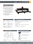
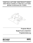
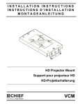
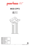
INSTALLATION INSTRUCTIONS
INSTRUCTIONS D'INSTALLATION
MONTAGEANLEITUNG
Low Profile Projector Mounting Kit
Kit de montage peu encombrant pour projecteur
Projektorhalterungsset mit flachem Profil
LPK1
LPK1
Installation Instructions
DISCLAIMER
Milestone AV Technologies and its affiliated corporations and
subsidiaries (collectively "Milestone"), intend to make this
manual accurate and complete. However, Milestone makes no
claim that the information contained herein covers all details,
conditions or variations, nor does it provide for every possible
contingency in connection with the installation or use of this
product. The information contained in this document is subject
to change without notice or obligation of any kind. Milestone
makes no representation of warranty, expressed or implied,
regarding the information contained herein. Milestone assumes
no responsibility for accuracy, completeness or sufficiency of
the information contained in this document.
WARNING: Use this mounting system only for its intended
use as described in these instructions. Do not use
attachments not recommended by the manufacturer.
WARNING: Never operate this mounting system if it is
damaged. Return the mounting system to a service center for
examination and repair.
WARNING: Do not use this product outdoors.
IMPORTANT ! : The LPK1 mount is designed to be:
•
Chief® is a registered trademark of Milestone AV Technologies.
All rights reserved.
•
IMPORTANT SAFETY INSTRUCTIONS
•
WARNING: A WARNING alerts you to the possibility of
serious injury or death if you do not follow the instructions.
•
mounted to double 2" x 4" wood stud cross bracing
between two 2" x 4" ceiling joists; or
mounted to a concrete ceiling with a minimum
thickness of 8" and a maximum drywall covering of
5/8" using 5/16" x 2-1/2" lag bolts (not included) for
Fischer UX8 concrete anchors (not included) or
Toggler AF8 concrete anchors (not included); or
suspended from four 3/8 in. diameter ASTM A307 or
stronger threaded rods (Threaded rods must have 16
threads per inch - not included) which are secured to a
1-5/8" x 1-5/8" 12ga metal framing strut channel
(spanning a maximum of 4 feet--not included) by ASTM
A307 or stronger 3/8" channel nuts (not included).
used with a UL Listed Chief VCM projector mount.
CAUTION: A CAUTION alerts you to the possibility of
damage or destruction of equipment if you do not follow the
corresponding instructions.
WARNING: Failure to read, thoroughly understand, and
follow all instructions can result in serious personal injury,
damage to equipment, or voiding of factory warranty! It is the
installer’s responsibility to make sure all components are
properly assembled and installed using the instructions
provided.
WARNING: Failure to provide adequate structural strength
for this component can result in serious personal injury or
damage to equipment! It is the installer’s responsibility to
make sure the structure to which this component is attached
can support five times the combined weight of all equipment.
Reinforce the structure as required before installing the
component.
WARNING: Exceeding the weight capacity can result in
serious personal injury or damage to equipment! It is the
installer’s responsibility to make sure the combined weight of
all components attached to the LPK1 does not exceed 250 lbs
(113.4 kg).
•
2
The weight capacity of the LPK1 may be LIMITED to
the lowest weight capacity of any other components
located between the VCM and the supporting structure!
--SAVE THESE INSTRUCTIONS--
Installation Instructions
LPK1
LEGEND
Tighten Fastener
Adjust
Apretar elemento de fijación
Ajustar
Befestigungsteil festziehen
Einstellen
Apertar fixador
Ajustar
Serrare il fissaggio
Regolare
Bevestiging vastdraaien
Afstellen
Serrez les fixations
Ajuster
Loosen Fastener
Open-Ended Wrench
Aflojar elemento de fijación
Llave de boca
Befestigungsteil lösen
Gabelschlüssel
Desapertar fixador
Chave de bocas
Allentare il fissaggio
Chiave a punte aperte
Bevestiging losdraaien
Steeksleutel
Desserrez les fixations
Clé à fourche
Hex-Head Wrench
Llave de cabeza hexagonal
Sechskantschlüssel
Chave de cabeça sextavada
Chiave esagonale
Zeskantsleutel
Clé à tête hexagonale
DIMENSIONS
DIMENSIONS: INCHES
[MILLIMETERS]
2X
0.34
8.7
0.56
14.2
15.50
393.7
3
LPK1
Installation Instructions
TOOLS REQUIRED FOR INSTALLATION
7/32" (wood stud)
5/16" (concrete)
PARTS
A (1)
[LPK1 bracket]
4
1/2"
Installation Instructions
LPK1
PREPARATION
INSTALLATION
1.
Remove and SAVE four nuts from top of VCM mount (not
included). (See Figure 1)
The LPK1 mount is designed to be:
2.
Remove and discard top slide plate. (See Figure 1)
•
•
1
x4
•
mounted to double 2" x 4" wood stud cross bracing
between two 2" x 4" ceiling joists;
mounted to a concrete ceiling with a minimum
thickness of 8" and a maximum drywall covering of
5/8" using 5/16" x 2-1/2" lag bolts (not included) for
Fischer UX8 concrete anchors (not included) or
Toggler AF8 concrete anchors (not included); or
suspended from four 3/8 in. diameter ASTM A307 or
stronger threaded rods (not included) which are
secured to a 1-5/8" x 1-5/8" 12ga metal framing strut
channel (spanning a maximum of 4 feet--not included)
by 3/8" channel nuts (not included).
NOTE: Proceed to Wood Stud Installation section, Solid
Concrete Installation section, or Threaded Rod
Installation section.
Wood Installation
Top slide
plate
2
1.
Carefully determine required mounting location.
IMPORTANT ! : This will require knowing the lens to
screen distance. See projector specifications for details
on determining this distance.
WARNING: IMPROPER INSTALLATION CAN RESULT IN
SERIOUS PERSONAL INJURY OR DAMAGE TO
EQUIPMENT! Structural members MUST be capable of
supporting five times the combined weight of all equipment
being mounted.
VCM
Figure 1
IMPORTANT ! : The LPK1 mounts are designed to be
3.
Place LPK1 mount (A) open side up on top of VCM, with
VCM studs fitting through LPK1 slots. (See Figure 2)
mounted to double 2" x 4" wood stud cross bracing between
two ceiling joists.
4.
Tighten LPK1 (A) in place using four nuts removed in Step 1.
(See Figure 2)
2.
Using the LPK1 as a guide, mark four mounting hole
locations. Hole locations must be centered on 2" x 4" cross
braces.
3.
Drill four 7/32" diameter x 1-3/4" long pilot holes.
3
x4
2
3
x4
(A)
2
Figure 2
Figure 3
5
LPK1
4.
Installation Instructions
Align four mounting holes in LPK1 with four pilot holes. (See
Figure 4)
IMPORTANT ! : Make sure mount is properly oriented
towards target before securing to structure.
5.
3
2
Secure LPK1 to structure using four 5/16" flat washers and
four 5/16" x 2-1/2" hex head lag bolts (not included). (See
Figure 4)
x4
Figure 5
IMPORTANT ! : Make sure mount is properly oriented
towards target before securing to structure.
WARNING: Anchors (not provided) must be installed into
structurally sound solid concrete. Installation into hollow
concrete block, mortar, or concrete that exhibits cracking,
spalling, or other defects may result in failure of anchor and
serious personal injury or damage to equipment.
x4
5
5.
Install four Fischer UX8 or Toggler AF8 concrete anchors
(not included) by inserting into pilot holes and pounding in
until flush with mounting surface. (See Figure 6)
6.
Secure LPK1 with attached VCM (not included) to structure
using four 5/16" flat washers (not included) and four
5/16" x 2-1/2" lag bolts (not included). (See Figure 6)
x4
x (4)
5
Figure 4
Solid Concrete Installation
1.
Determine mounting location.
WARNING: The LPK1 is designed to be mounted to a
concrete ceiling with a minimum thickness of 8" and a
maximum drywall covering of 5/8".
WARNING: IMPROPER INSTALLATION CAN RESULT IN
SERIOUS PERSONAL INJURY OR DAMAGE TO
EQUIPMENT! Structural members MUST be capable of
supporting five times the combined weight of all equipment
being mounted.
2.
Using the LPK1 as a guide, mark four mounting hole
locations on ceiling. (See Figure 5)
3.
Drill four 5/16" diameter x 3-1/4" long pilot holes. (See
Figure 5)
4.
Align four mounting holes in LPK1 with four pilot holes.
6
x4
6
Figure 6
x4
Installation Instructions
LPK1
Threaded Rod Installation
INSTALLING PROJECTOR
The LPK1 may be suspended from four 3/8" diameter ASTM
A307 or stronger threaded rods (not included) which are
secured to a 1-5/8" x 1-5/8" 12ga metal framing strut channel
(spanning a maximum of 4 feet--not included) by ASTM A307 or
stronger 3/8" channel nuts (not included).
Install projector with attached interface bracket to VCM (not
included) following instructions included with the VCM.
WARNING: IMPROPER INSTALLATION CAN RESULT IN
SERIOUS PERSONAL INJURY OR DAMAGE TO
EQUIPMENT! Structural members MUST be capable of
supporting five times the combined weight of all equipment
being mounted.
1.
Carefully determine required mount position.
IMPORTANT ! : This will require knowing the lens to
screen distance. See projector specifications for
determining this distance.
2.
Secure one end of the threaded rod to the structural
member.
3.
Install four 3/8" jam nuts and washers on each threaded rod.
4.
Install the LPK1 with VCM (not included) onto the threaded
rod. (See Figure 7)
5.
Secure the LPK1 to the threaded rod using four 3/8"
washers and jam nuts. (See Figure 7)
4
x8
5
x8
Figure 7
7
LPK1
CLAUSES DE NON-RESPONSABILITÉ
Milestone AV Technologies, ainsi que ses filiales et entreprises
affiliées (collectivement « Milestone »), ont fait en sorte que ce
manuel soit exact et exhaustif. Cependant, Milestone ne
garantit pas que les informations contenues dans le présent
document couvrent tous les aspects, conditions ou variations,
et ne peut prévoir tous les événements imprévus liés à
l'installation ou à l'utilisation de ce produit. Les informations
mentionnées au présent document sont susceptibles d'être
modifiées sans aucun préavis ni obligation d'aucune sorte.
Milestone ne consent aucune garantie, expresse ou implicite,
au titre des informations contenues dans le présent document.
Milestone ne garantit pas que les informations mentionnées au
présent document sont exactes, exhaustives et suffisantes.
Installation Instructions
•
La capacité pondérale du LPK1 peut être LIMITÉE à la
capacité pondérale la plus basse de tout autre
composant situé entre le VCM et la structure support !
AVERTISSEMENT : N'utilisez ce système de montage que
pour l'usage prévu conformément à ces directives. N'utilisez
pas d'accessoires non recommandés par le fabricant.
AVERTISSEMENT : N'utilisez en aucun cas ce système
de montage s'il est endommagé. Dans ce cas, renvoyez le
système à un centre d'entretien pour examen et réparation.
AVERTISSEMENT : N'utilisez pas ce produit à l'extérieur.
Chief® est une marque déposée de Milestone AV
Technologies. Tous droits réservés.
IMPORTANT ! Le système de montage LPK1 est conçu
pour être :
•
DIRECTIVES DE SÉCURITÉ
IMPORTANTES
•
AVERTISSEMENT : Un AVERTISSEMENT indique un
risque potentiel de blessure grave ou de décès en cas de
non-respect des instructions.
•
MISE EN GARDE : Une MISE EN GARDE indique un
risque potentiel de dommage ou de destruction de
l'équipement en cas de non-respect des instructions
correspondantes.
•
monté sur des doubles contreventements transversaux
de montants en bois de 51 mm x 102 mm (2" x 4") entre
deux solives de plafond de 51 mm x 102 mm (2" x 4"),
ou
monté sur un plafond en béton d'une épaisseur
minimale de 203 mm (8") et un revêtement de cloison
sèche d'épaisseur maximale de 16 mm (5/8") au
moyen de boulons tire-fond de 5/16" x 2-1/2" (non
fournis) pour dispositifs d'ancrage pour béton Fischer
UX8 (non fournis) ou Toggler AF8 (non fournis), ou
suspendu à l'aide de quatre tiges filetées (non fournies)
de 9,5 mm (3/8") de diamètre de calibre ASTM A307 ou
supérieur (les tiges filetées doivent avoir 16 filets au
pouce), arrimées à un profilé métallique de calibre 12
de 1-5/8" x 1-5/8" (d'une longueur maximale de 122
cm, non fourni) par des écrous crénelés de 3/8" (non
fournis) de calibre ASTM A307 ou supérieur.
utilisé avec un système de montage pour projecteur
Chief VCM homologué UL.
AVERTISSEMENT : Le fait de ne pas lire, de ne pas bien
comprendre et de ne pas suivre toutes les instructions peut
entraîner de graves blessures corporelles, endommager
l'équipement ou annuler la garantie du fabricant ! Il est de la
responsabilité de l'installateur de s'assurer que tous les
composants sont correctement assemblés et installés
conformément aux instructions fournies.
AVERTISSEMENT : Une résistance structurale
inadéquate pour ce composant peut entraîner de graves
blessures corporelles ou endommager l'équipement ! Il est
de la responsabilité de l'installateur de s'assurer que la
structure à laquelle ce composant est attaché peut supporter
cinq fois le poids total de l'équipement. Si nécessaire,
renforcez la structure avant d'installer le composant.
AVERTISSEMENT : Le dépassement des limites de
poids peut entraîner de graves blessures corporelles ou
endommager l'équipement ! Il est de la responsabilité de
l'installateur de s'assurer que le poids total de tous les
composants attachés au LPK1 ne dépasse pas 113,4 kg
(250 lbs).
8
--CONSERVEZ CES INSTRUCTIONS--
Installation Instructions
LPK1
DIMENSIONS
DIMENSIONS : POUCES
[MILLIMÈTRES]
2X
0.34
8.7
0.56
14.2
15.50
393.7
OUTILS NÉCESSAIRES À L'INSTALLATION
5,5 mm (7/32") (montant en bois)
8 mm (5/16") (béton)
12,7 mm (1/2")
PIÈCES
A (1)
[patte de fixation LPK1]
9
LPK1
Installation Instructions
PRÉPARATION
INSTALLATION
1.
Le système de montage LPK1 est conçu pour être :
Retirez et CONSERVEZ les quatre écrous sur la partie
supérieure du système de montage VCM (non fourni).
(voir la Figure 1)
2.
•
Retirez et mettez de côté la plaque coulissante supérieure.
(voir la Figure 1)
1
•
x4
•
monté sur des doubles contreventements transversaux
de montants en bois de 51 mm x 102 mm (2" x 4") entre
deux solives de plafond de 51 mm x 102 mm (2" x 4"),
monté sur un plafond en béton d'une épaisseur
minimale de 203 mm (8") et un revêtement de cloison
sèche d'épaisseur maximale de 16 mm (5/8") au
moyen de boulons tire-fond de 5/16" x 2-1/2" (non
fournis) pour dispositifs d'ancrage pour béton Fischer
UX8 (non fournis) ou Toggler AF8 (non fournis), ou
suspendu à l'aide de quatre tiges filetées (non fournies)
de 9,5 mm (3/8") de diamètre de calibre ASTM A307 ou
supérieur, arrimées à un profilé métallique de calibre
12 de 1-5/8" x 1-5/8" (d'une longueur maximale de
122 cm, non fourni) par des écrous crénelés de 3/8"
(non fournis).
REMARQUE : Passez à la section Installation sur des
Plaque
coulissante
supérieure
montants en bois, Installation sur du béton
solide ou Installation à l'aide de tiges filetées.
Installation sur des montants en bois
1.
Déterminez soigneusement l'emplacement de montage requis.
IMPORTANT ! Cela nécessite de connaître la distance entre la
2
lentille et l'écran. Pour vous aider à déterminer cette distance,
consultez les caractéristiques techniques du projecteur.
AVERTISSEMENT : UNE INSTALLATION INCORRECTE
PEUT ENTRAÎNER DE GRAVES BLESSURES OU
ENDOMMAGER L'ÉQUIPEMENT ! Les pièces de charpente
DOIVENT être capables de supporter cinq fois le poids total
de l'équipement monté.
VCM
Figure 1
3.
Placez le système de montage LPK1 (A) ouvert côté orienté
vers le haut sur la partie supérieure du VCM, en insérant les
montants du VCM dans les fentes du LPK1. (voir la Figure 2)
4.
Serrez le LPK1 (A) à l'aide des quatre écrous retirés à
l'étape 1. (voir la Figure 2)
3
IMPORTANT ! Les systèmes de montage LPK1 sont conçus
pour être montés sur des doubles contreventements transversaux
de montants en bois de 51 mm x 102 mm (2" x 4") entre deux
solives de plafond.
2.
En vous servant du LPK1 comme guide, marquez quatre
emplacements pour les trous de montage. Les emplacements
des trous doivent être centrés sur des contreventements
transversaux de 51 mm x 102 mm (2" x 4").
3.
Percez quatre avant-trous de 5,6 mm (7/32") de diamètre et
de 44,5 mm (1-3/4") de long.
x4
2
3
x4
(A)
2
Figure 2
10
Figure 3
Installation Instructions
4.
LPK1
Alignez les quatre trous de montage dans le LPK1 sur les
quatre avant-trous. (voir la Figure 4)
IMPORTANT ! Assurez-vous que le système de montage
3
2
est correctement orienté vers la cible avant de le fixer sur la
structure.
x4
5.
Fixez le LPK1 sur la structure à l'aide de quatre rondelles
plates de 5/16" et de quatre boulons tire-fond à tête
hexagonale de 5/16" x 2-1/2" (non fournis). (voir la Figure 4)
Figure 5
IMPORTANT ! Assurez-vous que le système de montage
est correctement orienté vers la cible avant de le fixer sur la
structure.
AVERTISSEMENT : Des dispositifs d'ancrage (non
fournis) doivent être installés dans du béton solide
structurellement stable. Toute installation dans un bloc de
béton creux, du mortier ou du béton présentant des fissures,
des effritements ou d'autres défauts peut causer la
défaillance des dispositifs d'ancrage et entraîner de graves
blessures corporelles ou endommager l'équipement.
x4
5
x4
Figure 4
5.
Installez quatre dispositifs d'ancrage pour béton Fischer
UX8 ou Toggler AF8 (non fournis) en les insérant dans les
avant-trous et en les enfonçant jusqu'à ce qu'ils affleurent à
la surface de montage. (voir la Figure 6)
6.
Fixez le LPK1 avec le VCM attaché (non fourni) sur la
structure à l'aide de quatre rondelles plates de 5/16" (non
fournies) et de quatre boulons tire-fond de 5/16" x 2-1/2"
(non fournis). (voir la Figure 6)
Installation sur du béton solide
1.
Déterminez l'emplacement de montage.
x (4)
5
AVERTISSEMENT : Le LPK1 est conçu pour être monté
sur un plafond en béton d'une épaisseur minimale de
203 mm et un revêtement de cloison sèche d'épaisseur
maximale de 16 mm (5/8").
AVERTISSEMENT : UNE INSTALLATION INCORRECTE
PEUT ENTRAÎNER DE GRAVES BLESSURES OU
ENDOMMAGER L'ÉQUIPEMENT ! Les pièces de charpente
DOIVENT être capables de supporter cinq fois le poids total
de l'équipement monté.
2.
En vous servant du LPK1 comme guide, marquez quatre
emplacements pour les trous de montage sur le plafond.
(voir la Figure 5)
3.
Percez quatre avant-trous de 7,9 mm (5/16") de diamètre et
de 82,6 mm (3-1/4") de long. (voir la Figure 5)
4.
Alignez les quatre trous de montage dans le LPK1 sur les
quatre avant-trous.
x4
6
x4
Figure 6
11
LPK1
Installation Instructions
Installation à l'aide de tiges filetées
INSTALLATION DU PROJECTEUR
Le LPK1 peut être suspendu à l'aide de quatre tiges filetées
(non fournies) de 9,5 mm (3/8") de diamètre de calibre ASTM
A307 ou supérieur, arrimées à un profilé métallique de calibre
12 de 1-5/8" x 1-5/8" (d'une longueur maximale de 122 cm,
non fourni) par des écrous crénelés de 3/8" (non fournis) de
calibre ASTM A307 ou supérieur.
Installez le projecteur avec la patte de fixation d'interface
attachée au VCM (non fourni) en suivant les instructions
fournies avec le VCM.
AVERTISSEMENT : UNE INSTALLATION INCORRECTE
PEUT ENTRAÎNER DE GRAVES BLESSURES OU
ENDOMMAGER L'ÉQUIPEMENT ! Les pièces de charpente
DOIVENT être capables de supporter cinq fois le poids total
de l'équipement monté.
1.
Déterminez soigneusement l'emplacement de montage requis.
IMPORTANT ! Cela nécessite de connaître la distance entre la
lentille et l'écran. Pour vous aider à déterminer cette distance,
consultez les caractéristiques techniques du projecteur.
2.
Arrimez une extrémité de la tige filetée sur la pièce de
charpente.
3.
Installez quatre contre-écrous de 3/8" sur chaque tige filetée.
4.
Installez le LPK1 avec le VCM (non fourni) sur la tige filetée.
(voir la Figure 7)
5.
Arrimez le LPK1 sur la tige filetée à l'aide de quatre
rondelles et contre-écrous de 3/8". (voir la Figure 7)
4
x8
5
x8
Figure 7
12
Installation Instructions
LPK1
HAFTUNGSAUSSCHLUSS
Milestone AV Technologies sowie seine konzerneigenen
Unternehmen und Tochtergesellschaften (zusammen
"Milestone") haben versucht, dieses Handbuch so genau und
vollständig als möglich zu gestalten. Milestone erhebt jedoch
weder Anspruch auf Vollständigkeit der Einzelheiten,
Bedingungen und Änderungen der hierin enthaltenen
Informationen, noch übernimmt das Unternehmen irgendeine
Haftung für eventuelle Schadensfälle in Verbindung mit der
Installation oder Verwendung dieses Produkts. Die in diesem
Dokument enthaltenen Informationen können ohne vorherige
Ankündigung oder sonstige Verpflichtungen jederzeit geändert
werden. Milestone schließt jegliche ausdrückliche oder
stillschweigende Zusicherung und Gewährleistung bezüglich
der hierin enthaltenen Informationen aus. Milestone übernimmt
keinerlei Verantwortung für die Genauigkeit, Vollständigkeit
oder Angemessenheit der in diesem Dokument enthaltenen
Informationen.
WARNUNG: Verwenden Sie das Halterungssystem nur für
den vorgesehenen, in der Anleitung beschriebenen Zweck.
Verwenden Sie keine Zubehörteile, die nicht vom Hersteller
empfohlen wurden.
WARNUNG: Verwenden Sie das Halterungssystem nie in
beschädigtem Zustand. Bringen Sie das Halterungssystem in
diesem Fall für die Fehlersuche und Reparatur zu einem
Service-Center.
WARNUNG: Verwenden Sie das Produkt nie im Freien.
WICHTIG! Die LPK1-Halterung eignet sich für:
•
•
Chief® ist eine eingetragene Marke von Milestone AV
Technologies. Alle Rechte vorbehalten.
WICHTIGE SICHERHEITSHINWEISE
•
WARNUNG: WARNUNG weist darauf hin, dass bei
Nichtbefolgung der Anweisungen Verletzungs- oder
Lebensgefahr besteht.
VORSICHT: VORSICHT weist darauf hin, dass bei
•
die Montage an einer doppelten Querverstrebung aus
51 mm x 102 mm (2" x 4")-Holzbalken zwischen zwei
51 mm x 102 mm (2" x 4") Deckenbalken; oder
die Montage an eine Betondecke mit einer Mindeststärke
von 203 mm (8") und einer Gipskartonbeschichtung von
maximal 16 mm (5/8") mithilfe von (nicht mitgelieferten)
5/16" x 2-1/2"-Ankerschrauben für Fischer-UX8Betondübel (nicht mitgeliefert) oder Toggler-AF8Betondübel (nicht mitgeliefert); oder
die Aufhängung an vier ASTM A307-Gewindestangen
mit einem Durchmesser von 9,5 mm (3/8") oder stärker
(Gewindestangen müssen über 16 Gänge pro Zoll
verfügen – nicht mitgeliefert), die mittels (nicht
mitgelieferter) ASTM A307-3/8"-Rechteckmuttern (oder
stärker – nicht mitgeliefert) an einer 1-5/8" x 1-5/8" 12ga
Metallschiene (mit einer Höchstlänge von 122 cm / 4
Fuß – ebenfalls nicht mitgeliefert) befestigt werden.
die Verwendung in Kombination mit einer ULkonformen VCM-Projektorhalterung von Chief.
Nichtbefolgung der Anweisungen die Möglichkeit von
Geräteschäden besteht.
--BEWAHREN SIE DIESE ANWEISUNGEN AUF-WARNUNG: Die Nichtbefolgung dieser Anweisungen kann
zu schweren Verletzungen und Geräteschäden sowie zum
Erlöschen der Garantie führen. Der Monteur hat dafür zu
sorgen, dass alle Bauelemente nach den beiliegenden
Anweisungen montiert und installiert werden.
WARNUNG: Wenn dieses Bauelement nicht an einer
Konstruktion mit der erforderlichen Tragfähigkeit montiert
wird, kann dies zu schweren Verletzungen oder
Geräteschäden führen! Der Monteur hat dafür zu sorgen,
dass die Konstruktion, an der das Bauelement angebracht
wird, über die erforderliche Tragfähigkeit verfügt.
Die Konstruktion muss das fünffache Gesamtgewicht des
Geräts tragen können. Verstärken Sie vor der Montage des
Bauelements ggf. die Konstruktion.
WARNUNG: Das Überschreiten der maximalen Tragkraft
kann zu schweren Verletzungen oder Geräteschäden führen!
Der Monteur ist dafür verantwortlich, sicherzustellen, dass
das Gesamtgewicht aller Komponenten, die mit dem LPK1
verbunden sind, 113,4 kg (250 lbs) nicht überschreitet.
•
Die maximale Tragkraft des LPK1 ist auf die maximale
Tragkraft des zwischen der VCM und der tragenden
Konstruktion verwendeten sonstigen Bauelements mit
der jeweils niedrigsten Tragkraft BESCHRÄNKT!
13
LPK1
Installation Instructions
ABMESSUNGEN
ABMESSUNGEN: ZOLL
[MILLIMETER]
2X
0.34
8.7
0.56
14.2
15.50
393.7
FÜR DIE MONTAGE ERFORDERLICHES WERKZEUG
5,5 mm (7/32") (Holzbalken)
8 mm (5/16") (Beton)
TEILE
A (1)
[LPK1-Anschlussplatte]
14
12,7 mm (1/2")
Installation Instructions
LPK1
VORBEREITUNG
MONTAGE
1.
Die LPK1-Halterung eignet sich für:
2.
Entfernen Sie die vier Muttern von der Oberseite der
(nicht mitgelieferten) VCM-Halterung und BEWAHREN Sie
sie AUF. (Siehe Abb. 1)
•
Entfernen Sie die obere, verschiebbare Platte, sie ist nun
überflüssig. (Siehe Abb. 1)
1
•
x4
•
die Montage an einer doppelten Querverstrebung aus
51 mm x 102 mm (2" x 4")-Holzbalken zwischen zwei
51 mm x 102 mm (2" x 4") Deckenbalken;
die Montage an eine Betondecke mit einer Mindeststärke
von 203 mm (8") und einer Gipskartonbeschichtung von
maximal 16 mm (5/8") mithilfe von (nicht mitgelieferten) 5/
16" x 2-1/2"-Ankerschrauben für Fischer-UX8-Betondübel
(nicht mitgeliefert) oder Toggler-AF8-Betondübel (nicht
mitgeliefert); oder
die Aufhängung an vier ASTM A307-Gewindestangen
mit einem Durchmesser von 9,5 mm (3/8") oder stärker
(nicht mitgeliefert), die mittels (nicht mitgelieferter)
3/8"-Rechteckmuttern an einer 1-5/8" x 1-5/8" 12ga
Metallschiene (mit einer Höchstlänge von 122 cm /
4 Fuß – ebenfalls nicht mitgeliefert) befestigt werden.
HINWEIS: Fahren Sie beim Abschnitt Montage an Holzbalken,
Obere,
verschibare
Platte
beim Abschnitt Montage an Massivbeton oder beim
Abschnitt Montage an Gewindestangen fort.
Montage an Holzbalken
1.
2
Wählen Sie sorgfältig eine Montagestelle aus.
WICHTIG! Hierzu müssen Sie den Abstand zwischen
Linse und Leinwand kennen. Die technischen Daten des
Projektors bieten Ihnen Informationen zur Bestimmung
dieses Abstands.
VCM
WARNUNG: EINE UNSACHGEMÄSSE MONTAGE
Abb. 1
3.
Platzieren Sie die LPK1-Halterung (A) mit der offenen Seite
nach oben auf der VCM, wobei Sie die VCM-Stifte durch die
LPK1-Schlitze schieben. (Siehe Abb. 2)
4.
Fixieren Sie das LPK1 (A) mit den in Schritt 1 entfernten vier
Muttern. (Siehe Abb. 2)
3
x4
KANN ZU SCHWEREN VERLETZUNGEN ODER
GERÄTESCHÄDEN FÜHREN! Die Bauteile MÜSSEN das
fünffache Gesamtgewicht des montierten Geräts tragen können.
WICHTIG! LPK1-Halterungen eignen sich für die Montage an
einer doppelten Querverstrebung aus 51 mm x
102 mm (2" x 4")-Holzbalken zwischen zwei Deckenbalken.
2.
3.
Zeichnen Sie mithilfe des LPK1 als Schablone vier Bohrstellen
an. Die Bohrstellen müssen jeweils in der Mitte zweier 51 mm x
102 mm (2" x 4")-Querstreben angebracht werden.
Bohren Sie vier Vorbohrungen mit einem Durchmesser von
5,6 mm (7/32") und einer Tiefe von 44,5 mm (1-3/4").
2
3
x4
(A)
2
Abb. 2
Abb. 3
15
LPK1
4.
Installation Instructions
Richten Sie die vier Montagebohrungen im LPK1 nach den
vier Vorbohrungen aus. (Siehe Abb. 4)
WICHTIG! Stellen Sie sicher, dass die Halterung genau
auf das Ziel gerichtet ist, bevor Sie sie an der
Konstruktion befestigen.
5.
3
2
x4
Befestigen Sie das LPK1 mit vier 5/16"-Unterlegscheiben
und vier 5/16" x 2-1/2"-Sechskantankerschrauben
(nicht mitgeliefert) an der Konstruktion. (Siehe Abb. 4)
Abb. 5
WICHTIG! Stellen Sie sicher, dass die Halterung genau
auf das Ziel gerichtet ist, bevor Sie sie an der
Konstruktion befestigen.
WARNUNG: Dübel (nicht mitgeliefert) müssen in baulich
intakte Massivbetondecken montiert werden. Die Installation
in Hohlblockdecken, Mörtel oder Beton, der Risse,
Absplitterungen oder andere Defekte aufweist, kann zu
einem Versagen des Dübels und schweren Personen- oder
Sachschäden führen.
x4
5.
6.
5
x4
Stecken Sie vier (nicht mitgelieferte) Fischer-UX8- oder
Toggler-AF8-Betondübel in die Vorbohrungen und schlagen
Sie sie mit dem Hammer ein, bis sie bündig mit der
Befestigungsfläche abschließen. (Siehe Abb. 6)
Befestigen Sie das LPK1 mit der daran befestigten (nicht
mitgelieferten) VCM mithilfe von vier (nicht mitgelieferten) 5/
16"-Unterlegscheiben und vier (nicht mitgelieferten) 5/16" x
2-1/2"-Ankerschrauben an der Konstruktion. (Siehe Abb. 6)
Abb. 4
1.
x (4)
5
Montage an Massivbeton
Wählen Sie eine Montagestelle aus.
WARNUNG: Das LPK1 eignet sich zur Montage an einer
Betondecke mit einer Mindeststärke von 203 mm (8") und
einer Gipskartonbeschichtung von maximal 16 mm (5/8").
WARNUNG: EINE UNSACHGEMÄSSE MONTAGE
KANN ZU SCHWEREN VERLETZUNGEN ODER
GERÄTESCHÄDEN FÜHREN! Die Bauteile MÜSSEN
das fünffache Gesamtgewicht des montierten Geräts
tragen können.
2.
Zeichnen Sie mithilfe des LPK1 als Schablone vier
Bohrstellen an die Decke. (Siehe Abb. 5)
3.
Bohren Sie vier Vorbohrungen mit einem Durchmesser
von 7,9 mm (5/16") und einer Tiefe von 82,6 mm (3-1/4").
(Siehe Abb. 5)
4.
Richten Sie die vier Montagebohrungen im LPK1 nach den
vier Vorbohrungen aus.
16
x4
6
Abb. 6
x4
Installation Instructions
LPK1
Montage an Gewindestangen
MONTAGE DES PROJEKTORS
Das LPK1 kann an vier ASTM A307-Gewindestangen mit einem
Durchmesser von 9,5 mm (3/8") oder stärker (nicht mitgeliefert)
aufgehängt werden, die mittels (nicht mitgelieferter) ASTM A307
3/8"-Rechteckmuttern (oder stärker) an einer 1-5/8" x 1-5/8" 12ga
Metallschiene (mit einer Höchstlänge von 122 cm / 4 Fuß –
ebenfalls nicht mitgeliefert) befestigt werden.
Montieren Sie den Projektor mit der daran befestigten
Anschlussplatte gemäß der der VCM beiliegenden Anleitung an
die (nicht mitgelieferte) VCM.
WARNUNG: EINE UNSACHGEMÄSSE MONTAGE
KANN ZU SCHWEREN VERLETZUNGEN ODER
GERÄTESCHÄDEN FÜHREN! Die Bauteile MÜSSEN das
fünffache Gesamtgewicht des montierten Geräts tragen können.
1.
Wählen Sie sorgfältig eine Montagestelle aus.
WICHTIG! Hierzu müssen Sie den Abstand zwischen
Linse und Leinwand kennen. Die technischen Daten des
Projektors bieten Ihnen Informationen zur Bestimmung
dieses Abstands.
2.
Befestigen Sie ein Ende der Gewindestange am Bauteil.
3.
Montieren Sie vier 3/8"-Kontermuttern und
Unterlegscheiben an den Gewindestangen.
4.
Montieren Sie das LPK1 samt der (nicht mitgelieferten)
VCM an den Gewindestangen. (Siehe Abb. 7)
5.
Befestigen Sie das LPK1 mit vier 3/8"-Unterlegscheiben
und Kontermuttern an den Gewindestangen. (Siehe Abb. 7)
4
x8
5
x8
Abb. 7
17
LPK1
18
Installation Instructions
Installation Instructions
LPK1
19
LPK1
Installation Instructions
USA/International
Europe
Chief Manufacturing, a products division
of Milestone AV Technologies
8800-002410 Rev00
2013 Milestone AV Technologies, a
Duchossois Group Company
www.chiefmfg.com
05/13
Asia Pacific
A
P
F
A
P
F
A
6436 City West Parkway, Eden Prairie, MN 55344
800.582.6480 / 952.225.6000
877.894.6918 / 952.894.6918
Franklinstraat 14, 6003 DK Weert, Netherlands
+31 (0) 495 580 852
+31 (0) 495 580 845
Office No. 1 on 12/F, Shatin Galleria
18-24 Shan Mei Street
Fotan, Shatin, Hong Kong
P 852 2145 4099
F 852 2145 4477