1
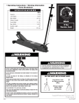
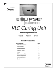
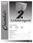
INSTALLATION INSTRUCTIONS
INSTRUCTIONS D'INSTALLATION
MONTAGEANLEITUNG
Universal HB Interface
Interface universelle HB
HB-Universalanschlussplatte
HBU
HBU
Installation Instructions
DISCLAIMER
Milestone AV Technologies and its affiliated corporations and
subsidiaries (collectively "Milestone"), intend to make this
manual accurate and complete. However, Milestone makes no
claim that the information contained herein covers all details,
conditions or variations, nor does it provide for every possible
contingency in connection with the installation or use of this
product. The information contained in this document is subject
to change without notice or obligation of any kind. Milestone
makes no representation of warranty, expressed or implied,
regarding the information contained herein. Milestone assumes
no responsibility for accuracy, completeness or sufficiency of
the information contained in this document.
WARNING: Never operate this mounting system if it is
damaged. Return the mounting system to a service center for
examination and repair.
WARNING: Do not use this product outdoors.
IMPORTANT ! : These instructions assume that an
appropriate mounting method (not included) has already been
properly installed to a ceiling structure.
--SAVE THESE INSTRUCTIONS-Chief® is a registered trademark of Milestone AV Technologies.
All rights reserved.
IMPORTANT SAFETY INSTRUCTIONS
WARNING: A WARNING alerts you to the possibility of
serious injury or death if you do not follow the instructions.
CAUTION: A CAUTION alerts you to the possibility of
damage or destruction of equipment if you do not follow the
corresponding instructions.
WARNING: Failure to read, thoroughly understand, and
follow all instructions can result in serious personal injury,
damage to equipment, or voiding of factory warranty! It is the
installer’s responsibility to make sure all components are
properly assembled and installed using the instructions
provided.
WARNING: Failure to provide adequate structural strength
for this component can result in serious personal injury or
damage to equipment! It is the installer’s responsibility to
make sure the structure to which this component is attached
can support five times the combined weight of all equipment.
Reinforce the structure as required before installing the
component.
WARNING: Exceeding the weight capacity can result in
serious personal injury or damage to equipment! It is the
installer’s responsibility to make sure the weight of the
projector attached to the HBU interface bracket does not
exceed 250 lbs (113.4 kg).
WARNING: Use this mounting system only for its intended
use as described in these instructions. Do not use
attachments not recommended by the manufacturer.
2
Installation Instructions
HBU
DIMENSIONS
665.7
26.21
MAX DEPTH
745.1
29.33
MAX WIDTH
.50
INCLUDES M4, M5,
M6, M8, M10, AND
M12 SCREWS
36
1.42
MINIMUM
HEIGHT
51.9
2.04
MAXIMUM
HEIGHT
DIMENSIONS: [MILLIMETERS]
INCHES
LEGEND
Tighten Fastener
Adjust
Apretar elemento de fijación
Ajustar
Befestigungsteil festziehen
Einstellen
Apertar fixador
Ajustar
Serrare il fissaggio
Regolare
Bevestiging vastdraaien
Afstellen
Serrez les fixations
Ajuster
Loosen Fastener
Open-Ended Wrench
Aflojar elemento de fijación
Llave de boca
Befestigungsteil lösen
Gabelschlüssel
Desapertar fixador
Chave de bocas
Allentare il fissaggio
Chiave a punte aperte
Bevestiging losdraaien
Steeksleutel
Desserrez les fixations
Clé à fourche
Phillips Screwdriver
Hex-Head Wrench
Destornillador Phillips
Llave de cabeza hexagonal
Kreuzschlitzschraubendreher
Sechskantschlüssel
Chave de fendas Phillips
Chave de cabeça sextavada
Cacciavite a stella
Chiave esagonale
Kruiskopschroevendraaier
Zeskantsleutel
Tournevis à pointe cruciforme
Clé à tête hexagonale
3
HBU
Installation Instructions
TOOLS REQUIRED FOR INSTALLATION
1/2"
PARTS
BAG A
A (8)
M5 x 20mm
BAG B
BAG C
BA (8)
M6 x 16mm
CA (8)
M8 x 12mm
CB (8)
M8 x 16mm
BB (8)
M6 x 25mm
D (8)
M10 x 20mm
BAG D
E (8)
M12 x 20mm
BAG E
FA (8)
5/16"
FB (8)
5/16"
BAG F
CC (8)
M8
JA (8)
M4x16mm
G (8)
[Nesting washer]
BAG G
H (4)
5/16"
BAG H
JB (8)
M5
BAG J
L (8)
[HBU leg]
K (1)
[HB plate]
4
Installation Instructions
HBU
INSTALLATION
WARNING: FAILURE TO PROVIDE ADEQUATE
[Example
using nesting 2
washers (G)]
(A, BA, BB or JA)
x number of legs (L)
STRUCTURAL STRENGTH FOR THIS COMPONENT CAN
RESULT IN SERIOUS PERSONAL INJURY OR DAMAGE
TO EQUIPMENT! It is the installer’s responsibility to make
sure the structure to which this component is attached can
support five times the combined weight of all equipment.
Reinforce the structure as required before installing the
component.
(G)
(JB) with (JA) only
(L)
Installing VCM Ceiling Mount
Install the VCM ceiling mount (not included) to the structure
following instructions included with the VCM mount.
Installing HBU Bracket
WARNING: IMPROPER INSTALLATION CAN LEAD TO
PROJECTOR FALLING CAUSING SERIOUS PERSONAL
INJURY OR DAMAGE TO EQUIPMENT! Using screws of
improper size may damage your projector. Properly sized
screws will easily and completely thread into projector
mounting holes.
1.
Projector
Select correct screws and washers from the hardware bags
(A, B, C, D, E, G, J). (See Table 1)
Nesting washer
in place
Table 1
Fastener Size
Washer
M4x16mm (JA)
M4 washer (JB), Nesting Washer (G)
M5x20mm (A)
Nesting Washer (G)
M6x16mm (BA)
Nesting Washer (G)
M6x25mm (BB)
Nesting Washer (G)
Figure 1
[Example
using M8 flat
washers (CC)]
2
(CA or CB) x number of legs (L)
(CC)
M8x12mm (CA)
M8 washer (CC)
M8x16mm (CB)M8
M8 washer (CC)
M10x20mm (D)
No washer
M12x20mm (E)
No washer
2.
(L)
Attach HBU legs (L) to projector using selected fasteners
and washers. (See Figure 1) and (See Figure 2)
WARNING: One HBU leg should be attached to each
available mounting hole in the projector. A minimum of three
legs must be used if using M5 or larger fasteners. A minimum
of four legs must be used if using M4 fasteners.
Projector
Figure 2
5
HBU
3.
Installation Instructions
Lower HB plate (K) onto legs and fasten using one 5/16"
lock nut (FA) and one 5/16" flat washer (FB) on each HBU
leg (L). (See Figure 3)
Seat VCM in HBU
bracket slots
(FB)
2
(FA) x number
of legs
VCM
mount
(K)
1
(L)
Projector
2
(H) x 4
Figure 3
Installing HBU Bracket to VCM
Figure 4
2.
CAUTION: Installing a ceiling mount requires the presence
of two persons familiar with mechanical installations. A third
assistant is recommended.
1.
With help of assistants, lift the HBU bracket with the
attached projector and install it to the four studs extending
from the VCM ceiling mount (not included). (See Figure 4)
IMPORTANT ! : Ensure that the VCM ceiling mount is
seated in slots on HBU bracket. (See Figure 4)
Fasten with four 5/16" flange nuts (H). (See Figure 4)
IMPORTANT ! : Ensure that four flange nuts are
tightened securely.
Adjustments
WARNING: MOUNTING HARDWARE IS TO BE
LOOSENED ONLY ENOUGH TO ALLOW FOR
NECESSARY MOVEMENT. Over-loosening or removal of
mounting hardware may result in personal injury or serious
damage to equipment!
Adjustments should be made following instructions
accompanying the VCM ceiling mount.
6
Installation Instructions
HBU
CLAUSES DE NON-RESPONSABILITÉ
Milestone AV Technologies, ses filiales et entreprises affiliées
(« Milestone ») ont fait en sorte que ce manuel soit exact et
exhaustif. Cependant, Milestone ne garantit pas que les
informations mentionnées au présent document couvrent tous
les aspects, conditions ou variations dans le détail ; pas plus
qu'elle ne fournit de solution pour chaque imprévu lié au type
d'installation ou d'utilisation de ce produit. Les informations
mentionnées au présent document sont susceptibles d'être
modifiées sans aucun préavis ni obligation. Milestone ne consent
aucune garantie, expresse ou implicite, au titre des informations
contenues dans le présent document. Milestone ne garantit pas
que les informations mentionnées au présent document soient
exactes, exhaustives et suffisantes.
Chief® est une marque déposée de Milestone AV Technologies.
Tous droits réservés.
AVERTISSEMENT : N'utiliser ce système de montage que
pour l'usage prévu conformément à ces directives. Ne pas
utiliser d'accessoires non recommandés par le fabricant.
AVERTISSEMENT : Ne jamais faire fonctionner ce système
de montage s'il est endommagé. Dans ce cas, renvoyer le
système à un service technique pour examen et réparation.
AVERTISSEMENT : Ne pas utiliser ce produit à l'extérieur.
IMPORTANT ! : Ces instructions supposent qu'une méthode
de fixation appropriée (non incluse) a déjà été correctement
installée sur une structure de plafond.
--RANGER CES CONSIGNES EN LIEU SÛR-DIRECTIVES DE SÉCURITÉ IMPORTANTES
AVERTISSEMENT : Un AVERTISSEMENT vous indique
qu'il existe un risque de blessures graves ou de décès si vous
ne suivez pas les instructions.
MISE EN GARDE : Une MISE EN GARDE vous indique qu'il
existe un risque de dommages ou de destruction du matériel si
vous ne suivez pas les instructions correspondantes.
AVERTISSEMENT : Le fait de ne pas lire, de ne pas
comprendre et de ne pas suivre toutes les instructions peut
entraîner des blessures corporelles graves, endommager
l'équipement ou annuler la garantie du fabricant ! Il est de la
responsabilité de l'installateur de s'assurer que tous les
composants sont correctement montés et installés
conformément aux instructions fournies.
AVERTISSEMENT : Une résistance structurelle non
appropriée pour ce composant peut entraîner des blessures
corporelles graves ou endommager l'équipement ! Il est de la
responsabilité de l'installateur de s'assurer que la structure à
laquelle ce composant est attaché peut supporter cinq fois le
poids total de l'équipement. Si nécessaire, renforcez la structure
avant d'installer cet élément.
AVERTISSEMENT : Le dépassement de capacité de poids
peut causer de graves blessures corporelles ou endommager le
matériel ! Il est de la responsabilité de l'installateur de s'assurer
que le poids du projecteur fixé à la patte de fixation d'interface
HBU ne dépasse pas 113,4 kg (250 lbs).
7
HBU
Installation Instructions
DIMENSIONS
DIMENSIONS : [MILLIMÈTRES]
POUCES
OUTILS NÉCESSAIRES À L'INSTALLATION / PIÈCES
SACHET A
A (8)
M5 x 20 mm
SACHET C
SACHET B
BA (8)
M6 x 16 mm
CA (8)
M8 x 12 mm
CC (8)
M8
CB (8)
M8 x 16mm
BB (8)
M6 x 25mm
12,7 mm (1/2")
D (8)
M10 x 20 mm
SACHET D
E (8)
M12 x 20 mm
SACHET E
FA (8)
5/16"
FB (8)
5/16"
SACHET F
G (8)
[Rondelle
d'emboîtement]
H (4)
5/16"
SACHET
SACHET G
H
JA (8)
M4 x 16 mm
JB (8)
M5
SACHET J
L (8)
[Pied HBU]
K (1)
[Plaque HB]
8
Installation Instructions
HBU
INSTALLATION
AVERTISSEMENT : NE PAS FOURNIR UN SUPPORT
STRUCTUREL ADÉQUAT POUR CE COMPOSANT
POURRAIT PROVOQUER DES BLESSURES OU
ENDOMMAGER L'ÉQUIPEMENT ! Il est de la responsabilité de
l'installateur de s'assurer que la structure à laquelle ce
composant est attaché peut supporter cinq fois le poids total de
l'équipement. Si nécessaire, renforcez la structure avant
d'installer cet élément.
[Exemple
2
en utilisant
des rondelles
d'emboîtement]
(A, BA, BB ou JA)
x nombre de pieds (L)
(G)
(JB) avec (JA)
uniquement
(L)
Installation du support de plafond VCM
Installez le support de plafond VCM (non inclus) sur la structure
en suivant les instructions fournies avec le support VCM.
Installation de la patte HBU
AVERTISSEMENT : UNE MAUVAISE INSTALLATION
PEUT PROVOQUER LA CHUTE DU PROJECTEUR ET
ENDOMMAGER CELUI-CI, VOIRE ENTRAÎNER DES
BLESSURES CORPORELLES GRAVES ! L'utilisation de vis de
taille inappropriée peut endommager votre projecteur.
Des vis de taille correcte doivent se visser facilement et
intégralement dans les trous de montage du projecteur.
1.
Projecteur
Rondelle de
nidificatione place
Choisissez les vis et les rondelles correctes dans les
sachets de matériel (A, B, C, D, E, G, J) (voir le tableau 1)
Tableau 1
Taille de la fixation
Rondelle
M4 x 16 mm (JA)
Rondelle M4 (JB), Rondelle
d'emboîtement (G)
M5 x 20 mm (A)
Rondelle d'emboîtement (G)
M6 x 16 mm (BA)
Rondelle d'emboîtement (G)
M6 x 25 mm (BB)
Rondelle d'emboîtement (G)
M8 x 12 mm (CA)
Rondelle M8 (CC)
M8 x 16 mm (CB)M8
Rondelle M8 (CC)
M10 x 20 mm (D)
Aucune rondelle
M12 x 20 mm (E)
Aucune rondelle
2.
Figure 1
[Exemple
d'utilisation
de rondelles
plates M8
2
(CA ou CB) x nombre
de pieds (L)
(CC)
(L)
Fixez les pieds HBU (L) au projecteur en utilisant les fixations
et les rondelles choisies. (Voir la Figure 1) et (Voir la Figure 2)
AVERTISSEMENT : Un pied HBU devrait être fixé à chaque
trou de fixation disponible sur le projecteur. Un minimum de trois
pieds doit être utilisé si vous utilisez des fixations M5 ou de taille
supérieure. Un minimum de quatre pieds doit être utilisé si vous
utilisez des fixations M4.
Projecteur
Figure 2
9
HBU
3.
Installation Instructions
Abaissez la plaque HB (K) sur les pieds et attachez-la en
utilisant un écrou de blocage de 5/16" (FA) et une
rondelle plate de 5/16" (FB) sur chaque pied HBU (L).
(Voir la Figure 3)
(FB)
2
Positionnez le VCM
dans les fentes
de la patte HBU
(FA) x nombre
de pieds
Support
de montage
VCM
(K)
1
(L)
Projecteur
2
(H) x 4
Figure 3
Figure 4
Installation de la patte HBU sur le VCM
MISE EN GARDE : L'installation d'un support de plafond
requiert la présence de deux personnes ayant connaissance
des installations mécaniques. Un troisième assistant est
recommandé.
1.
A l'aide de ces assistants, soulevez la patte HBU avec le
projecteur fixé et fixez-la aux quatre montants s'étendant
depuis le support de montage pour plafond VCM (non inclus).
(Voir la Figure 4)
IMPORTANT ! : Assurez-vous que le support de
plafond VCM est fixé aux fentes de la patte HBU.
(Voir la Figure 4)
2.
Attachez-la avec quatre écrous à embase de 5/16" (H).
(Voir la Figure 4)
IMPORTANT ! : Assurez-vous que les quatre écrous à
embase sont correctement serrés.
Réglages
AVERTISSEMENT : LE MATERIEL DE FIXATION
NE DOIT ÊTRE DESSERRÉ QUE SUFFISAMMENT POUR
PERMETTRE LES MOUVEMENTS NÉCESSAIRES.
Un desserrage excessif ou le retrait du matériel de fixation peut
entraîner des blessures corporelles graves ou sérieusement
endommager l'équipement !
Des réglages doivent être effectués en suivant les instructions
accompagnant le support de plafond du VCM.
10
Installation Instructions
HBU
HAFTUNGSAUSSCHLUSS
Milestone AV Technologies sowie seine konzerneigenen
Unternehmen und Tochtergesellschaften (zusammen "Milestone")
haben versucht, dieses Handbuch so genau und vollständig als
möglich zu gestalten. Milestone erhebt jedoch weder Anspruch auf
Vollständigkeit der Einzelheiten, Bedingungen und Änderungen
der hierin enthaltenen Informationen, noch übernimmt das
Unternehmen irgendeine Haftung für eventuelle Schadensfälle in
Verbindung mit der Installation oder Verwendung dieses Produkts.
Die in diesem Dokument enthaltenen Informationen können ohne
vorherige Ankündigung oder sonstige Verpflichtungen jederzeit
geändert werden. Milestone schließt jegliche ausdrückliche oder
stillschweigende Zusicherung und Gewährleistung bezüglich der
hierin enthaltenen Informationen aus. Milestone übernimmt
keinerlei Verantwortung für die Genauigkeit, Vollständigkeit oder
Angemessenheit der in diesem Dokument enthaltenen
Informationen.
Chief® ist eine eingetragene Marke von Milestone AV
Technologies. Alle Rechte vorbehalten.
WARNUNG: Verwenden Sie das Halterungssystem nur für
den vorgesehenen, in der Anleitung beschriebenen Zweck.
Verwenden Sie keine Zubehörteile, die nicht vom Hersteller
empfohlen wurden.
WARNUNG: Verwenden Sie das Halterungssystem nie in
beschädigtem Zustand. Bringen Sie das Halterungssystem in
diesem Fall für die Fehlersuche und Reparatur zu einem
Service-Center.
WARNUNG: Verwenden Sie das Produkt nie im Freien.
WICHTIG! Diese Anleitung geht davon aus, dass bereits eine
(nicht mitgelieferte) geeignete Deckenhalterung ordnungsgemäß
an die Deckenkonstruktion montiert worden ist.
--BEWAHREN SIE DIESE ANWEISUNGEN AUF--
WICHTIGE SICHERHEITSHINWEISE
WARNUNG: WARNUNG weist darauf hin, dass bei
Nichtbefolgung der Anweisungen Verletzungs- oder
Lebensgefahr besteht.
VORSICHT: VORSICHT weist darauf hin, dass bei
Nichtbefolgung der Anweisungen die Möglichkeit von
Geräteschäden besteht.
WARNUNG: Die Nichtbefolgung dieser Anweisungen kann
zu schweren Verletzungen und Geräteschäden sowie zum
Erlöschen der Garantie führen. Der Monteur hat dafür zu
sorgen, dass alle Bauelemente nach den beiliegenden
Anweisungen montiert und installiert werden.
WARNUNG: Wenn dieses Bauelement nicht an einer
Konstruktion mit der erforderlichen Tragfähigkeit montiert wird,
kann dies zu schweren Verletzungen oder Geräteschäden
führen! Der Monteur hat dafür zu sorgen, dass die Konstruktion,
an der das Bauelement angebracht wird, über die erforderliche
Tragfähigkeit verfügt. Die Konstruktion muss das fünffache
Gesamtgewicht des Geräts tragen können. Verstärken Sie vor
der Montage des Bauelements ggf. die Konstruktion.
WARNUNG: Das Überschreiten der maximalen Tragkraft
kann zu schweren Verletzungen oder Geräteschäden führen!
Der Monteur ist dafür verantwortlich, sicherzustellen, dass
das Gewicht des Projektors, der mit der HBU-Anschlussplatte
verbunden ist, 113,4 kg (250 lbs) nicht überschreitet.
11
HBU
Installation Instructions
ABMESSUNGEN
ABMESSUNGEN: [MILLIMETER]
ZOLL
FÜR DIE MONTAGE ERFORDERLICHES WERKZEUG / TEILE
BEUTEL A
A (8)
M5 x 20 mm
BEUTEL C
BEUTEL B
BA (8)
M6 x 16 mm
CA (8)
M8 x 12 mm
CB (8)
M8 x 16 mm
BB (8)
M6 x 25 mm
12,7 mm (1/2")
D (8)
M10 x 20 mm
BEUTEL D
FA (8)
5/16"
E (8)
M12 x 20 mm FB (8)
5/16"
BEUTEL E
BEUTEL F
CC (8)
M8
H (4)
5/16"
G (8)
[Sicherungs-UScheibe]
BEUTEL G
JA (8)
M4x16 mm
JB (8)
M5
BEUTEL
H
BEUTEL J
L (8)
[HBU-Bein]
K (1)
[HB-Platte]
12
Installation Instructions
HBU
MONTAGE
WARNUNG: WENN DIESES BAUELEMENT NICHT AN
[Beispiel mit
Sicherungs-U- 2
Scheiben (G)]
EINER KONSTRUKTION MIT DER ERFORDERLICHEN
TRAGFÄHIGKEIT MONTIERT WIRD, KANN DIES ZU
SCHWEREN VERLETZUNGEN ODER GERÄTESCHÄDEN
FÜHREN! Der Monteur hat dafür zu sorgen, dass die
Konstruktion, an der das Bauelement angebracht wird, über die
erforderliche Tragfähigkeit verfügt. Die Konstruktion muss das
fünffache Gesamtgewicht des Geräts tragen können. Verstärken
Sie vor der Montage des Bauelements ggf. die Konstruktion.
(A, BA, BB oder JA)
x Anzahl Beine (L)
(G)
(JB) nur mit (JA)
(L)
Montage der VCM-Deckenhalterung
Montieren Sie die (nicht mitgelieferte) VCM-Deckenhalterung
gemäß der der VCM-Halterung beiliegenden Anleitung an die
Konstruktion.
Montage der HBU-Anschlussplatte
WARNUNG: EINE UNSACHGEMÄSSE MONTAGE
Projektor
KANN ZUM HERUNTERFALLEN DES PROJEKTORS
FÜHREN UND SCHWERE VERLETZUNGEN ODER
GERÄTESCHÄDEN VERURSACHEN! Durch die
Verwendung von Schrauben mit einer unpassenden Größe
kann Ihr Projektor beschädigt werden. Schrauben mit einer
ordnungsgemäßen Größe lassen sich leicht und vollständig
in die Projektor-Installationsbohrungen eindrehen.
1.
Sicherungs-U-Scheibe
angebracht
Wählen Sie die korrekten Schrauben und Unterlegscheiben
aus den Befestigungsmaterial-Beuteln (A, B, C, D, E, G, J)
aus. (Siehe Tabelle 1)
Abb. 1
Tabelle 1
Befestigungsteil Größe
Unterlegscheibe
M4x16 mm (JA)
M4-Unterlegscheibe (JB),
Sicherungs-U-Scheibe (G)
M5x20 mm (A)
Sicherungs-Unterlegscheibe (G)
M6x16 mm (BA)
Sicherungs-Unterlegscheibe (G)
M6x25 mm (BB)
Sicherungs-Unterlegscheibe (G)
M8x12 mm (CA)
M8-Unterlegscheibe (CC)
M8x16 mm (CB)M8
M8-Unterlegscheibe (CC)
M10x20 mm (D)
Keine Unterlegscheibe
M12x20 mm (E)
Keine Unterlegscheibe
2.
[Beispiel
2
mit M8U-Scheiben (CC)]
(CA oder CB) x Anzahl Beine (L)
(CC)
(L)
Bringen Sie die HBU-Beine (L) mittels der ausgewählten
Befestigungsteile und Unterlegscheiben am Projektor an.
(Siehe Abb. 1) und (Siehe Abb. 2)
WARNUNG: An jedem verfügbaren Montageloch des
Projektors sollte ein HBU-Bein angebracht werden. Bei
Verwendung von M5- oder größeren Befestigungsteilen müssen
mindestens drei Beine angebracht werden. Bei Verwendung
von M4-Befestigungsteilen müssen mindestens vier Beine
angebracht werden.
Projektor
Abb. 2
13
HBU
3.
Installation Instructions
Befestigen Sie die HB-Platte (K) mit jeweils einer 5/16"Sicherungsmutter (FA) und einer 5/16"-Unterlegscheibe
(FB) an jedem HBU-Bein (L). (Siehe Abb. 3)
VCM in HBU-Plattenschlitzen verankern
(FB)
2
(FA) x Anzahl
Beine
VCMHalterung
(K)
1
(L)
Projektor
2
(H) x 4
Abb. 3
Montage der HBU-Anschlussplatte an die VCM
Abb. 4
2.
Mit vier 5/16"-Flanschmuttern (H) befestigen. (Siehe Abb. 4)
VORSICHT: Die Montage einer Deckenhalterung erfordert
WICHTIG! Stellen Sie sicher, dass die vier Flanschmuttern fest
die Anwesenheit zweier Personen, die mit mechanischen
Montagen vertraut sind. Ein dritter Helfer wäre ratsam.
angezogen sind.
1.
Montieren Sie die HBU-Anschlussplatte samt dem daran
befestigten Projektor gemeinsam mit den Helfern an den
vier Stiften, die außen aus der (nicht mitgelieferten)
VCM-Deckenhalterung ragen. (Siehe Abb. 4)
WICHTIG! Stellen Sie sicher, dass die VCM-Deckenhalterung
fest in den Einschubschlitzen der HBU-Anschlussplatte sitzt.
(Siehe Abb. 4)
Einstellungen
WARNUNG: BEFESTIGUNGSMATERIALIEN DÜRFEN NUR
SO WEIT GELOCKERT WERDEN, DASS NOTWENDIGE
BEWEGUNGEN ERMÖGLICHT WERDEN. Ein zu starkes
Lockern oder Entfernen von Befestigungsmaterialien kann zu
schweren Verletzungen und Geräteschäden führen!
Die Einstellungen sollten gemäß der der VCM-Deckenhalterung
beiliegenden Anleitung vorgenommen werden.
14
Installation Instructions
HBU
15
HBU
Installation Instructions
USA/International
Europe
Chief Manufacturing, a products division
of Milestone AV Technologies
8800-002415 Rev00
2013 Milestone AV Technologies, a
Duchossois Group Company
www.chiefmfg.com
05/13
Asia Pacific
A
P
F
A
P
F
A
6436 City West Parkway, Eden Prairie, MN 55344
800.582.6480 / 952.225.6000
877.894.6918 / 952.894.6918
Franklinstraat 14, 6003 DK Weert, Netherlands
+31 (0) 495 580 852
+31 (0) 495 580 845
Office No. 1 on 12/F, Shatin Galleria
18-24 Shan Mei Street
Fotan, Shatin, Hong Kong
P 852 2145 4099
F 852 2145 4477