1
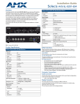
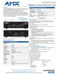
Installation Guide Solecis AVS-SL-0201-824 Overview Solecis AVS-SL-0201-824 Specifications (Cont.) The Solecis AVS-SL-0201-824 (FG1330-1113-05) is the perfect solution for all 2x1 PC switching solutions and incorporates high-resolution switching circuitry for all PC applications up to UXGA. The AVS-SL-0201-824 can be user set to operate in either manual, auto, or remote switching modes. The remote options include control from both RS-232 and Contact Closure while Auto modes allow either priority or last presented input switching. The outputs are both 75 Ohms driven with TTL sync restore for connection to long cable runs. The audio inputs automatically follow the video input and are converted to be either balanced or unbalanced signals on the output. RGB Output green = currently selected input Audio Input A (from PC 1) Number: 1 Connector: HD-15 Level: Analog Gain: Unity Impedance: 75 ohm Sync Output Input A Activity LED Input B Activity LED Level: TTL Impedance: 75 ohm Audio Output Audio Input B (from PC 2) Video Input A (from PC 1) Video Input B (from PC 2) (front) Number: 2 (L/R) Connectors: Captive-wire Type: Balanced/Unbalanced Gain: Unity Impedance: 600 ohm Power (rear) Video OUT RS232 and Contact Closure Input Voltage: 9-12VDC Power Consumption: 15W Dimensions (HWD): 1.66” x 5.85” x 4.25” (42.2 mm x 148.6 mm x 108.0 mm) • Height includes feet • Depth includes connectors Weight: 1.4 lbs. (0.65kg) Included Accessories: PS2.8 power supply (FG423-11) Certifications: • CE • FCC class B, part 15 • RoHS/WEEE compliant Audio OUT DIP Switches FIG. 1 Solecis AVS-SL-0201-824 Product Specifications Solecis AVS-SL-0201-824 Specifications RGB Input Number: 2 Connectors: HD-15 Level: Analog Max Level: 1V p-p Impedance: 75 ohm Safety Instructions Please read these instructions before using your AMX Solecis device. Failure to comply with these instructions could result in fire, electrical shock, personal injury, death, or damage to the equipment. Liquid Spills Do not set drinks on top of the unit or immerse the unit in liquid. Do Not Disassemble This device contains no user serviceable parts. All servicing must be performed by a qualified service technician. For Safety Reasons • • • • • • Sync Input Level: TTL/Analog Max Level: 5v p-p Impedance: 75 ohm • Installation 1. Audio Input Number: 2 Connectors: 3.5mm stereo Type: Unbalanced analog Max Level: 2V p-p Impedance: 47K ohm RGB Video Bandwidth: 400MHz -3dB RGB Return Loss: 45dB@10MHz, -27dB@100MHz Adjacent Input Crosstalk: 73dB@10MHz, -50dB@100MHz Audio Response: 20Hz-50KHz Do not place the unit on an unstable surface. Do not use near water or sources of heat. Use only recommended attachments. Use the type of power supply as specified. Unplug the power to the unit and refer servicing to qualified personnel under the following conditions: If liquid has been spilled or the unit has been exposed to rain or water. If it does not operate normally when the operating instructions are followed or if it exhibits a distinct change in performance indicating a need for service. If the unit has been dropped or the cabinet damaged. 2. 3. 4. 5. 6. Connect one end of the HD-15 cable to the output video socket of the computer. Connect the other end to the INPUT A socket of the switcher. Repeat for INPUT B. Connect a monitor or projector to the MAIN OUTPUT socket of the switcher. Connect Audio to the switcher Inputs using a 3.5mm Stereo Jack plug. The output is taken from the captive-wire connector on the Main Output. Video Pin Connections Contact Closure - Latching FIG. 2 provides the pin layout for the HD-15 connectors: Set Dip switches as shown in the Rear Panel DIP Switches table. • • 5 4 10 15 3 9 14 2 8 13 12 Note: When Dip switch 2 is set to Latch or RS232 all other functions will be disabled. 1 7 With control pins A and B open the unit will switch to Input B. When control pins are closed the unit will switch to Input A. 6 RS232 Mode 11 1. 2. 3. FIG. 2 RGBHV HD-15 connector The pin configuration for the HD-15 (video) connector are as follows: 1 - RED 2 - GREEN 3 - BLUE 4 - n/c 5 - n/c 6 - RED GROUND 7 - GREEN GROUND 8 - BLUE GROUND 9 - n/c 10 - SYNC GROUND 11 - n/c 12 - n/c 13 - H SYNC 14 - V SYNC 15 - n/c • • 4. Power unit down. Set Dip switches as shown in the Rear Panel DIP Switches table. Connect RS232 cable to Control pins as follows: TX - Pin A (RX) GND - Pin B (GND). Power up unit. Set system Protocol as follows • • • Baud - 9600 Data - 8 Bits Stop - 1 Bit Audio Output Switch Commands The Audio output is taken from the captive-wire connectors on the rear of the unit. Note: Numbers are shown in HEX. • • Input A For balanced output use the +, - and Gnd pins. For unbalanced output use the + and Gnd pins. Setting Up the Mode of Operation Byte 1 Byte 2 Byte3 FE 00 0A Byte 1 Byte 2 Byte3 FE 00 0B Input B Rear Panel DIP Switches Control 1 2 3 4 Notes Manual Switch Front Panel Operation Auto Switch - Normal Last Detected Input Note: When an RS232 cable is connected to the Control socket all other functions will be disabled. Auto Switch - Priority Input B Priority Auto Switch - Normal Contact Closure - Momentary Bell Button Toggle Set Dip switches as shown in the Rear Panel DIP Switches table. Contact Closure Latching Logic State Closed Input A RS232 Serial Control -switch up, -switch down, -function disabled, -switch up or down Switch Functions • • • • 1 - Manual Switch Off / On 2 - Remote Control Off / On 3 - Auto Switch Off / On 4 - Auto Switch Normal / Priority Manual Switch - Front Panel Operation 1. 2. Power up switcher. The Green LED A will light to indicate power present and A Input is switched. Set Dip switches as shown in the Rear Panel DIP Switches table. Press INPUT SELECT button to change between Input sources. 3. 4. Auto-Switching The unit scans the VERTICAL sync inputs of input A and B. If any signal sources are active the unit will switch to the last detected input. To switch between two active sources either disconnect the source and reconnect or use the laptop video toggle mode to turn the Video output off then on again (usually by holding the FN key with a Function key). To operate in auto switch mode with manual override switch Manual dip down to the On position. Auto Switch - Priority 1. 2. 3. 4. Set Dip switches as shown in the Rear Panel DIP Switches table. When a signal is applied to Input A the unit will automatically switch to A. When the signal is removed from Input A the unit will switch to Input B. To operate in auto switch mode with manual override switch Manual dip down to the On position. NOTE: Extended Display Identification Data (EDID) is passed from Input A, but is not passed from Input B. Contact Closure - Toggle Switch Set Dip switches as shown in the Rear Panel DIP Switches table. • A momentary switch can be wired across connections A and B on the rear panel. • Manual and auto switch can also be enabled or disabled in this Toggle mode of operation. For full warranty information, refer to the AMX Instruction Manual(s) associated with your Product(s). 4/11 ©2011 AMX. All rights reserved. AMX and the AMX logo are registered trademarks of AMX. AMX reserves the right to alter specifications without notice at any time. 3000 RESEARCH DRIVE, RICHARDSON, TX 75082 • 800.222.0193 • fax 469.624.7153 • technical support 800.932.6993 • www.amx.com 93-1330-1113-05 REV: F