1
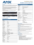
Operation/Reference Guide
AVS-SL-PR-0201-0301
Solecis Presentation Switcher
2x1:2 RGBHV, 3x1 SVID, 5x1 Stereo, CP
S ol e c i s S w it che r s
Initial Release:: 6/30/2008
AMX Limited Warranty and Disclaimer
This Limited Warranty and Disclaimer extends only to products purchased directly from AMX or an AMX Authorized Partner which
include AMX Dealers, Distributors, VIP’s or other AMX authorized entity.
AMX warrants its products to be free of defects in material and workmanship under normal use for three (3) years from the date of
purchase, with the following exceptions:
•
Electroluminescent and LCD Control Panels are warranted for three (3) years, except for the display and touch overlay components are warranted for a period of one (1) year.
•
Disk drive mechanisms, pan/tilt heads, power supplies, and MX Series products are warranted for a period of one (1) year.
•
AMX lighting products are guaranteed to switch on and off any load that is properly connected to our lighting products, as long
as the AMX lighting products are under warranty. AMX also guarantees the control of dimmable loads that are properly connected to our lighting products. The dimming performance or quality there of is not guaranteed, impart due to the random combinations of dimmers, lamps and ballasts or transformers.
•
AMX software is warranted for a period of ninety (90) days.
•
Batteries and incandescent lamps are not covered under the warranty.
•
AMX AutoPatch Epica, Modula, Modula Series4, Modula CatPro Series and 8Y-3000 product models will be free of defects in
materials and manufacture at the time of sale and will remain in good working order for a period of three (3) years following the
date of the original sales invoice from AMX. The three-year warranty period will be extended to the life of the product (Limited
Lifetime Warranty) if the warranty card is filled out by the dealer and/or end user and returned to AMX so that AMX receives it
within thirty (30) days of the installation of equipment but no later than six (6) months from original AMX sales invoice date. The
life of the product extends until five (5) years after AMX ceases manufacturing the product model. The Limited Lifetime Warranty
applies to products in their original installation only. If a product is moved to a different installation, the Limited Lifetime Warranty
will no longer apply, and the product warranty will instead be the three (3) year Limited Warranty.
All products returned to AMX require a Return Material Authorization (RMA) number. The RMA number is obtained from the AMX
RMA Department. The RMA number must be clearly marked on the outside of each box. The RMA is valid for a 30-day period. After
the 30-day period the RMA will be cancelled. Any shipments received not consistent with the RMA, or after the RMA is cancelled, will
be refused. AMX is not responsible for products returned without a valid RMA number.
AMX is not liable for any damages caused by its products or for the failure of its products to perform. This includes any lost profits, lost
savings, incidental damages, or consequential damages. AMX is not liable for any claim made by a third party or by an AMX Authorized Partner for a third party.
This Limited Warranty does not apply to (a) any AMX product that has been modified, altered or repaired by an unauthorized agent or
improperly transported, stored, installed, used, or maintained; (b) damage caused by acts of nature, including flood, erosion, or earthquake; (c) damage caused by a sustained low or high voltage situation or by a low or high voltage disturbance, including brownouts,
sags, spikes, or power outages; or (d) damage caused by war, vandalism, theft, depletion, or obsolescence.
This limitation of liability applies whether damages are sought, or a claim is made, under this warranty or as a tort claim (including
negligence and strict product liability), a contract claim, or any other claim. This limitation of liability cannot be waived or amended by
any person. This limitation of liability will be effective even if AMX or an authorized representative of AMX has been advised of the
possibility of any such damages. This limitation of liability, however, will not apply to claims for personal injury.
Some states do not allow a limitation of how long an implied warranty last. Some states do not allow the limitation or exclusion of incidental or consequential damages for consumer products. In such states, the limitation or exclusion of the Limited Warranty may not
apply. This Limited Warranty gives the owner specific legal rights. The owner may also have other rights that vary from state to state.
The owner is advised to consult applicable state laws for full determination of rights.
EXCEPT AS EXPRESSLY SET FORTH IN THIS WARRANTY, AMX MAKES NO OTHER WARRANTIES, EXPRESSED OR
IMPLIED, INCLUDING ANY IMPLIED WARRANTIES OF MERCHANTABILITY OR FITNESS FOR A PARTICULAR PURPOSE. AMX
EXPRESSLY DISCLAIMS ALL WARRANTIES NOT STATED IN THIS LIMITED WARRANTY. ANY IMPLIED WARRANTIES THAT
MAY BE IMPOSED BY LAW ARE LIMITED TO THE TERMS OF THIS LIMITED WARRANTY. EXCEPT AS OTHERWISE LIMITED
BY APPLICABLE LAW, AMX RESERVES THE RIGHT TO MODIFY OR DISCONTINUE DESIGNS, SPECIFICATIONS, WARRANTIES, PRICES, AND POLICIES WITHOUT NOTICE.
Safety Instructions
Safety Instructions
Overview
Please read these instructions before using your Solecis switcher. Failure to comply with these
instructions could result in fire, electrical shock, personal injury, death, or damage to the equipment.
Power Source
Use only a three-wire grounding type source. The power source should not exceed 264VAC. Do not
remove under any circumstances the ground wire.
Power Cord
Use only the cord shipped with the unit. Do not use the cord if it has become damaged or frayed. Contact
your Solecis dealer or call Solecis if you need to replace the power cord.
Grounding
The interface is grounded through the grounding conductor on the power cord. To avoid electric shock
plug the power cord into a properly wired receptacle. Do not defeat the purpose of the grounding-type
plug.
Fuse
For protection against the risk of fire use only a fuse of the same rating and type.
Liquid Spills
Do not set drinks on top of the unit or immerse the unit in liquid.
Do Not Disassemble
The switcher contains no user serviceable parts. All servicing must be performed by a qualified service
technician.
For Safety Reasons
Do not place the unit on an unstable surface.
Do not use near water or sources of heat.
Use only recommended attachments.
Use the correct power supply as indicated on the unit.
Unplug the unit from the mains before and refer to a qualified technician if:
the power cord has become damaged
liquid has been spilled or it has been exposed to rain or water
it does not operate correctly
it has been dropped or the cabinet damaged.
Solecis AVS-SL-PR-0201-0301 Presentation Switcher
Safety Instructions
Solecis AVS-SL-PR-0201-0301 Presentation Switcher
Table of Contents
Table of Contents
Safety Instructions .............................................................................................. a
Overview .................................................................................................................. a
Power Source............................................................................................................ a
Power Cord............................................................................................................... a
Grounding................................................................................................................. a
Fuse .......................................................................................................................... a
Liquid Spills............................................................................................................... a
Do Not Disassemble ................................................................................................. a
For Safety Reasons ................................................................................................... a
Overview ............................................................................................................1
Product Specifications ............................................................................................. 2
Connections ........................................................................................................5
PC Connections......................................................................................................... 5
Video Connections.................................................................................................... 5
Audio Connections.................................................................................................... 5
Microphone Connections ................................................................................................ 5
Balanced Output Connections......................................................................................... 5
Serial Control Connections ....................................................................................... 6
Configuration .....................................................................................................7
Overview .................................................................................................................. 7
Microphone Setup .................................................................................................... 8
Display Setup............................................................................................................ 8
Sources Setup ........................................................................................................... 9
Locking Buttons ........................................................................................................ 9
Operation .........................................................................................................11
Power On................................................................................................................ 11
Power Off ............................................................................................................... 11
PC1 & PC2 .............................................................................................................. 11
Video 1, 2 & 3......................................................................................................... 11
AUX ........................................................................................................................ 11
Mute / Blank ........................................................................................................... 11
Mode ...................................................................................................................... 11
Volume Up & Down ................................................................................................ 11
Mic Mix ................................................................................................................... 11
Mic Mute................................................................................................................. 11
Solecis AVS-SL-PR-0201-0301 Presentation Switcher
i
Table of Contents
Serial Commands ..............................................................................................13
Communication Protocol......................................................................................... 13
Command Set ........................................................................................................ 13
Decoding the Front Panel Status ........................................................................... 14
Troubleshooting ...............................................................................................15
ii
Solecis AVS-SL-PR-0201-0301 Presentation Switcher
Overview
Overview
The Solecis AVS-SL-PR-0201-0301 Presentation Switcher (FG1330-2020-01) combines switching of
PC, computer, video and audio for presentation and conference rooms, home cinema, AV Rental
Companies and any environment where a number of mixed source types need to be displayed.
(front)
(rear)
FIG. 1 Solecis AVS-SL-PR-0201-0301 Presentation Switcher
The AVS-SL-PR-0201-0301 features a total of 5 AV inputs and a programmable serial output for
controlling projectors, plasma and LCD displays.
There are 2 wide-band (250MHz -3dB) computer inputs on HD-15 connectors, 3 video inputs each of
which can be either composite or YC. 5 stereo audio follow-video/computer inputs on RCA/CaptiveWire connectors each with independent volume control and preset input attenuation which is retained
within the non-volatile memory of the AVS-SL-PR-0201-0301.
Full video and audio breakaway is available with RS232 control along with a master volume control for
total flexibility. Regardless of the video input type (CV or YC), both CV and YC outputs are available
simultaneously which allows mixed format inputs to be displayed without switching.
The AVS-SL-PR-0201-0301 also supports a balanced microphone (with phantom power if required) for
which the gain and tone can easily be adjusted from the PC based setup software. The microphone input
can be mixed onto the switched audio output and is then presented on a balanced mixed output.
Control of the AVS-SL-PR-0201-0301 can be from the front panel or by RS232 control from a computer
or AV control system. The programmable serial output will control power on and off and switch the
inputs of the projector or display. It is easily programmed using the Solecis Device Configuration
Software which includes a library of common display devices to reduce installation time.
Projector control includes programmable RS232 commands for Power ON/OFF, RGB, YC and CV
inputs and when supported, the devices power status is interrogated and displayed on the front panel.
Solecis AVS-SL-PR-0201-0301 Presentation Switcher
1
Overview
Product Specifications
AVS-SL-PR-0201-0301 Specifications
RGB
RGB Inputs:
2
Connector:
HD-15
Level:
Analog
Max Level:
1V p-p
Impedance:
75 ohm
Bandwidth
250MHz -3dB
Return Loss
-38dB @ 10MHz, -20dB @ 100MHz
Adjacent Input Crosstalk: -80dB @ 10MHz, -70dB @ 100MHz
Sync Input
Level:
TTL / Analog
Max Level:
5V p-p
Impedance:
75 ohm
Video Input
Number:
3
Connectors:
RCA & 4 pin mini din S-Video
Type:
CV or YC
Bandwidth:
50 MHz -3dB
Differential Phase Error:
0.05%
Differential Gain Error:
0.03%
Crosstalk:
-60dB @ 1MHz
Audio Input
Number:
6
Level:
Analog
Connector:
RCA
Type:
Unbalanced analog
Max Level
2V p-p
Impedance
47K ohm
Audio Response
20Hz - 50KHz
Microphone
Balanced / Unbalanced
Phantom Power
12V internal / 48V max external
RGB Output
2
Number:
2
Connector:
HD-15
Level:
Analog
Gain:
Unity
Sync
Output
Impedance:
75 ohm
Sync Level:
TTL
Sync Impedance:
75 ohm
Solecis AVS-SL-PR-0201-0301 Presentation Switcher
Overview
AVS-SL-PR-0201-0301 Specifications (Cont.)
Video Output
Number
2
Connectors
RCA & 4 pin mini din S-Video
Audio Output
Connector
RCA & Captive-wire
Switched
1 unbalanced with volume control
Mixed
1 balanced / unbalanced
Impedance
600 ohm
Power:
• 110-240V 50/60Hz
Power Consumption:
15W
Dimensions (HWD):
44 x 441 x 174
Weight:
1.4kg
• Power Connector: IEC
Included Accessories:
1U Rack mounting kit
Certifications:
• CE
• UL60950
• FCC class B, part 15
• RoHS/WEEE compliant
Solecis AVS-SL-PR-0201-0301 Presentation Switcher
3
Overview
4
Solecis AVS-SL-PR-0201-0301 Presentation Switcher
Connections
Connections
Make sure the unit is unplugged from the mains power source while making initial
connections.
PC Connections
1. Connect the PC sources to the sockets labelled PC 1 & PC 2.
2. Connect the primary output to Output 1 and then if a secondary output is required, connect it to
Output2.
3. Connect the audio sources for the PC inputs to the inputs labelled PC 1 & PC 2 in the audio block.
Video Connections
1. Connect the Composite and S-Video sources to the inputs labelled Video 1, Video 2 & Video 3.
2. Connect the corresponding audio input to it's socket in the audio block.
3. Connect the video display device to either the composite output and/or the S-Video output.
Do not connect a composite and s-video input to the same input, this may damage
the equipment.
Only the video output should ever have both connections populated.
Audio Connections
1. If an auxiliary audio input is required then connect it to the input labelled AUX in the audio block.
2. Connect the audio output to the input of the chosen amplifier or other audio device.
Microphone Connections
The unit comes with an internal 12V supply for use as microphone phantom power. If this is not required
or a separate phantom power supply is required then make sure the phantom power supply switch is set
to the off position.
Make sure the phantom power settings are correct before connecting the microphone
to avoid damage to equipment.
Do not exceed 48v phantom power supply, exceeding this limit may result in fire.
If a separate phantom power supply is required connect it to the screw terminals labelled Power + and
gnd.
Connect the microphone to the balanced input labelled Mic +, - and gnd.
Balanced Output Connections
If balanced audio output is required connect it to the screw terminals labelled balanced output left &
right, hot & cold and ground.
Solecis AVS-SL-PR-0201-0301 Presentation Switcher
5
Connections
Serial Control Connections
Connect the display device serial control to the screw terminals labelled Display Tx & Rx.
For setting up the equipment and for remote control of the switch connect to the PC Comms Tx & Rx
terminals.
The ground terminal is shared between the two connections.
Don't forget to cross connect the serial devices so the TX goes to RX and RX goes to
TX and GROUND goes to GROUND.
Please double check all connections before connecting power to the unit.
6
Solecis AVS-SL-PR-0201-0301 Presentation Switcher
Configuration
Configuration
Overview
In order to correctly set up the AVS-SL-PR-0201-0301 switch please download the Solecis Device
Manager software from our website - www.Solecis.co.uk then click on support. Once installed, make
sure the switch is connected correctly to a PC serial port and then start the device installer software. The
software will scan the serial ports on the PC and find the attached device (FIG. 2).
FIG. 2 Attached Devices
Double click on the required port and the devices front control status will then be displayed (FIG. 3).
FIG. 3 Switch Status Monitor
FIG. 3 shows the PC control panel for the AVS-SL-PR-0201-0301, it replicates exactly what is seen on
the front of the unit. Clicking on a button on the screen will have the same effect as manually pressing
the equivalent button. Click on the Unit Address to change the value set for installation where multiple
addressable units are required. When the reset interface option is checked then every time the power
supply to the unit is reset, it will initialise itself into the default mode of PC 1 selected with no mix, no
mute and the mode set to AV.
Solecis AVS-SL-PR-0201-0301 Presentation Switcher
7
Configuration
Microphone Setup
Clicking the set up microphone button brings up the window shown in FIG. 4. Dragging the arrows
allows increase and decrease of a setting whilst centre all sets the values back to their middle value.
FIG. 4 Microphone setup
To return to the main screen click on back.
Display Setup
Click on the set up display device button brings up the window shown in FIG. 5. From here you can tell
the switcher what device is attached by selecting the make, type and model from the list.
FIG. 5 Setting up the display device
The video source selection tells the switcher which input you are using on the display device. For
example in FIG. 5, when a video input button is pressed, the display device would switch to it's
composite input and if the S-Video option were checked then it would switch to it's S-Video input. There
is no option to select which PC input the display device switches to when a PC input button is pressed,
this will always be PC1 in the library. If a different input is required then the library must be edited for
the desired results.
Having the use power interrogation checked will allow (if supported by the display device) the display
on / off buttons on the switcher to reflect the real status of the display device and not just what was last
pressed. This means that if the display device is turned off say for example via the remote control then
the switcher would reflect this information back to the switch panel by lighting the power off button.
When ready, click on Change Display to save the settings into the switch.
8
Solecis AVS-SL-PR-0201-0301 Presentation Switcher
Configuration
Sources Setup
Clicking on set up sources brings up FIG. 6. This allows you to set the volume attenuation levels for each
of the audio inputs. When the master volume on the front panel is adjusted, it adjusts all of the input
volume controls up to the point where the first input hits the maximum or minimum. This means the if
for example PC1 input slider was higher than PC2 then you would never be able to get PC2's volume to
the maximum because it would stop when PC1's volume reached that point.
FIG. 6 Set up sources
Here is where the video input types are also set. From FIG. 6 the input to video 1 would be S-Video, to
video 2 would be composite and video 3 would also be S-Video.
Click Back to return to the main screen.
Locking Buttons
The lock buttons option allows you to select buttons that are disabled to the user (FIG. 7).
FIG. 7 Set up sources - Lock Buttons
The button lockout selection mode is indicated by the lock buttons control turning red and then when a
control button is clicked the corresponding control also turns red. The items that are red are the buttons
that will not be available from the front panel. Once the required buttons are selected, clicking on the
lock buttons control will save the settings and restart the unit.
Even if a button is disabled on the front panel, you will still be able to action it by
sending the appropriate RS232 command into the PC Control port.
Solecis AVS-SL-PR-0201-0301 Presentation Switcher
9
Configuration
10
Solecis AVS-SL-PR-0201-0301 Presentation Switcher
Operation
Operation
Power On
This button turns the display device on, the button lights to show the current status.
Power Off
This button turns the display device off, the butt on lights to show the current status.
PC1 & PC2
These button allow input selection of the two PC inputs. The button lights to reflect the press.
Video 1, 2 & 3
Same as PC1 & PC2 but for the video inputs.
AUX
Same again but for the auxiliary audio input. This can only be selected in AV & Audio modes.
Mute / Blank
Blanks the video and mutes the audio in AV mode, blank in video mode and mute in audio.
Mode
Toggles between the three modes, AV, Video and Audio.
Volume Up & Down
Used to control the volume of the line level output. This control is a master volume control and thus
affects all of the input volume levels but does not change the differences in attenuation. There fore once
the input with the highest attenuation level reaches minimum volume, the volume cannot be reduced any
more regardless of the current input level. The same applies for increasing the volume.
Mic Mix
When selected, the switched audio is combined with the microphone onto the balanced output. By
holding the mix button for 2-3 seconds, the unit is placed in microphone volume adjust mode. The
volume control lights will flash and at which point the volume buttons will now control the microphone
volume level only. Holding the mix button in for a further 2-3 seconds takes the unit back to normal
operation and the buttons stop flashing.
Mic Mute
Mutes the microphone input when selected.
When the device is in audio breakaway mode, the input that is highlighted is the last button pressed, it
does not necessarily reflect the full extents of the switcheroo current status. For example if in AV mode
that PC1 was selected then the mode was change to video mode and Video 1 was selected then video 1
would be displayed but the audio would still be set the PC1 and not be reflected on the display at all.
Solecis AVS-SL-PR-0201-0301 Presentation Switcher
11
Operation
12
Solecis AVS-SL-PR-0201-0301 Presentation Switcher
Serial Commands
Serial Commands
Communication Protocol
Baud - 9600
Data Bits - 8
Stop Bits - 1
Parity - None
Command Set
Serial Commands
Command
Description
Acknowledge
Returned
F2 09 EA 80
Requests Solecis device code – Header 6E, 2020 = 1D
6E 1D
9F 15 05
Simulates display device power on button
9F 15 05
9F 15 06
Simulates display device power off button
9F 15 06
9F 15 07
Simulates PC1 input button
9F 15 07
9F 15 08
Simulates PC2 input button
9F 15 08
9F 15 09
Simulates Video 1 input button
9F 15 09
9F 15 0A
Simulates Video 2 input button
9F 15 0A
9F 15 0B
Simulates Video 3 input button
9F 15 0B
9F 15 0C
Simulates AUX input button
9F 15 0C
9F 15 0D
Simulates mute / blank button
9F 15 0D
9F 15 0E
Simulates Mode button
9F 15 0E
9F 15 0F
Simulates Volume up button
9F 15 0F
9F 15 10
Simulates Volume down button
9F 15 10
9F 15 11
Simulates Microphone mix button
9F 15 11
9F 15 12
Simulates Microphone mute button
9F 15 12
9F 15 13
Requests front panel display status
9F 15 13
9F 15 14 VV
See below for information on decoding the returned data.
xx xx xx xx
Sets the microphone volume (max 00 < VV < 80 min)
9F 15 14 VV
9F 15 15 01 VV Sets the microphone gain (00 < VV < FF)
9F 15 15 01 VV
9F 15 15 02 VV Sets the microphone bass (00 < VV < FF)
9F 15 15 02 VV
9F 15 15 04 VV Sets the microphone mid (00 < VV < FF)
9F 15 15 04 VV
9F 15 15 08 VV Sets the microphone treble (00 < VV < FF)
9F 15 15 08 VV
9F 15 17 VV
Sets the master volume (max 00 < VV < 80 min)
9F 15 17 VV
9F 15 18
Requests the master volume (max 00 < VV < 80 min)
9F 15 18 VV
9F 15 1A
Microphone Volume Up
9F 15 1A
9F 15 1B
Microphone Volume Down
9F 15 1B
9F 15 1C
Microphone Mix On
9F 15 1C
9F 15 1D
Microphone Mix Off
9F 15 !D
9F 15 1E
Microphone Mute On
9F 15 1E
9F 15 1F
Microphone Mute Off
9F 15 1F
9F 15 20
AV Mode
9F 15 20
Solecis AVS-SL-PR-0201-0301 Presentation Switcher
13
Serial Commands
Serial Commands (Cont.)
9F 15 21
Audio Mode
9F 15 21
9F 15 22
Video Mode
9F 15 22
9F 15 40
PC Blank On
9F 15 40
9F 15 41
PC Blank Off
9F 15 41
9F 15 44
Video Blank On
9F 15 44
9F 15 45
Video Blank Off
9F 15 45
9F 15 48
Audio Mute On
9F 15 48
9F 15 49
Audio Mute Off
9F 15 49
These commands are global, if you have a unit address set these commands will override the address and
still switch the unit. If you want to send addressed only codes out then you should replace the second
byte by the units address.
So for example if Unit 1 was set to address 1 and Unit 2 to address 2 then:
9F 02 08 would set unit 2 to PC2 input
9F 01 0B would set unit 1 to Video 3 input
Decoding the Front Panel Status
Byte No.
Bits 8:7
Bits 6:5
Bits 4:3
Bits 2:1
1
Display On
Display Off
PC1
PC2
2
Video 1
Video 2
Video 3
Aux
3
Blank / Mute
Mode
Volume Up
Volume Down
4
Microphone Mix
Microphone Mute
Current Switch Mode
Then decode the 2 bits to give the relevant indicators status:
0:0 = Off
0:1 = On
1:0 = Flash
And the current switch mode:
0001 = AV Mode
0010 = Video mode
0100 = Audio mode
14
Solecis AVS-SL-PR-0201-0301 Presentation Switcher
Troubleshooting
Troubleshooting
Q. Device Installer can't find my switch.
Make sure that the serial connections are wired correctly, tx to rx, rx to tx and ground to
ground.
If using a USB adapter, try removing it and plugging it in to a different USB port on the PC.
Make sure the PC is connected to the PC communications port and not the display's
communication port.
Q. My display device does not respond to button presses.
Make sure the system is configured for the correct display device.
Make sure the serial connections to the display device are correct, tx to rx, rx to tx and ground
to ground.
If the display power buttons flash for a second after pressing one then there is no display
device configured for use with the switch. See section 3 on configuring the switch.
Make sure the communication settings are correct, have a look in the library files to do this.
Make sure there is power to the display device and that there is no internal settings to allow
serial communications which must first be turned on.
Q. Can I control multiple display devices.
A. Yes as long as they are all the same command set then you can connect the tx line from the switch to as
many display device as required. The rx however should only be connect to a single display device, leave
the rest of the displays detached.
Q. The front panel says the switch is set to PC1 but the audio is coming from Video 1.
A. Check that the switch is in AV mode, if not press the mode button until it is in AV mode and select the
input again.
Q. Can I mix the microphone onto the RCA audio output?
A. No, but you can connect the left and right hot (L+ & R+) from the balanced output to the amplifier,
then select mic mix and both sources will be present at equivalent to line levels.
Q. How do I reset the switch?
A. Disconnect the power to the device, hold in the display power on & off buttons and reconnect power
to the switch. All 3 mode lights should be illuminated to acknowledge the reset. Reset the power once
more to resume normal operation. If necessary attach a computer and reprogram the device.
Solecis AVS-SL-PR-0201-0301 Presentation Switcher
15
Troubleshooting
16
Solecis AVS-SL-PR-0201-0301 Presentation Switcher
Troubleshooting
Solecis AVS-SL-PR-0201-0301 Presentation Switcher
17
AMX. All rights reserved. AMX and the AMX logo are registered trademarks of AMX. AMX reserves the right to alter specifications without notice at any time.
©2008
6/08
It’s Your World - Take Control™
3000 RESEARCH DRIVE, RICHARDSON, TX 75082 USA • 800.222.0193 • 469.624.8000 • 469-624-7153 fax • 800.932.6993 technical support • www.amx.com