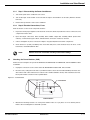
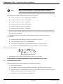
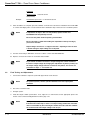
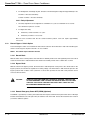
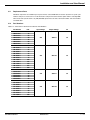
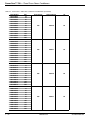
1
w w w. m g e o p s . c o m
Power-Sure™
Three Phase
Power Conditioners
Installation and User Manual
Power-Sure™ 700 — Three Phase Power Conditioners
IMPORTANT SAFETY INSTRUCTIONS
SAVE THESE INSTRUCTIONS – This manual contains important instructions for Power-Sure™ 700 that must be
followed during operation of the equipment.
WARNING
Opening enclosures expose hazardous voltages. Always refer service to
qualified personnel only.
ATTENTION
L'ouverture des cabinets expose des tensions dangereuses. Assurez-vous
toujours que le service ne soit fait que par des personnes qualifiees.
WARNUNG!
Das öffnen der Gehäuse legen gefährliche Spannungen bloss. Service
sollte immer nur von qualifizierten Personal durchgeführt werden.
WARNING
As standards, specifications, and designs are subject to change, please
ask for confirmation of the information given in this publication.
ATTENTION
Comme les normes, spécifications et produits peuvent changer, veuillez
demander confirmation des informations contenues dans cette publication.
WARNUNG!
Normen, Spezifizierungen und Pläne unterliegen Anderungen. Bitte verlangen Sie eine Bestätigung über alle Informationen, die in dieser Ausgabe
gemacht wurden.
NOTE
This equipment has been tested and found to comply with the limits for a
Class A digital device, pursuant to part 15 of the FCC rules. These limits
are designed to provide reasonable protection against harmful interference
when the equipment is operated in a commercial environment.
This equipment generates, uses, and can radiate radio frequency energy
and, if not installed and used in accordance with the instruction manual,
may cause harmful interference to radio communications. Operation of this
equipment in a residential area is likely to cause harmful interference in
which case the user will be required to correct the interference at user's
own expense.
Certification Standards
◗
ANSI/IEEE C57.12.91 Standards
◗
IEEE C62.41 cat.A3
◗
NFPA 70 – National Electrical Code
◗
FCC rules and regulations of Part 15, Subpart J, Class A
◗
UL listed under 1012, Power Supplies - General Purpose
◗
NEMA PE 1 (National Electrical Manufacturers Association)
◗
NEMA 250 (National Electrical Manufacturers Association)
– Enclosures for Electrical Equipment (1000 Volts Maximum)
ii
◗
ISO 9001
◗
Occupational Safety & Health Administration (OSHA)
Important Safety information
86-108814-00 B01
Installation and User Manual
WARNING
To reduce the risk of fire or electric shock, install in a temperature and
humidity controlled indoor area free of conductive contaminants.
This equipment is intended only for installations in a RESTRICTED
ACCESS LOCATION.
ATTENTION
Pour réduire le riske d'inccendie ou d'électrocution, installer dans une
enciente intérieure contrôlée en température et humidité et sans
contaminants conducteurs.
Ce matériel est destiné seulement pour des installations dans un
EMPLACEMENT RESTREINT d'cAccès.
WARNUNG!
Um die Gefahr von Feuer und elektrischem Schock zu reduzieren, muss
das Gerät in einem temperatur – und feuchtigkeitskontrollierten Raum, frei
von leitungsfähigen Verunreinigungen, installiert werden. Dieses Gerät ist
nur für die Installation an einem Ort mit eingeschränkter Zugangserlaubnis
vorgesehen.
Diese Ausrüstung ist nur für Anlagen in einem EINGESCHRäNKTEN
ZUGRIFF STANDORT bestimmti.
WARNING
HIGH LEAKAGE CURRENT. Earth connection essential before connecting
supply.
ATTENTION
COURANT DE FUITE ELEVE. Raccordement a la terre indispensable avant le
raccordement au reseau.
WARNUNG!
Hoher Ableitstrom Vor Inbetriebnahme Schutzleiterverbindung herstellen.
How to use this manual and Symbol Usage
This manual is designed for ease of use and easy location of information.
Locate specific topics in the Table of Contents.
Typographical conventions use single quote marks in procedures to denote a prompt for user action:
For example: 1. After the selections are complete, click on the “Save” button.
This manual uses four icon symbols with text to convey important information and tips.
86-108814-00 B01
WARNING
indicates information provided to protect the user and service personnel against
safety hazards and/or possible equipment damage.
CAUTION
indicates information provided to protect the user and service personnel against
possible equipment damage.
IMPORTANT
indicates information provided as an operating instruction, or as an operating tip.
NOTE
indicates information provided as an operating tip or an equipment feature.
How To Use This Manual
iii
Power-Sure™ 700 — Three Phase Power Conditioners
CAUTION: Record All Serial Numbers!
RECORD ALL SERIAL NUMBERS FOR THE POWER-SURE™ 700 AND COMPONENTS.
THESE SERIAL NUMBERS WILL BE REQUIRED IF YOUR SYSTEM NEEDS SERVICE.
KEEP THIS MANUAL IN A PLACE WHERE YOU CAN REFERENCE THE SERIAL
NUMBERS IF SERVICE IS REQUIRED!
POWER-SURE™ 700 SERIAL NUMBER: _______________________________________________
ADDITIONAL SERIAL NUMBERS:
iv
____________________________
______________________________
____________________________
______________________________
____________________________
______________________________
____________________________
______________________________
____________________________
______________________________
____________________________
______________________________
____________________________
______________________________
____________________________
______________________________
____________________________
______________________________
____________________________
______________________________
CAUTION: Record All Serial Numbers
86-108814-00 B01
Installation and User Manual
Power-Sure™ 700
Three Phase
Power Conditioners
Installation and User Manual
Revision History
Power-Sure™ 700 Three Phase Power Conditioners Installation and User Manual
Revision:
A00
Initial Release
09/2003
A01
ECN#: 003787
02/2004
B00
ECN#: 004681
08/2006
B01
ECN#: 005088
12/2006
86-108814-00
Copyright © 2007 MGE Office Protection Systems
All rights reserved. Printed in U.S.A.
MGE Office Protection Systems
13 Whatney, Suite #101
Irvine, CA 92618
(949) 268-2800
For Technical Support, Customer Care Center, or Customer FAQ,
please visit our website: www.mgeops.com or call (800) 279-7776
86-108814-00 B01
v
Power-Sure™ 700 — Three Phase Power Conditioners
(This page left blank intentionally)
vi
86-108814-00 B01
Installation and User Manual
Contents
section
description . . . . . . . . . . . . . . . . . . . . . . . . . . . . . . . . . . . . . . . . . . .page
IMPORTANT SAFETY INSTRUCTIONS . . . . . . . . . . . . . . . . . . . . . . .ii
Certification Standards . . . . . . . . . . . . . . . . . . . . . . . . . . . . . . . . . . . . .ii
How to Use This Manual and Symbol Usage . . . . . . . . . . . . . . . . . . .iii
CAUTION: Record All Serial Numbers! . . . . . . . . . . . . . . . . . . . . . . . .iv
Revision History . . . . . . . . . . . . . . . . . . . . . . . . . . . . . . . . . . . . . . . . . .v
Section 1
Introduction
section
description . . . . . . . . . . . . . . . . . . . . . . . . . . . . . . . . . . . . . . . . . . .page
1.0
1.1
1.2
1.3
Scope . . . . . . . . . . . . . . . . . . . . . . . . . . . . . . . . . . . . . . . . . . . . . .1 — 1
Reference Manuals . . . . . . . . . . . . . . . . . . . . . . . . . . . . . . . . . . .1 — 1
Section Descriptions . . . . . . . . . . . . . . . . . . . . . . . . . . . . . . . . . . .1 — 1
Receiving and Inspection Notes . . . . . . . . . . . . . . . . . . . . . . . . . .1 — 2
Location and Storage . . . . . . . . . . . . . . . . . . . . . . . . . . . . . . . . . .1 — 2
General Description . . . . . . . . . . . . . . . . . . . . . . . . . . . . . . . . . . .1 — 2
Electrical and Performance Specifications . . . . . . . . . . . . . . . . . 1 — 3
Main Transformer Specification . . . . . . . . . . . . . . . . . . . . . . . . . .1 — 3
Input Breaker . . . . . . . . . . . . . . . . . . . . . . . . . . . . . . . . . . . . . . . .1 — 4
Monitoring the Power-Sure™ 700 . . . . . . . . . . . . . . . . . . . . . . . .1 — 4
Protection for the Power-Sure™ 700 . . . . . . . . . . . . . . . . . . . . . .1 — 4
1.3.1
1.4
1.4.1
1.4.2
1.4.3
1.5
1.6
Section 2
Installation and Operation
section
description . . . . . . . . . . . . . . . . . . . . . . . . . . . . . . . . . . . . . . . . . . .page
2.0
2.1
2.2
2.3
Scope . . . . . . . . . . . . . . . . . . . . . . . . . . . . . . . . . . . . . . . . . . . . . .2 — 1
Installation Notes . . . . . . . . . . . . . . . . . . . . . . . . . . . . . . . . . . . . .2 — 1
MGE Office Protection Systems Power-Sure™ 700 . . . . . . . . . .2 — 1
Power-Sure™ 700 Installation Drawings and
Cabinet Dimensions . . . . . . . . . . . . . . . . . . . . . . . . . . . . . . . . . . .2 — 2
General Operation Notes . . . . . . . . . . . . . . . . . . . . . . . . . . . . . . .2 — 5
Power-Sure™ 700 Cable Connections . . . . . . . . . . . . . . . . . . . .2 — 6
Input Wire Size, Grounding and Output Wiring . . . . . . . . . . . . . .2 — 6
Start-up Sequence . . . . . . . . . . . . . . . . . . . . . . . . . . . . . . . . . . . .2 — 8
2.4
2.5
2.5.1
2.6
86-108814-00 B01
Contents
ci
Power-Sure™ 700 — Three Phase Power Conditioners
Section 3
Maintenance
section
3.0
3.1
3.2
3.3
3.4
3.5
3.6
3.7
3.8
3.9
3.10
3.11
3.12
description . . . . . . . . . . . . . . . . . . . . . . . . . . . . . . . . . . . . . . . . . . .page
Scope . . . . . . . . . . . . . . . . . . . . . . . . . . . . . . . . . . . . . . . . . . . . . .3 — 1
Preventive Maintenance . . . . . . . . . . . . . . . . . . . . . . . . . . . . . . . .3 — 1
Power-Sure™ 700 Performance Checklist . . . . . . . . . . . . . . . . . .3 — 2
Troubleshooting Guide . . . . . . . . . . . . . . . . . . . . . . . . . . . . . . . . 3 — 4
Troubleshooting Power Line and Electrical Connections . . . . . . .3 — 5
3.3.1 Step 1. Disassembling the Power Conditioners . . . . . . . . . . . . . .3 — 5
3.3.2 Step 2. Electrical Connections, Fuses . . . . . . . . . . . . . . . . . . . . .3 — 5
Checking the Power Modules (SCR) . . . . . . . . . . . . . . . . . . . . . .3 — 5
Check SCR Snubber Card . . . . . . . . . . . . . . . . . . . . . . . . . . . . . .3 — 6
3.5.1 Check Control Card and Filter Card . . . . . . . . . . . . . . . . . . . . . . .3 — 7
Final Testing and Adjustments . . . . . . . . . . . . . . . . . . . . . . . . . . .3 — 8
Unit Component Location Diagrams . . . . . . . . . . . . . . . . . . . . . .3 — 9
SCR Heat Sink Assemblies . . . . . . . . . . . . . . . . . . . . . . . . . . . .3 — 12
Field Adjustments of Circuit Cards . . . . . . . . . . . . . . . . . . . . . . .3 — 15
3.9.1 Power-Sure™ 700 Control Card #49120/407415 . . . . . . . . . . .3 — 15
3.9.2 Control Card Adjustment Procedure . . . . . . . . . . . . . . . . . . . . . .3 — 16
3.9.3 Over/Under Voltage Detection Board #35867 . . . . . . . . . . . . . .3 — 17
3.9.3.1 Undervoltage Adjustment . . . . . . . . . . . . . . . . . . . . . . .3 — 17
3.9.3.2 Overvoltage Adjustment . . . . . . . . . . . . . . . . . . . . . . . .3 — 17
3.9.3.3 Delay Adjustment . . . . . . . . . . . . . . . . . . . . . . . . . . . . .3 — 18
Manual Bypass Switch Option . . . . . . . . . . . . . . . . . . . . . . . . . .3 — 18
3.10.1 Normal Mode . . . . . . . . . . . . . . . . . . . . . . . . . . . . . . . . . . . . . . .3 — 18
3.10.2 Bypass Mode . . . . . . . . . . . . . . . . . . . . . . . . . . . . . . . . . . . . . . .3 — 18
3.10.3 Remote Emergency Power OFF (REPO) (Optional) . . . . . . . . .3 — 18
Replacement Parts . . . . . . . . . . . . . . . . . . . . . . . . . . . . . . . . . .3 — 19
Parts Numbers . . . . . . . . . . . . . . . . . . . . . . . . . . . . . . . . . . . . . .3 — 19
Appendices
Appendix A
A-1:
A-2:
A-3:
10-50kVA Wiring Diagram . . . . . . . . . . . . . . . . . . . . . . . . . . . . . .A — 1
75-150kVA Wiring Diagram . . . . . . . . . . . . . . . . . . . . . . . . . . . . .A — 2
125-300kVA Wiring Diagram . . . . . . . . . . . . . . . . . . . . . . . . . . . .A — 3
Technical Support and Field Service . . . . . . . . . . . . . . . . . . . . . . . . . . . . . . . . . . . . . .W — 3
MGE Office Protection Systems Service and Repair
Who to Contact
Scheduling Field Service Engineer Support
Return for Repair (RMA)
c ii
Contents
86-108814-00 B01
Installation and User Manual
Figures
figure description . . . . . . . . . . . . . . . . . . . . . . . . . . . . . . . . . . . . . . . . . . . . . . . . .page
2-1:
2-2:
2-3:
2-4:
Power-Sure™
Power-Sure™
Power-Sure™
Power-Sure™
700
700
700
700
—
—
—
—
10-15kVA Mechanical Cabinet Measurements . . .2 — 2
25-30kVA Mechanical Cabinet Measurements . . .2 — 3
45-150kVA Mechanical Cabinet Measurements . .2 — 4
225-300kVA Mechanical Cabinet Measurements .2 — 5
3-1:
3-2:
3-3:
3-4:
3-5:
3-6:
Power Module . . . . . . . . . . . . . . . . . . . . . . . . . . . . . . . . . . . . . . . . . . . . .3 — 5
Test Wire Diagram . . . . . . . . . . . . . . . . . . . . . . . . . . . . . . . . . . . . . . . . . .3 — 6
Power-Sure™ 700 — 10-15kVA Major Components . . . . . . . . . . . . . . . .3 — 9
Power-Sure™ 700 — 25-30kVA Major Components (Rear View) . . . . . .3 — 9
Power-Sure™ 700 — 45-150kVA Major Components (Rear View) . . . .3 — 10
Power-Sure™ 700 — 225-300kVA Cable Connections,
Input Output Locations. . . . . . . . . . . . . . . . . . . . . . . . . . . . . . . . . . . . . .3 — 11
3-7: Power-Sure™ 700 — 10-30kVA SCR Heatsink Assembly . . . . . . . . . .3 — 12
3-8: Power-Sure™ 700 — 45-50kVA SCR Heatsink Assembly . . . . . . . . . .3 — 13
3-9: Power-Sure™ 700 — 75-150kVA SCR Heatsink Assembly . . . . . . . . .3 — 14
3-10: Power-Sure™ 700 — 225-300kVA SCR Heatsink Assembly . . . . . . . .3 — 15
3-11: Power-Sure™ 700 Controller Card (Top View) . . . . . . . . . . . . . . . . . . .3 — 16
Tables
table description . . . . . . . . . . . . . . . . . . . . . . . . . . . . . . . . . . . . . . . . . . . . . . . . .page
86-108814-00 B01
2-1:
2-2:
480 VAC Input and 208 VAC Output Wire Size Chart . . . . . . . . . . . . . . .2 — 7
208 VAC Input and 208 VAC Output Wire Size Chart . . . . . . . . . . . . . . .2 — 7
3-1:
Power-Sure™ 700 Power Conditioners Part Numbers . . . . . . . . . . . . .3 — 19
Contents
c iii
Power-Sure™ 700 — Three Phase Power Conditioners
(This page left blank intentionally)
c iv
86-108814-00 B01
Installation and User Manual
Introduction
1.0
Scope
This section is a general description of the Power-Sure™ 700 Three Phase Power Conditioners. Includes receiving,
location and storage, electrical, mechanical specifications, monitoring, and internal protection for components.
1.1
Reference Manuals
N/A
1.2
Section Descriptions
This manual is divided into three sections:
Section 1: Introduction
This section is a general description of the Power-Sure™ 700 Three Phase Power Conditioners. It includes receiving,
location and storage, electrical and mechanical specifications, monitoring and internal protection for components.
Section 2: Installation and Operation
This section describes installation requirements, system dimensions, cable connections, and start-up procedures
for the Power-Sure™ 700 Three Phase Power Conditioners.
Section 3: Maintenance
This section contains preventive maintenance for the Power-Sure™ 700, electrical connection troubleshooting,
checking power modules (SCR), voltage adjustments, and PCB card troubleshooting to assist the user with communication and configuration connections.
86-108814-00 B01
Introduction
1—1
Power-Sure™ 700 — Three Phase Power Conditioners
1.3
Receiving and Inspection Notes
Before accepting the shipment from the freight carrier, inspect the exterior surfaces of all shipping containers or
packaging used, and the equipment, for damage that may have occurred during transit. If the shipping containers
or equipment shows evidence of damage, note the damage on the receiving document (bill of lading) prior to signing
for receipt of equipment.
ALL CLAIMS FOR SHIPPING DAMAGE MUST BE FILED DIRECTLY WITH THE CARRIER. Replacements for
damaged components should be ordered through MGE Office Protection Systems.
Check by thorough inspection if any electrical connections have become loose because of vibration during
shipment. Remove top and side panels (Not applicable on 225kVA and larger).
Check the nameplate to be sure that the voltage and frequency match the available power supply. Under no circumstance should the unit be connected to a power source which does not conform to the nameplate rating.
1.3.1
Location and Storage
The unit has been completely inspected and extensively tested under various load conditions prior to shipment.
Care to install it at a proper location will assure long trouble free operation. The unit is forced air cooled with the air
intake at the bottom, front or sides and exhausts out at the top or rear. Therefore, it should be installed in a clean,
dry place with enough clearance to allow a free flow of air.
Allow at least 4 inches of space between the unit and the wall or other equipment for portable units.
Allow enough space for maintenance as indicated on the cabinet outlines. See Section 2.0, Figures 2-1 thru 2-4. If
the equipment is to be stored prior to installation, it should be stored in a cool, dry, well-ventilated location that is
protected from rain, splashing water, chemical agents, etc. The equipment should be covered with a tarpaulin or
plastic wrapper to protect it against dust, dirt, paint, or other foreign materials.
1.4
General Description
The Power-Sure™ 700 is a continuous duty power conditioner designed to supply reliable, clean regulated power to
critical loads. An efficient design with state of the art micro-processor controlled solid state devices provide immunity
to all line disturbances. The cabinet is a heavy gauge industrial steel throughout. Metal is anti-corrosive phosphate
treated prior to paint. Paint is a baked finish.
The basic design consists of a three phase triple shielded isolation transformer with seven separate voltage taps
per phase. Output regulation is achieved by monitoring the input and automatically switching taps anytime the input
line sags or surges. The use of a triple shielded isolation transformer provides superior common mode and transverse mode noise attenuation. Automatic switching occurs during current zero allowing noise free switches for both
leading and lagging power factor loads that are connected to the Power-Sure™ 700.
The Power-Sure™ 700 Power Conditioner is operated by simply turning on the main AC input circuit breaker. As an
option, units may have a bypass switch. This is a no load switch and MUST only be operated when the unit is OFF.
The bypass switch should be in the “NORMAL” position unless a problem occurs with the system. If a problem
occurs, turn OFF the main AC circuit breaker and turn the bypass switch to the “BYPASS” position. Re-energize the
system by turning on the AC circuit breaker and contact the Customer Care Center for repairs.
Any ‘ALERT” condition requires the main AC input breaker to be turned off in order to reset the “ALERT” light.
1—2
Introduction - Description
86-108814-00 B01
Installation and User Manual
1.4.1
Electrical and Performance Specifications
*Output
Maintained to within ± 3% of nominal.
*Input
+10% to -20% of the nominal rated input.
*Frequency
60 Hertz ± 3 Hertz.
Efficiency
95% Minimum.
Line Regulation
Output is ± 3% of nominal for input variations of +10% to -20% of nominal.
Load Regulation
Output maintained within 3% from no load to full load.
Response Time
1/2 Cycle.
Correction Time
Output will correct in one step to within ±3% of nominal in 1.5 cycles or less.
Harmonic Distortion
Adds less than 1.0% THD.
Transverse-Mode
Noise Attenuation
3 dB down at 1000 Hertz, 40 dB decade to below 50 dB with resistive load.
Common-Mode
Noise Attenuation
120 dB or greater.
Audible Noise
45 dB to 55 dB, depending on kVA rating.
Turn On Characteristics
When energized voltage overshoot will be less than 5% of nominal for 1 cycle
or less.
Overload Rating
1000% for 1 cycle and 200% for 10 seconds.
Ambient Rating
-10 to +40 degrees Celsius.
*Optional extended input regulation range provided on some units. If provided, reference description next to the
units specification tag. 50 Hz models available.
Listed to UL1012, Standard for “power units other than Class 2”.
1.4.2
Main Transformer Specification
Windings
All copper.
Magnetics
Grain orientated, M6 grade, stress relieved transformer steel is utilized for
minimum losses and maximum efficiency.
Insulation
Class (N) 200 all sizes.
Shielding
Multiple triple copper shield to minimize interwinding capacitance, transient,
and noise coupling between primary and secondary windings.
Cooling
Convection, operating temp is 130 degrees Celsius maximum rise
above ambient.
Isolation
Output is fully isolated from input.
86-108814-00 B01
Introduction - Specifications
1—3
Power-Sure™ 700 — Three Phase Power Conditioners
1.4.3
Input Breaker
Main input molded case circuit breaker, rated at 125% of full load input current.
1.5
Monitoring the Power-Sure™ 700
Monitoring of the Power-Sure™ 700 is simple, clean, and effective. Three green light indicators are utilized to
display “POWER ON” (output line to neutral for each phase) and one red light indicator to display “ALERT”. The
“POWER ON” display is connected directly to the output that indicates the Power-Sure™ 700 is operating properly
with just a quick glance. The “ALERT” display represents an overtemp problem or output voltage loss (optional)
when illuminated, and will shut down the output, but cooling fans remain on. Overtemp thermal sensors are strategically located at critical points on the regulator assemblies and transformer. The main AC input circuit breaker must
be turned off in order to reset the “ALERT” light.
1.6
Protection for the Power-Sure™ 700
Protection is accomplished very effectively to minimize failures and the cost of repairs by the four major methods
listed below:
1.
The input is protected with a integrally mounted AC circuit breaker for abnormal current overloads and provides
a convenient means of disconnecting utility power.
As an option, the input breaker may be equipped with a shunt trip device that is interfaced with a REMOTE
EMERGENCY POWER OFF PUSH BUTTON. By pressing this button, the input breaker will trip and
disable the Power-Sure™ 700 completely. The input breaker must be physically reset before unit will
turn on again.
1—4
2.
The electronic regulating devices are protected with fast acting semi-conductor fuses. These fuses are
designed to clear before damage occurs to the more expensive SCR regulating devices. The main transformer
is protected by fuse links connecting the SCR regulators together, and are designed to clear in the event that
two or more SCRs should fail. This will prevent a transformer tap short and the possibility of transformer failure.
3.
When provided with the optional Under/Over Voltage Shutdown Card (UOV2020), the output of the
Power-Sure™ 700 is constantly monitored for extreme over and under voltage conditions. This card monitors
each output phase and will electronically disable the Power-Sure™ 700 when any phase exceeds +10% or
-10% of nominal output voltage.
4.
Overtemp sensing devices are mounted at critical points on the SCR regulating assembly and the main transformer. When an overtemp condition exists the “ALERT” light will illuminate and hold until the overtemp is
corrected. There are no automatic shutoff circuits for the “ALERT” condition. The main AC input breaker must
be turned off in order to reset the “ALERT” light.
Introduction - Protection
86-108814-00 B01
Installation and User Manual
Installation and Operation
2.0
Scope
This section describes installation requirements, system dimensions, cable connections, and start-up procedures
for the Power-Sure™ 700 Three Phase Power Conditioners.
WARNING:
2.1
HIGH VOLTAGE, ONLY QUALIFIED ELECTRICIANS SHOULD INSTALL OR
PERFORM MAINTENANCE.
Installation Notes
◗
The Power-Sure™ 700 requires ventilation. Reference Section 1.3.1 for cabinet placement for each model.
◗
After installation is complete, verify the output voltage is within its rated specifications.
◗
Provide overcurrent protection per article NFPA 70 latest revision article 450-3(b).
◗
Optional output cables must be specified in lengths of 10 feet, cables may have receptacles on the terminating end.
◗
For installation of conduit, reference NEC Article 348 and 350 and any applicable local electrical codes.
Refer to the following installation diagrams for electrical hookup.
2.2
MGE Office Protection Systems Power-Sure™ 700
An efficient installation depends on careful planning and site preparation. Installation of the equipment must be
handled by skilled technicians and electricians familiar with the special requirements of high-voltage electrical
equipment. The installation must comply with the requirements of the National Electrical Code (ANSI/NFPA 70,
latest issue) and local codes as applicable, and safety standard, UL1012 listed; UL1449 compliant; meets FCC Cat. A.
We strongly recommend contacting MGE Office Protection Systems for system start-up. Do not allow unqualified
personnel to handle, install, or operate the Power-Sure™ 700.
A good way to insure that the Power-Sure™ 700 is sized properly is to use the following guide lines:
◗
List each piece of equipment, include Model, Voltage, Current and kVA.
◗
Calculate kVA of load plus a safety margin.
◗
When this is not possible, gather the data by reading the specification plate of the equipment you plan on
backing up.
◗
One method is to ask the vendor of the computer equipment to supply you with the information you need.
◗
Be sure to verify the input supply voltage and the output requirements of the Power-Sure™ 700.
86-108814-00 B01
Installation and Operation
2—1
Power-Sure™ 700 — Three Phase Power Conditioners
2.3
Power-Sure™ 700 Installation Drawings and Cabinet Dimensions
When sizing the Power-Sure™ 700, be sure to take into consideration all loads and circuits the Power-Sure™ 700 is
to supply.
Figure 2-1: Power-Sure™ 700 — 10-15kVA Mechanical Cabinet Measurements.
12"
(304.80m)
FOR INSTALLATION
PURPOSES ONLY
TO REMOVE TOP:
REMOVE RETAINING SCREW
IN REAR OF TOP, LIFT REAR
AND SLIDE FORWARD
TO REMOVE SIDE:
REMOVE RETAINING SCREW
IN TOP OF PANEL, LIFT PANEL
STRAIGHT UP
12"
(304.80m)
FOR INSTALLATION
PURPOSES ONLY
24"
(609.60m)
CLEARANCE FOR
SERVICEABILITY
ENVIRONMENTAL
CLEARNESS
TOP VIEW
INPUT BREAKER
29"
(736.60m)
21.5"
(546.10m)
INPUT TERMINALS
ALLEN BRADLEY #1492-CE2
#12-I/O WIRE
“ON”
LIGHTS
OUTPUT
ALERT
A
B
C
CONDITIONED POWER
INPUT GROUND TERMINAL
ILSCO #TA-2
#2-#14 WIRE
“ALERT”
LIGHTS
COOLING
FANS
HOLE PROVIDED FOR
1 INPUT CONDUIT
30"
(762m)
G
N
L3
L2
L1
H1
H2
H3
OUTPUT DISTRIBUTION
(OPTIONAL)
OPTIONAL
BYPASS
FRONT VIEW
2—2
RIGHT SIDE VIEW
Installation and Operation
HOLE PROVIDED
1 OUTPUT CONDUIT
REAR VIEW
OUTPUT TERMINALS CONSISTS OF
PK9 GROUNDING BAR
WIRE: 14 ga. - 4 ga. &
ta 2/0 lug
WIRE: 14 ga - 2/0
86-108814-00 B01
Installation and User Manual
Figure 2-2: Power-Sure™ 700 — 25-30kVA Mechanical Cabinet Measurements.
12"
(304.8m)
FOR INSTALLATION
PURPOSES ONLY
TO REMOVE TOP:
REMOVE RETAINING SCREW IN REAR OF TOP,
LIFT REAR AND SLIDE FORWARD
12"
(304.8m)
FOR INSTALLATION
PURPOSES ONLY
24"
(609.6m)
CLEARANCE FOR
SERVICEABILITY
ENVIRONMENTAL
CLEARNESS
TO REMOVE SIDE:
REMOVE RETAINING SCREW IN TOP OF PANEL,
LIFT PANEL STRAIGHT UP
TOP VIEW
21.5"
(546.1m)
POWER ON
29"
(736.6m)
INPUT CIRCUIT BREAKER
ALERT
BYPASS SWITCH (OPTIONAL)
INPUT TERMINALS
ALLEN BRADLEY 31492 -CE2
#12-I/O WIRE
COOLING
FANS
INPUT GROUND TERMINAL
ILSCD #TA-2
#2-#14 WIRE
44"
(1117.6m)
HOLE PROVIDED FOR
1 INPUT CONDUIT
OUTPUT DISTRIBUTION
(OPTIONAL)
HOLE PROVIDED
1 OUTPUT CONDUIT
OUTPUT TERMINALS
ILSCOTA2/0 WIRE RANGE: #14 AWG-2/0
PK9 WIRE RANGE: 14GA. -#4AWG
FRONT VIEW
86-108814-00 B01
RIGHT SIDE VIEW
Installation and Operation
REAR VIEW
2—3
Power-Sure™ 700 — Three Phase Power Conditioners
Figure 2-3: Power-Sure™ 700 — 45-150kVA Mechanical Cabinet Measurements.
12.000
FOR INSTALLATION
PURPOSES ONLY
24.000
CLEARANCE
FOR
SERVICEABILITY
12.000
FOR INSTALLATION
PURPOSES ONLY
ENVIRONMENTAL
CLEARNESS
TOP VIEW
FRONT
45.000
29.000
"ON"
LIGHTS
OUTPUT
"ALERT"
LIGHT
ALERT
A
B
C
CONDITIONED POWER
PREFERED INPUT
CONDUIT LOCATION
PREFERED OUTPUT
CONDUIT LOCATION
44.000
5.500
12.000
RIGHT SIDE VIEW
FRONT VIEW
*NOTE: RIGHT SIDE PANEL MAY USED FOR OPTIONAL
INPUT & OUTPUT CONDUIT LOCATIONS.
INPUT
CIRCUIT
BREAKER
BY-PASS SWITCH
(OPTIONAL)
COOLING FANS
1.500
1.000
.750
.500
ÿ 0.312
ÿ 0.312
1.000
1.000
.25" COPPER BAR
.25" COPPER BAR
INPUT TERMINATION
OUTPUT TERMINATION
H1 H2 H3 G
L1
L2
L3
N
G
3.500
RECOMMENDED
INPUT
CONDUIT
LOCATION
(SEE NOTE)
2—4
27.000
9.000
FIELD WIRING
TERMINALS
ACCESS COVER
REAR VIEW
RECOMMENDED
OUTPUT
CONDUIT
LOCATION
(SEE NOTE)
Installation and Operation
86-108814-00 B01
Installation and User Manual
Figure 2-4: Power-Sure™ 700 — 225-300kVA Mechanical Cabinet Measurements.
6" CLEARANCE REQUIRED
(THIS SIDE)
OUTPUT TERMINALS
LIFT-OFF ACCESS PANEL
OUTPUT ACCESS PLATE
LIFT-OFF
ACCESS PANEL
1.75" (44.45m)
CABINET COOLING FAN
EDGE FRAMING
FOR SCREENING
(18 GAGE .047 THICK STEEL)
1.73" (43.94m)
5" CLEARANCE REQUIRED
(THIS SIDE)
OUTPUT CONDUIT LOCATION
36" CLEARANCE REQUIRED
(THIS SIDE)
INPUT CONDUIT LOCATION
METAL – LAYER 1
(1.47D X 1.47W , 120 THICK)
1" (25.4m)
4.625"
(117.47m)
2" (50.8m)
1" (25.4m)
8" (203.2m)
METAL (GALVANIZED STEEL – LAYER 2
(1.25D X 1.25W , 120 THICK)
5.25" (133.35m)
8" (203.2m)
LIFT-OFF
ACCESS PANEL
45"
(1143m) Clearance
OUTPUT TERMINAL DETAIL .25 X 4 COPPER BUSS
9" (228.6m)
TOP VIEW
EDGE FRAMING
FOR SCREENING
(18 GAGE .047 THICK STEEL)
5.5" (139.7m)
LAYER 2
32"
(1812.8m)
LAYER 1
3.25" (82.55m)
POWER ON
32"
(1812.8m)
ALERT
4.625"
(117.47m)
INPUT
CIRCUIT
BREAKER
(TERMINATE
INPUT
CABLES
AT CIRCUIT
BREAKER)
77.207"
(159.9m)
2.75"
(69.85m)
G
N L3 L2 L1
OPTIONAL
BYPASS
SWITCH
(OPEN
DOOR
FOR
ACCESS)
35"
(889m)
2.75"
(69.85m)
41.5"
(1054.1m)
LEFT SIDE VIEW
2.4
OUTPUT
TERMINALS
CUSTOMER
SIDE
50.5"
(1282.7m)
56"
(1422.4m)
FRONT VIEW
CLEARANCE
HOLE
FOR 1/2"
MOUNTING
BOLT
RIGHT SIDE VIEW
REAR VIEW
General Operation Notes
The Power-Sure™ 700 Power Conditioners provides the triple function of isolation, noise attenuation and voltage
regulation. The first two functions are provided by the power transformer, where as the third function of voltage regulation is achieved through solid state thyristors (SCRs) connected to taps on the power transformer. A micro-processor
monitors and controls the overall function of regulating the system.
The power transformer is manufactured with a unique method of shielding which produces very low capacitive
coupling between the primary and secondary. This low coupling provides excellent attenuation of the common-mode
noise. In addition, special care is taken in the design of the transformer to attenuate transverse-mode noise above
1000 Hz. The power transformer has taps to which solid state switches (SCRs) are connected.
The voltage regulator incorporated in the Power-Sure™ 700 Power Conditioners is microprocessor controlled to
achieve optimum correction time of input voltage sags and surges. The response time is typically one (1/2) cycle for
100% correction, therefore, a very smooth switch takes place undetected by computer equipment.
86-108814-00 B01
Installation and Operation
2—5
Power-Sure™ 700 — Three Phase Power Conditioners
As the input voltage (building power) varies, the voltage available at each tap of the transformer will also change.
The amount of variation is dependent upon the input sag or surge, turns ratio and transformer losses.
By selecting a particular tap voltage, the output can be kept within a tight range. The way in which this is accomplished is that an electronic control card using a micro-processor continually monitors the input voltage. When a
voltage fluctuation occurs, which exceeds the limit of rated regulation (typically ± 3%), the output is switched to
another tap, that is within the required range. This switch will be made at the next current zero crossing to allow for
both leading and lagging power loads to be connected to the conditioner.
2.5
Power-Sure™ 700 Cable Connections
2.5.1
Input Wire Size, Grounding, and Output Wiring
◗
Conduit should be used for both input and output wiring.
◗
Minimum ground wire size is based on 1990 Nation Electric Code Table 250-95.
◗
Input wire size is based on 1990 NEC Table 310-16 specifying not more than 3 conductors in a raceway
based on ambient of 30 degrees Celsius, and wire rated at 75 degrees Celsius.
◗
Output neutral to ground is already bonded during manufacturing of Power Conditioner.
◗
Output requires 4 (5 including ground wire) conductors in a raceway assuming neutral as a current carrying conductor. This requires conductors to be derated by using a multiplier of .8, reference 1990 NEC
Article 310 Section 8A.
Example:
1.
Assume #10 wire max current = 25 Amps.
2.
Multiply 25 x .8 = 20.
3.
20 Amps is max current for #10 wire in a raceway with 4 conductors.
NOTE:
2—6
Installation is subject to local codes – verify with a local electrical inspector.
Installation and Operation
86-108814-00 B01
Installation and User Manual
Table 2-1: 480 VAC Input and 208 VAC Output Wire Size Chart.
Unit Size
in kVA
10
Input
Breaker
Size
15 Amp
Input
Wire
Size
#10
Minimum
Ground Wire
Size
#10
Maximum
Output
Current
28
15
25 Amp
#10
#8
42
25
50 Amp
#8
#4
70
30
50 Amp
#8
#4
83
45
80 Amp
#6
#2
125
50
80 Amp
#6
#2
139
75
125 Amp
#1
#6
208
100
150 Amp
1/0
4/0
278
125
200 Amp
1/0
2 pcs 1/0
347
150
225 Amp
1/0
2 pcs 2/0
417
225
350 Amp
4/0
2 pcs 250
625
300
500 Amp
2 pcs 2/0
3 pcs 250
833
Table based on 480 VAC input and 208 VAC output.
Table 2-2: 208 VAC Input and 208 VAC Output Wire Size Chart.
Unit Size
in kVA
10
Input
Breaker
Size
40 Amp
Input
Wire
Size
#8
Minimum
Ground Wire
Size
#10
Maximum
Output
Current
28
15
60 Amp
#8
#8
42
25
110 Amp
#4
#4
70
30
110 Amp
#4
#4
83
45
175 Amp
#1
#2
125
50
175 Amp
#1
#2
139
75
300 Amp
2/0
2/0
208
100
350 Amp
4/0
4/0
278
125
450 Amp
2 pcs 1/0
2 pcs 1/0
347
150
600 Amp
2 pcs 3/0
2 pcs 3/0
417
225
800 Amp
2 pcs 250
2 pcs 250
625
300
1200 Amp
3 pcs 250
3 pcs 250
833
Table based on 208 VAC input and 208 VAC output.
NOTE:
86-108814-00 B01
Refer to NEC for output wire size based on output breaker size and Article 310
Section 8A.
Installation and Operation
2—7
Power-Sure™ 700 — Three Phase Power Conditioners
2.6
Start-Up Sequence
WARNING:
THERE ARE DANGEROUSLY HIGH VOLTAGES PRESENT WITHIN THE
ENCLOSURE OF THE POWER SUPPLY SYSTEM. CAUTION MUST BE TAKEN
WHEN WORKING WITH THE ENCLOSURE. IT IS RECOMMENDED THAT ALL
WORK BE PERFORMED BY QUALIFIED ELECTRICAL PERSONNEL ONLY.
NOTE: INITIAL START-UP SHOULD BE PERFORMED WITH NO-LOAD ON THE SYSTEM.
2—8
1.
Re-install all panels that may have been removed during installation.
2.
Make sure the input circuit breaker is in the off position.
3.
Energize the primary building power.
4.
Turn on the main AC input breaker.
5.
Verify that the output voltage is within the specified range.
6.
Verify output phase rotation is correct.
7.
Turn the system off.
8.
Connect the loads one at a time and repeat Step 5.
Installation and Operation
86-108814-00 B01
Installation and User Manual
Maintenance
3.0
Scope
This section contains preventive maintenance for the Power-Sure™ 700, electrical connection troubleshooting,
checking power modules (SCR), voltage adjustments, and PCB card troubleshooting to assist the user with communication and configuration connections.
WARNING:
3.1
HIGH VOLTAGE DANGER OF ELECTRICAL SHOCK, TURN OFF ALL POWER
SUPPLING THIS EQUIPMENT PRIOR TO MAINTENANCE. ONLY QUALIFIED
ELECTRICIANS SHOULD PERFORM MAINTENANCE OR TROUBLE SHOOTING.
Preventive Maintenance
To ensure longer component life and trouble free operation, minor preventive maintenance procedures should be
performed at regular intervals, recommended once every year. More frequent inspection intervals would be needed
for more severe operation conditions and and larger number of hours of continuous operation.
At each service inspection, remove any dust, dirt or foreign particles. Thoroughly inspect and tighten any loose
electrical connections. A slight tug should be used to test if there are any loose electrical connections. Make sure
all cooling fans are running.
A. At each service inspection, remove top and side panels and carefully remove any accumulated dust, dirt, or foreign
particles. Special care should be exercised in cleaning the thyristors, heat sinks, and the control assembly.
B. Inverse Parallel Silicon Rectifiers (SCRs) or Thyristors.
The silicon controlled rectifiers (SCRs) usually fail in the shorted mode. When this happens, normally the fusible
link within the SCR will be blown open to clear the short and prevent damage to the transformers. The individual
SCR can be checked with an ohmmeter. Refer to Section 3.4 for resistance checking procedures.
C. A simple performance checklist has been developed for use in maintenance, on pages 3-2 and 3-3. Check off
items 1-8.
D. After items 1-8 have been checked on the performance checklist, the next step is to check the operation of
the system.
E. Replace top and side panels. Turn unit on with no load. Check item 9 on the performance checklist.
F.
Turn on loads and check items 10-13 of the performance checklist.
NOTE:
86-108814-00 B01
Preventive Maintenance plans are available. Please contact the Customer Care
Center for information.
Maintenance
3 —1
Power-Sure™ 700 — Three Phase Power Conditioners
Power-Sure™ 700 Performance Checklist
Company:
____________________________________________________________________________________
Model #:_________________________________________Serial #: ______________________________________
1.
Customer Comments or Problems:
______________________________________________________________________________________________
2.
Power Conditioner Environment (clean and dust free):
Yes__________ No__________
3.
Phase Rotation Correct (ABC): Yes__________ No__________
4.
Electrically wired properly (ie., conductor sizing, breakers, grounding): ____________________________
5.
Verify Input Voltage (see spec. tag):
______________________________________________________________________________________________
6.
Check Tightness of Electrical Connections:
Input Connections__________ Output Connections__________ Heatsink Connections (SCRs) __________
Circuit Board Connections__________ By-Pass Switch__________ Fuse Connections__________________
Fan Connections__________ Transformer Connections__________
7.
Exercise all Circuit Breakers:
Input Breaker____________________________ Output Breakers __________________________________
8.
Resistance Check of all Semiconductors Power Modules (SCRs):
NOTE:
3 —2
Phase A
Phase B
Phase C
_______
_______
_______
_______
_______
_______
_______
_______
_______
_______
_______
_______
_______
_______
_______
_______
_______
_______
_______
_______
_______
_______
_______
_______
_______
_______
_______
Must remove Semiconductor Fuses from circuit prior to resistance checking SCRs.
Maintenance
86-108814-00 B01
Installation and User Manual
Power-Sure™ 700 Performance Checklist
9.
10.
11.
(Continued)
Input/Output Voltage Checks (Adjust as needed):
No Load Input
No Load Output
A-B____________VAC
AN____________VAC
A-B____________VAC
B-C____________VAC
BN____________VAC
B-C____________VAC
A-C____________VAC
CN____________VAC
A-C____________VAC
Available Load Input
Available Load Output
A-B____________VAC
AN____________VAC
A-B____________VAC
B-C____________VAC
BN____________VAC
B-C____________VAC
A-C____________VAC
CN____________VAC
A-C____________VAC
Input/Output Current Checks (Balance as needed):
Input
Output
A____________Amps
A____________Amps
B____________Amps
B____________Amps
C____________Amps
C____________Amps
N____________Amps
G____________Amps
12.
Fans Operational:
_________________________________________________________________________________________
13.
Testing Shutdown Circuitry ie...REPO, Over/Under Voltage:
_________________________________________________________________________________________
14.
Comments:
_________________________________________________________________________________________
_________________________________________________________________________________________
_________________________________________________________________________________________
_________________________________________________________________________________________
86-108814-00 B01
Maintenance
3 —3
Power-Sure™ 700 — Three Phase Power Conditioners
3.2
Troubleshooting Guide
SYMPTOM
PROBABLE CAUSES
1. No Output on One or More Phases.
A.
B.
C.
D.
E.
Blown Fuse.
Defective SCR or Power Module
Defective Control Card.
Defective Sense Card.
No Input.
2. Output is to High or to Low.
A.
B.
C.
D.
E.
Control Card Adjustment.
Defective Control Card.
Defective Sense Card.
Defective SCR or Power Module
Input Out of Range.
3. Input Breaker Tripping Off.
A. Defective Breaker.
B. System Overloaded.
C. Over/Under Voltage Detection is Shutting
Down System (See Symptom #2).
D. Defective Over/Under Detection Card.
E. Shorted Taps.
4. Blowing Semi-Conductor Fuses.
A. Shorted SCRs or Power Modules
B. Output Loads Shorted.
5. No Output Voltage.
A. Defective Over/Under Output
Detection PCB.
WARNING:
3.3
THERE ARE DANGEROUSLY HIGH VOLTAGES PRESENT WITHIN THE
ENCLOSURE OF THE POWER SUPPLY SYSTEM. UNDER NO CIRCUMSTANCES
SHOULD ANY PERSON REACH WITHIN THE ENCLOSURE OF THIS EQUIPMENT.
ALL SERVICE TO THIS PIECE OF EQUIPMENT SHOULD BE PERFORMED BY
QUALIFIED PERSONNEL ONLY.
Troubleshooting Power Line and Electrical Connections
NOTE:
Circuit diagrams in this manual are for reference only. Always refer to the actual
circuit diagrams received with the system.
This procedure is written in a specific order and must be used from start to finish when troubleshooting. Any steps
skipped over may cause serious damage to the system.
Required equipment for troubleshooting the Power-Sure™ 700 is a True RMS Digital multimeter, SCR tester,
common hand tools, and a spare parts kit.
3 —4
Maintenance
86-108814-00 B01
Installation and User Manual
3.3.1
Step 1. Disassembling the Power Conditioners
1.
Turn off the power to the conditioner at its source.
2.
Turn off the input circuit breaker on the unit and the output circuit breakers to all loads. (Remove all loads
from unit).
3.
Remove the top and side covers to the conditioner.
3.3.2
Step 2. Electrical Connections, Fuses
Refer to Sections 3.7 and 3.8 for component locations.
1.
Inspect the unit for proper tightness of all electrical connections, burnt, frayed, broken or loose connections, and
components in these areas.
2.
Input and output connections, SCR assembly, SCR snubber, output filter assembly, MOVs (metal oxide
varistors), circuit boards, bypass switch, and transformer connections need to be checked.
3.
Correct and tighten any loose connections. Replace any physically burned or broken components.
4.
Check all fuses in system (see NOTE). Also check time delay fuses, semi-conductor fuses, fan fuses, circuit
board fuses, and SCR fusible link wire.
NOTE:
3.4
Remove fuses from circuit when checking to avoid false readings.
Checking the Power Modules (SCR)
Refer to Section 3.8 Figures for specific 10-30kVA SCR, 45-50kVA SCR, 75-150kVA SCR, and 225-300kVA for SCR
assemblies.
1.
Unplug the connections to the control cards Part #49120/407415 labeled TB1, TB2, and TB3.
2.
Disconnect any cooling fans in the unit so your SCR resistance checks are not interfered with by fan motor coils.
Also remove main semi-conductor fuse located on all 3 SCR assemblies and any wires attached to the fuse.
Each power module contains 2 inverse parallel SCRs.
Figure 3-1: Power Module.
TRANSFORMER
G1
SHUNT
G2
POWER MODULE
3.
Measure the following resistance on each power module. There are 7 per phase or 21 for all three phases.
Refer to the circuit diagrams received with your unit.
86-108814-00 B01
Maintenance
3 —5
Power-Sure™ 700 — Three Phase Power Conditioners
NOTE:
When checking the power module assembly, if more than one defective power
module is present it will appear as if all the power modules are defective.
The individual power module must be isolated from the power transformer:
◗
K1-1 to K2-1 thru K1-7 to K2-7 = High resistance, 1 Meg Ohm.
◗
K1-1 to G1-1 thru K1-7 to G1-7 = 10 to 90 Ohms.
◗
K1-1 to G2-1 thru K1-7 to G2-7 = 1 Meg Ohm.
◗
K2-1 to G2-2 thru K2-7 to G2-7 = 10 to 90 Ohms.
◗
K2-1 to G1-1 thru K2-7 to G1-7 = 1 Meg Ohm.
◗
G1-1 to G2-1 thru G1-7 to G2-7 = 1 Meg Ohm.
4.
Replace any defective power modules. This may require removing the shunt and loosening the K1 bus from all
the power modules to get the defective power module out. Use only equivalent hardware and heat sink grease
when replacing power modules.
5.
If a resistance measure is questionable, a more thorough test will assure an SCR is good or bad.
Test procedure:
◗
Completely isolate SCR under test by removing all connections to the device.
◗
Hook up the following test circuit to each individual SCR.
◗
Plug in SCR tester. With Switch #1, open light bulb should be off. If not, replace SCR.
◗
Close Switch #1. Light bulb should illuminate to about 3/4 brilliance. If not, replace SCR.
Figure 3-2: Test Wire Diagram.
1K
6.
1 WATT
Switch
#1
Reassemble the power module assembly, making sure all connections are tight.
DO NOT CONNECT THE SEMI-CONDUCTOR FUSE, WIRES OR FAN WIRES AT THIS POINT.
3.5
Check SCR Snubber Card
Three components make up the SCR snubber: Resistors, MOVs and Capacitors.
3 —6
◗
Check for open resistors.
◗
Check MOVs for shorts, they should read high resistance when ohm meter is placed across them.
◗
Resistance check each capacitor. The DC resistance across the snubber capacitor should look capacitive,
that is high resistance after the meter charges the capacitor.
◗
If it measures open or shorted, replace the snubber card.
Maintenance
86-108814-00 B01
Installation and User Manual
RE-CONNECT SEMI-CONDUCTOR FUSE, AND ALL WIRES AND FANS. DOUBLE CHECK THAT ALL CONNECTIONS ARE SECURE.
NOTE:
Control board #49120 is for 10kVA to 50kVA units. Control board
#407415 is for 75kVA and larger.
DO NOT CONNECT TB1, TB2, and TB3 CONNECTORS FROM THE CONTROL CARDS #49120/407415 YET!
3.5.1
Check Control Card and Filter Card
1.
Verify input to the conditioner matches the units specification. Also verify correct control board #49120 / 407415
jumper setup. See Figure 3-11, Page 3-16.
2.
Disable the over/under voltage shutdown card #35867 (optional card) by removing connectors K1 and K2 on
the card.
3.
Turn on AC input breaker to unit.
IMPORTANT:
4.
Extreme caution must be taken when measuring voltages on Molex connectors.
Do not press meter leads into connectors or bend connectors back.
Measure the following voltages on wires feeding the TB1 Molex connector to the control card on all 3 phases.
Pins 1 & 3 = 4-6 VAC.
Pins 7 & 8 = 120 VAC
NOTE:
When the connector is plugged in, this voltage is around 3 VAC.
If this voltage is incorrect or not present, then check the fuses associated with the filter card or replace filter card
and re-check voltages.
5.
Turn main AC circuit breaker off. Plug in connectors TB1 and TB3 ONLY on the control card #49120/407415 on
all 3 phases.
6.
Turn main AC on. With DC voltmeter on the millivolt scale check between TP1 and TP GND of the control card
and adjust pot P2 so meter reads “0” millivolts or close as possible.
NOTE: This step does not apply to Control Board #407415.
7.
Use the following formula to calculate the next adjustments. You must calculate each input phase for each
control card or a total of 3 calculations.
◗
For phase 1, control card measures AC input at Line 1 to Line 2.
◗
For phase 2, control card measures AC input at Line 2 to Line 3.
◗
For phase 3, control card measures AC input at Line 1 to Line 3.
86-108814-00 B01
Maintenance
3 —7
Power-Sure™ 700 — Three Phase Power Conditioners
FORMULA
AC Input x 2.47
= Volts DC at TP2
480 (Nominal)
Example:
475 Volts AC Input x 2.47 = 2.44 Volts DC at TP2
480 (Nominal)
8.
After calculations are complete, place DC voltmeter on the 20 volt scale and check between TP2 and TP GND
on control card. Adjust pot P1 so meter reads DC level calculated in Step 7 of Section 3.5.1 for all three phases.
NOTE:
If adjustments in Steps 6 and 7 are not possible, replace control card
#49120/407415 and repeat Steps 6 and 8.
Be sure to turn power off when replacing circuit boards.
Be sure AC input is stable when making this adjustment. If the input changes,
you must re-calculate.
Output voltage correction is a “stepped correction”. Adjusting P1 will not cause
a smooth change in output voltage as it is adjusted.
9.
10.
Turn the unit off. Plug in TB2 Molex connectors to all the control cards #49120/407415.
Replace connectors K1 and K2 on over/under detect #35867.
NOTE:
3.6
Final Testing and Adjustments
1.
Connect AC voltmeter to output of system with proper meter scale selected.
NOTE:
On 3 phase systems, connect your AC voltmeter across the output phase
to neutral.
2.
Disconnect customers loads.
3.
Energize system.
4.
Verify the output is within specifications. If not, adjust P1 on control board, for the appropriate phase. See
Section 3.9.2, Control Card Adjustment Procedure, page 3-16.
NOTE:
3 —8
P1 pot turned clockwise = decrease in output voltage and counter-clockwise =
increase in output voltage. By changing this adjustment on phase1 you may see
the output voltage change from line to neutral on two phases. It is best to use
procedures in Steps 1 – 9 of Section 3.6.
On 3 phase systems, be sure and check all 3 phases.
If the main AC breaker trips or there is no output voltage, disable the over/under
detect circuit #35867 by disconnecting K1 and K2 connectors and then calibrate
the control boards if the output voltage is out of spec.
Maintenance
86-108814-00 B01
Installation and User Manual
3.7
5.
Turn the input circuit breaker off.
6.
Connect customers equipment.
7.
Energize system.
8.
Repeat Step #4 and adjust as needed.
9.
Be sure over/under detect is connected and if input breaker trips or there is no output voltage, re-calibrate the
detect board or replace board if defective.
Unit Component Location Diagrams
Figure 3-3: Power-Sure™ 700 — 10-15kVA Major Components.
SENSE CARD
CONTROL CARD
SEMI-CONDUCTOR FUSES
SCR POWER MODULE
INPUT CIRCUIT BREAKER
HEATSINK
SNUBBER CARD
OUTPUT FILTERING
OUTPUT TERMINAL PADS
INPUT TERMINAL BLOCK
MULTI-SHIELDED
ISOLATION TRANSFORMER
Figure 3-4: Power-Sure™ 700 — 25-30kVA Major Components (Rear View).
SENSE CARD
INPUT CIRCUIT BREAKER
CONTROL CARD
MULTI-SHIELDED
ISOLATION TRANSFORMER
SEMI-CONDUCTOR FUSES
HEATSINK
OUTPUT FILTERING
OUTPUT TERMINAL PADS
INPUT TERMINAL BLOCK
86-108814-00 B01
SCR POWER MODULE
SNUBBER CARD
Maintenance
3 —9
Power-Sure™ 700 — Three Phase Power Conditioners
Figure 3-5: Power-Sure™ 700 — 45-150kVA Major Components (Rear View).
MULTI-SHIELDED
ISOLATION TRANSFORMER
SENSE CARD
OUTPUT FILTERING
CONTROL CARD
HEATSINK
INPUT TERMINAL PADS
SNUBBER CARD
OUTPUT TERMINAL PADS
SCR POWER MODULE
REGULATOR ASSEMBLY
COOLING FAN
3 —10
SEMI-CONDUCTOR FUSES
Maintenance
86-108814-00 B01
Installation and User Manual
Figure 3-6: Power-Sure™ 700 — 225-300kVA Cable Connections, Input Output Locations.
6" CLEARANCE REQUIRED
(THIS SIDE)
OUTPUT TERMINALS
OUTPUT ACCESS PLATE
LIFT-OFF ACCESS PANEL
LIFT-OFF
ACCESS PANEL
CABINET COOLING FAN
EDGE FRAMING
FOR SCREENING
(18 GAGE .047 THICK STEEL)
5" CLEARANCE REQUIRED
(THIS SIDE)
OUTPUT CONDUIT LOCATION
36" CLEARANCE REQUIRED
(THIS SIDE)
1.75" (44.45m)
INPUT CONDUIT LOCATION
METAL – LAYER 1
(1.47D X 1.47W , 120 THICK
1.73" (43.94m)
8" (203.2m)
METAL (GALVANIZED STEEL – LAYER 2
(1.25D X 1.25W , 120 THICK
1" (25.4m)
4.625"
(117.47m)
8" (203.2m)
LIFT-OFF
ACCESS PANEL
9" (228.6m)
45"
(1143m) Clearance
2" (50.8m)
1" (25.4m)
5.25" (133.35m)
TOP VIEW
OUTPUT TERMINAL DETAIL .25 X 4 COPPER BUSS
EDGE FRAMING FOR SCREENING
(18 GAGE .047 THICK STEEL)
LAYER 2
32"
(1812.80m)
LAYER 1
POWER ON
ALERT
HEATSINK
ASSEMBLY
W/SNUBBER
CARD
INPUT CIRCUIT
BREAKER
(TERMINATE
INPUT CABLES
AT CIRCUIT
BREAKER)
HEARSINK
ASSEMBLY
COOLING FAN
77.207"
(159.9m)
OPTIONAL
BYPASS
SWITCH
(OPEN DOOR
FOR ACCESS)
CONTROL
CARD
SENSE CARD
35"
(889m)
2.75"
(69.85m)
50.5"
(1282.7m)
2.75"
(69.85m)
CLEARANCE HOLE
FOR 1/2"
MOUNTING BOLT
56"
(1422.4m)
41.5"
(1054.1m)
LEFT SIDE VIEW
FRONT VIEW
5.5" (139.70m)
3.25" (82.55m)
OUTPUT TERMINALS
CUSTOMER SIDE
32"
(1812.8m)
4.625" (117.47m)
G
N L3 L2 L1
OUTPUT
FILTERING
INPUT SEMI
CONDUCTOR
FUSES
MULTI-SHIELDED
ISOLATION
TRANSFORMER
RIGHT SIDE VIEW
86-108814-00 B01
REAR VIEW
Maintenance
3 —11
Power-Sure™ 700 — Three Phase Power Conditioners
3.8
SCR Heat Sink Assemblies
Figure 3-7: Power-Sure™ 700 — 10-30kVA SCR Heatsink Assembly.
SEMI-CONDUCTOR FUSE
CABLE TO TRANSFORMER
SHUNT
TAP WIRES FROM
POWER TRANSFORMER
(K2-1 THROUGH K2-7
CONNECTIONS, TYPICAL)
GATE CONNECTIONS
G1 - 1 THROUGH G1 - 7,
G2 - 1 THROUGH G2 - 7
(TYPICAL)
THERMAL
SENSOR
FUSIBLE
LINK
POWER MODULE
3 —12
Maintenance
86-108814-00 B01
Installation and User Manual
Figure 3-8: Power-Sure™ 700 — 45-50kVA SCR Heatsink Assembly.
SEMI-CONDUCTOR FUSE
CABLE TO TRANSFORMER
SHUNT
TAP WIRES FROM
POWER TRANSFORMER
(K2-1 THROUGH K2-7
CONNECTIONS, TYPICAL)
GATE CONNECTIONS
G1 - 1 THROUGH G1 - 7,
G2 - 1 THROUGH G2 - 7
(TYPICAL)
THERMAL
SENSOR
FUSIBLE
LINK
POWER MODULE
86-108814-00 B01
Maintenance
3 —13
Power-Sure™ 700 — Three Phase Power Conditioners
Figure 3-9: Power-Sure™ 700 — 75-150kVA SCR Heatsink Assembly.
POWER MODULE
GATE CONNECTIONS
G1 - 1 THROUGH G1 - 7,
G2 - 1 THROUGH G2 - 7
(TYPICAL)
TAP WIRES FROM
POWER TRANSFORMER
(K2-1 THROUGH K2-7
CONNECTIONS, TYPICAL)
HEATSINK
THERMAL
SENSOR
FUSIBLE LINK
(CONTINUOUS
THROUGH EACH
POWER MODULE)
INPUT
CABLE
DIODE
3 —14
Maintenance
86-108814-00 B01
Installation and User Manual
Figure 3-10: Power-Sure™ 700 — 225-300kVA SCR Heatsink Assembly.
POWER MODULE
CABLE TO
TRANSFORMER
(TYPICAL)
GATE
LEADS
(TYPICAL)
FUSIBLE LINK
(CONTINUOUS
THROUGH EACH
POWER MODULE)
HEATSINK
THERMAL
SENSOR
INPUT CABLE
DIODE
3.9
Field Adjustments of Circuit Cards
3.9.1
Power-Sure™ 700 Control Card #49120/407415
WARNING:
86-108814-00 B01
ALL SERVICE TO THIS PIECE OF EQUIPMENT MUST BY PERFORMED BY
QUALIFIED PERSONNEL.
Maintenance
3 —15
Power-Sure™ 700 — Three Phase Power Conditioners
CAUTION:
THE CONTROL BOARD (#49120/407415) IS ELECTRICALLY REFERENCED TO
HIGH VOLTAGE, NOT EARTH OR CHASSIS GROUND. EXTREME CARE MUST BE
USED WHEN TAKING MEASUREMENTS ON THE CONTROL BOARD. ANY AC
POWERED INSTRUMENTS MUST BE GROUND ISOLATED PRIOR TO TAKING
MEASUREMENTS. A GROUND ISOLATED INSTRUMENT CASE WILL BE AT THE
HIGH VOLTAGE LINE POTENTIAL.
3.9.2 Control Card Adjustment Procedure
1.
Prior to attempting any adjustment, measure the incoming voltage to the unit. Assure the voltage level is within
the specified input range of the unit.
2.
Turn off power to unit.
3.
Remove all loads from the output of unit under adjustment.
4.
Remove both TB2 connectors on all control boards #49120/407415. Turn power on.
5.
With DC voltmeter on the millivolt scale check between TP1 and TP GND and adjust P2 so meter reads “0”
millivolts or as close as possible.
GRND
TB2
1
1
TB3
Figure 3-11: Power-Sure™ 700 Controller Card (Top View).
17
TP1
TB2
TB2
P1
P2
TP2
TP
GND
49120 /
407415
115V 208V 240V
6.
3 —16
Use Formula X below to calculate the next adjustments. You must calculate each input phase for each control
card or a total of 3 calculations:
◗
For phase 1 control card, measure AC input at Line 1 to Line 2.
◗
For phase 2 control card, measure AC input at Line 2 to Line 3.
◗
For phase 3 control card, measure AC input at Line 1 to Line 3.
Maintenance
86-108814-00 B01
Installation and User Manual
FORMULA X
AC Input x 2.47
480 (Nominal)
7.
= Volts DC at TP2
Example:
475 Volts AC Input x 2.47 = 2.44 Volts DC at TP2
480 (Nominal)
NOTE:
Be sure AC input is stable when making this adjustment. If the input changes,
you must re-calculate.
After calculations are complete, place DC voltmeter on 20 volt scale and check between TP2 and TP GND on
control card. Adjust pot P1 so meter reads DC level calculated in Step 6 for all 3 phases.
NOTE:
Output voltage correction is a “stepped correction”, adjusting P1 will not cause
a smooth change in output voltage as it is adjusted.
8.
Turn unit off and reconnect TB2 connectors on all control boards.
9.
Turn unit on and verify output is correct by monitoring the output from each line to neutral.
If output is not correct, make sure input power is stable and repeat adjustment procedure.
NOTE:
3.9.3
P1 Pot turned clockwise = decrease in output voltage and counter-clockwise =
increase in output voltage. By changing this adjustment on 1 phase you may see
the output voltage change from line to neutral on 2 phases. It is best to use
procedures in Steps 1-9 when adjusting.
Over/Under Voltage Detection Board #35867
NOTE:
Adjustments are referenced from the units output.
3.9.3.1 Undervoltage Adjustment
1.
The under voltage adjustment can be adjusted from -1% (118.5 VAC) to -20% (95 VAC) The standard
setpoint is -10% (108 VAC).
2.
P2 will adjust the undervoltage set point. One turn on P2 will change the voltage level approximately
1 volt.
Clockwise = Increase in sensitivity.
Counter-clockwise = Decrease in sensitivity.
3.9.3.2 Overvoltage Adjustment
1.
The over voltage adjustment can be adjusted from +1% (121 VAC) to +20% (145 VAC).
The standard set point is +10% (132 VAC).
86-108814-00 B01
Maintenance
3 —17
Power-Sure™ 700 — Three Phase Power Conditioners
2.
P1 will adjust the overvoltage set point. One turn on P1 will change the voltage level approximately 1 volt.
Clockwise = Decrease Sensitivity.
Counter-clockwise = Increase Sensitivity.
3.9.3.3 Delay Adjustment
1.
The delay adjustment can be adjusted for a minimum of 5 cycles to a maximum of 15 seconds.
The standard set point is 6 seconds.
2.
P3 adjusts the delay.
◗
All the way counter-clockwise = 5 cycles.
◗
All the way clockwise = 15 seconds.
After two turns clockwise from the full counter-clockwise position, each turn equals approximately
1/2 second.
3.10
Manual Bypass Switch Option
The manual bypass switch is a break before make switch located on the Power-Sure™ 700. The manual bypass
switch is used to bypass all power electronics in case of failure.
NOTE: This switch may be added in the field.
3.10.1 Normal Mode
With the switch in the normal position, the Power-Sure™ 700 will provide clean and regulated power to the critical
loads. The Power-Sure™ 700 should have the switch in the normal position unless a failure has occurred.
3.10.2 Bypass Mode
With the switch in the bypass position, the Power-Sure™ 700 will provide clean power to the critical loads. In the
bypass position, the unit will not regulate the incoming voltage. The Power-Sure™ 700 should be placed in the
bypass position when a failure of the system has occurred. This provides the user with some protection until a
service technician arrives.
CAUTION:
PRIOR TO SWITCHING FROM ONE POSITION TO ANOTHER, TURN OFF THE
AC INPUT BREAKER. SOME SYSTEMS ARE EQUIPPED WITH PUSH-TO-TURN
SWITCHES. WITH THESE SWITCHES THE SWITCH WILL SHUNT TRIP THE
INPUT BREAKER WHEN PRESSED IN.
3.10.3 Remote Emergency Power OFF (REPO) (Optional)
The REPO is operated by a remote push button that when depressed will shunt trip the Power-Sure™ 700 input
breaker and disable the unit. This option may be added to units in the field. Contact the Customer Care Center if
you wish to add these options.
3 —18
Maintenance
86-108814-00 B01
Installation and User Manual
3.11
Replacement Parts
Individual components are available upon request. Please contact MGE Office Protection Systems for specific part
numbers and prices. See Section 3.7 in this manual for component location and description. When contacting MGE
Office Protection Systems Service at (949) 268-2800, please have the unit’s full model number and serial number
for identification.
3.12
Part Numbers
Table 3-1: Power-Sure™ 700 Power Conditioners Part Numbers.
Part Number
TBN-010K-6
TBN-015K-6
TBN-025K-6
TBN-030K-6
TBN-045K-6
TBN-050K-6
TBN-075K-6
TBL-010K-6
TBL-015K-6
TBL-025K-6
TBL-030K-6
TBL-045K-6
TBL-050K-6
TBL-075K-6
TBL-100K-6
TBL-125K-6
TBL-150K-6
TBL-225K-6
TBL-300K-6
TCN-010K-6
TCN-015K-6
TCN-025K-6
TCN-030K-6
TCN-045K-6
TCN-050K-6
TCL-010K-6
TCL-015K-6
TCL-025K-6
TCL-030K-6
TCL-045K-6
TCL-050K-6
TCL-075K-6
TCL-100K-6
86-108814-00 B01
kVA
10
15
25
30
45
50
75
10
15
25
30
45
50
75
100
125
150
225
300
10
15
25
30
45
50
10
15
25
30
45
50
75
100
Input Voltage
Output Voltage
Hz
208
480/277
60
208
208/120
60
240
480/277
60
240
208/120
60
Maintenance
3 —19
Power-Sure™ 700 — Three Phase Power Conditioners
Table 3-1: Power-Sure™ 700 Power Conditioners Part Numbers (Continued).
Part Number
TDL-010K-6
TDL-015K-6
TDL-025K-6
TDL-030K-6
TDL-045K-6
TDL-050K-6
TDL-075K-6
TDL-100K-6
TDL-125K-6
TDL-150K-6
TDL-225K-6
TDL-300K-6
TDN-010K-6
TDN-015K-6
TDN-025K-6
TDN-030K-6
TDN-045K-6
TDN-050K-6
TDN-075K-6
TDN-100K-6
TDN-125K-6
TDN-150K-6
TDN-225K-6
TDN-300K-6
TEL-010K-6
TEL-015K-6
TEL-025K-6
TEL-030K-6
TEL-045K-6
TEL-050K-6
TEL-075K-6
TEL-100K-6
TEL-125K-6
TEL-150K-6
TEL-225K-6
TEL-300K-6
TEN-010K-6
TEN-015K-6
TEN-025K-6
TEN-030K-6
TEN-045K-6
TEN-050K-6
TEN-075K-6
TEN-100K-6
TEN-125K-6
TEN-150K-6
TEN-225K-6
TEN-300K-6
3 —20
kVA
10
15
25
30
45
50
75
100
125
150
225
300
10
15
25
30
45
50
75
100
125
150
225
300
10
15
25
30
45
50
75
100
125
150
225
300
10
15
25
30
45
50
75
100
125
150
225
300
Input Voltage
Output Voltage
Hz
480
208/120
60
480
480/277
60
600
208/120
60
600
480/277
60
Maintenance
86-108814-00 B01
MODEL NUMBER
200?C.
180?F.
180?F.
10(A)
73(A)
180?F.
9
REFERANCE SPEC. TAG
FOR PROPER
KVA & VOLTAGE'S
TDL-010K-6
TCL-010K-6
TBL-010K-6
TRANS.
OVERTEMP.
10(A)
SCR
OVERTEMP.
RL1
5
M
M
2
1
2
6
4
5
10(A)
7 (A)
7 (A)
34(A)
32(A)
33(A)
56(A)
10
RL1
6
1 2
208VAC
240VAC
480VAC
8CLX-10K-7A
8DLX-10K-7A
REV.
3
TB-3
INPUT
VOLTAGE
8BLX-10K-7A
BLACK/WHITE TWIST
18 GAGE (TYP.)
73(A)
7 (A)
14
COOLING
FANS
R
"ALERT"
13
RL1
10(A)
K2
3
K1
3
57(A)
UNDER/OVER
VOLTAGE
BOARD
#35867
58(A)
OPTIONAL
4
1
2 34 5 6 7 8
SNUBBER
BOARD
#25723
56(A)
5
6
10
(E)
G1-5
K1-5
K2-6
G2-6
G1-3
K1-3
K2-4
G2-4
CONTROL BOARD #49120
3
3
12
(E)
6
G1-2
K1-2
K2-3
G2-3
13
(E)
1 7
4
5
TB-1
8
6
SEMICONDUCTOR
FUSE
FWA-100
5
FILTER CARD
#23888-1
G1-4
K1-4
K2-5
G2-5
11
(E)
1 2
4
7(A)
10(A)
SHUNT
29(B)
FUSE LINK
18 GAGE
G1-6
K1-6
K2-7
G2-7
3
9
(E)
14
(E)
4
G1-1
K1-1
K2-2
G2-2
TB-2
2
7
14
K2-1
G2-1
BRAIDED
WIRE
MT-24
4-COND.
32(J)
WIRE
SIZED AT
(A)
8
1
7
(E)
9
3
TB-3
1 2
4
1
2 3 4 5 6 7 8
SNUBBER
BOARD
#25723
15A
30A
40A
INPUT CIRCUIT
BREAKER
#10
#10
#8
#10
#10
#10
(**)MINIMUM WIRE SIZE
INPUT OUTPUT
5
6
G1-7
K1-7
15
(E)
G1-4
K1-4
K2-5
G2-5
18
(E)
G1-3
K1-3
K2-4
G2-4
7(A)
1 2
19
(E)
6
1 7
TB-1
8
6
5
4
3
3
G1-2
K1-2
K2-3
G2-3
20
(E)
13
SEMICONDUCTOR
FUSE
FWA-100
5
FILTER CARD
#23888-1
CONTROL BOARD #49120
17(A)
SHUNT
4
30(B)
G1-5
K1-5
K2-6
G2-6
17
(E)
12
480V.*
FUSE LINK
18 GAGE
G1-6
K1-6
K2-7
G2-7
3
2
16
(E)
11
10
9
LINE
10
LINE
11
12
INPUT VOLTAGE'S NOTE:
10
11
LINE
12
TRANSFORMER PRIMARY 240V. WIRING
9
LINE
TRANSFORMER PRIMARY 208V. WIRING
K2-1
G2-1
WIRE
SIZED AT
(A)
G1-7
K1-7
57(A)
2
39(A)
8
(E)
40(A)
1
7
(E)
41(A)
7
TB-2
2
G1-1
K1-1
K2-2
G2-2
21
(E)
14
4
K2-1
G2-1
BRAIDED
WIRE
MT-24
4-COND.
33(J)
WIRE
SIZED AT
(A)
8
7
(E)
1
9
1 2
TB-3
3
4
SNUBBER
BOARD
#25723
1
2 34 5 6 7 8
5
6
G1-7
K1-7
22
(E)
3
24
(E)
G1-3
K1-3
K2-4
G2-4
26
(E)
6
1 7
TB-1
8
6
5
4
3
3
G1-2
K1-2
K2-3
G2-3
27
(E)
13
SEMICONDUCTOR
FUSE
FWA-100
5
FILTER CARD
#23888-1
G1-4
K1-4
K2-5
G2-5
25
(E)
1 2
7(A)
24(A)
SHUNT
4
12
31(B)
G1-5
K1-5
K2-6
G2-6
FUSE LINK
18 GAGE
G1-6
K1-6
K2-7
G2-7
23
(E)
480V.*
11
CONTROL BOARD #49120
2
10
28
(E)
4
G1-1
K1-1
K2-2
G2-2
TB-2
2
7
14
13
13
14
14
A - 18GA
B - 16GA
C - 14GA
D - 12GA
E - 10GA
F - 8GA
G - 6GA
H - 4GA
J - 2GA
K - 1GA
L - 1/0 GA
M - 2/0 GA
N - 3/0 GA
P - 4/0 GA
Q - 250MCM
R - 350MCM
T - 500MCM
WIRE LIST
WIRE #(WIRE SIZE)
K2-1
G2-1
7
(E)
7
(E)
BRAIDED
WIRE
MT-24
4-COND.
32(E)
33(E)
34(E)
8
CIRCUIT DIAGRAM POWER-SURE™ 700 WITH
OPTIONAL UNDER/OVER VOLTAGE PROTECTION
INPUT VOLTAGE 480/240/208V
OUTPUT VOLTAGE 208/120V WYE
13 Whatney, Suite #101
Irvine, CA 92618 U.S.A
35(B)
36(B)
37(B)
34(B)
32(B)
NO.
SHEET
CHECKED
DATE
1
414027-0
OF
DATE
1
OUTPUT FILTER ASSEMBLY
T.SZWAST 11/03/00
DRAWN
C
G
L1
L2
L3
N
G
7(B)
OUTPUT
TERMINALS
B
A
G
G
OUTPUT
CONDITIONED
POWER
33(B)
MGE Office Protection Systems
1
2
3
4
5
6
7
8
9
10
11
12
13
14
15
16
17
18
19
20
21
22
23
24
25
26
27
28
K2-1
G2-1
G1-1
K1-1
K2-2
G2-2
G1-2
K1-2
K2-3
G2-3
G1-3
K1-3
K2-4
G2-4
G1-4
K1-4
K2-5
G2-5
G1-5
K1-5
K2-6
G2-6
G1-6
K1-6
K2-7
G2-7
G1-7
K1-7
38(A)
13
50
12
51
480V.*
57(A)
11
56(A)
58(A)
10
42(A)
9
43(A)
6(**)
44(A)
G
45(A)
5(**)
52
3(**)
53
1
2
3
4
5
6
7
8
9
10
11
12
13
14
15
16
17
18
19
20
21
22
23
24
25
26
27
28
G1-1
K1-1
K2-2
G2-2
G1-2
K1-2
K2-3
G2-3
G1-3
K1-3
K2-4
G2-4
G1-4
K1-4
K2-5
G2-5
G1-5
K1-5
K2-6
G2-6
G1-6
K1-6
K2-7
G2-7
G1-7
K1-7
H3
56(A)
4(**)
57(A)
2(**)
58(A)
1(**)
46(A)
H2
47(A)
H1
48(A)
INPUT
TERMINALS
49(A)
Figure A-1: 10-50kVA Wiring Diagram.
54
INPUT AC CIRCUIT BREAKER
55
1
2
3
4
5
6
7
8
9
10
11
12
13
14
15
16
17
18
19
20
21
22
23
24
25
26
27
28
K2-1
G2-1
G1-1
K1-1
K2-2
G2-2
G1-2
K1-2
K2-3
G2-3
G1-3
K1-3
K2-4
G2-4
G1-4
K1-4
K2-5
G2-5
G1-5
K1-5
K2-6
G2-6
G1-6
K1-6
K2-7
G2-7
G1-7
K1-7
86-108814-00 B01
Appendices
86-108814-00 B01
47
(A)
TRANS.
OVERTEMP.
SCR
OVERTEMP.
40
(A)
480V
5
1
H4
H3
H2
RL1
3
200ºC.
180ºF.
180ºF.
180ºF.
9
TD1
X2
7
73
(A)
120V
TD1
2
13
M
R
"ALERT"
RL1
14
80
(A)
COOLING
FANS (7)
IN PARALLEL
CONTROL TRANSFORMER
250VA
48
(A)
47
(A)
73
(A)
3
REV.
8DNX-150K-7A
TDN-150K-6
480VAC
480VAC
480VAC
8DNX-75K-7A
8DNX-125K-7A
TDN-075K-6
TDN-125K-6
INPUT
VOLTAGE
REFERANCE SPEC. TAG
FOR PROPER
KVA & VOLTAGE'S
TB-2
4
1
2
3
TB-3
4
5
6
CONTROL BOARD #407415
7
1
3
8
TB-1
TB-2
2
4
WIRE #(WIRE SIZE)
1
2
3
TB-3
4
5
6
CONTROL BOARD #407415
7
1
3
8
TB-1
TB-2
2
225A
200A
125A
INPUT CIRCUIT
BREAKER
BLACK/WHITE TWIST
18 GAGE (TYP.)
#1/0
#1/0
#4
#1/0
#1/0
#4
(**)MINIMUM WIRE SIZE
INPUT OUTPUT
FWH-600
FWH-600
FWH-200
SEMI-CONDUCTOR FUSES
A - 18GA
B - 16GA
C - 14GA
D - 12GA
E - 10GA
F - 8GA
G - 6GA
H - 4GA
J - 2GA
K - 1GA
L - 1/0 GA
M - 2/0 GA
N - 3/0 GA
P - 4/0 GA
Q - 250MCM
R - 350MCM
T - 500MCM
WIRE LIST
4
CIRCUIT DIAGRAM POWER-SURE™ 700 WITH
OPTIONAL UNDER/OVER VOLTAGE PROTECTION
INPUT VOLTAGE 480V
OUTPUT VOLTAGE 480/277V WYE
13 Whatney, Suite #101
Irvine, CA 92618 U.S.A
NO.
SHEET
CHECKED
DATE
414194-0
OF 1
DATE
T.SZWAST 12/15/00
DRAWN
1
MGE Office Protection Systems
1
K2-1
2
2
G2-1
MODEL NUMBER
75,125,150KVA
8
3
G1-1
63
4
K1-1
TB-1
62
5
K2-2
3
48 59 60 61
(A) (A) (A) (A)
6
G2-2
1
64 65 66
(A) (A) (A)
7
G1-2
7
58
8
K1-2
CONTROL BOARD #407415
57
9
K2-3
6
48 54 55 56
(A) (A) (A) (A)
10
G2-3
5
64 65 66
(A) (A) (A)
11
G1-3
4
53
12
K1-3
TB-3
52
13
K2-4
2
48 49 50 51
(A) (A) (A) (A)
14
G2-4
1
64 65
(A) (A)
15
G1-4
X1
64 65 66
(A) (A) (A)
6
16
K1-4
H1
10
RL1
4
17
K2-5
46
(A)
6
3
18
G2-5
39
(A)
18
48
(A)
48 (A)
1
19
G1-5
24
48 (A)
5
FILTER CARD
#28173
20
K1-5
17
48 (A)
45(A)
47(A)
46(A)
2
21
K2-6
16
47(A)
BRAIDED
WIRE
MT-24
4-COND.
22
G2-6
15
47
(A)
6
23
G1-6
45
(A)
47(A)
4
24
K1-6
23
45(A)
46(A)
3
25
K2-7
14
44(A)
45(A)
46(A)
1
26
G2-7
44
(A)
5
FILTER CARD
#28173
27
G1-7
12
44(A)
43(A)
2
28
K1-7
13
43(A)
BRAIDED
WIRE
MT-24
4-COND.
1
K2-1
22
6
2
G2-1
40(A)
41(A)
42(A)
4
4
12
3
G1-1
11
3
32(**)
33(**)
34(**)
31(**)
11
4
K1-1
21
1
10
5
K2-2
73
(A)
5
FILTER CARD
#28173
9
6
G2-2
2
8
7
G1-2
7
8
K1-2
10 11 12
6
30
(**)
9
K2-3
9
9
32(**)
5
28 (E)
29
(**)
10
G2-3
10
80
(A)
8
32(A)
2
28
(**)
11
G1-3
6
3
1
27
(**)
12
K1-3
5
4
12
26
(**)
13
K2-4
8
7
4
11
25
(**)
14
G2-4
43
(A)
3
10
24
(**)
15
G1-4
7
2
7
RESISTOR
1K OHM
16
K1-4
39(A)
1
8
62(E)
17
K2-5
23
(**)
18
G2-5
6
7
22
(**)
19
G1-5
42
(A)
6
21
(**)
G2-7
K2-7
20
K1-5
20
5
21(E)
20
(**)
G2-6
K2-6
K1-7
G1-7
21
K2-6
5
2
19
(**)
G2-5
K2-5
K1-6
G1-6
22
G2-6
4
33(**)
34(**)
31(**)
3
1
18
(**)
G2-4
K2-4
K1-5
G1-5
23
G1-6
33(A)
4
12
17
(**)
G2-3
K2-3
K1-4
G1-4
24
K1-6
3
3
11
RESISTOR
1K OHM
K1-1
G1-1
G2-2
K2-2
K1-3
G1-3
25
K2-7
34(A)
10
57(E)
2 34 567 8
G2-1
K2-1
K1-2
G1-2
26
G2-7
16
(**)
G2-7
K2-7
27
G1-7
19
9
15
(**)
G2-6
K2-6
K1-7
G1-7
28
K1-7
2
8
14
(**)
G2-5
K2-5
K1-6
G1-6
1
OPTIONAL
THREE PHASE SEQUENCE &
VOLTAGE BAND MONITIOR RELAY
DIVERSIFIED ELECTRONICS
#PBD-440-ALE
7
13
(**)
G2-4
K2-4
K1-5
G1-5
2
K2-1
41
(A)
6
12
(**)
G2-3
K2-3
K1-4
G1-4
3
G2-1
1
5
14 (E)
11
(**)
K1-1
G1-1
G2-2
K2-2
K1-3
G1-3
4
G1-1
38(A)
2
10
(**)
2 34 567 8
G2-1
K2-1
K1-2
G1-2
5
K1-1
THREE PHASE CONTROL
TRANSFORMER 10VA.
#24747-1
1
RESISTOR
1K OHM
G2-7
K2-7
62
6
K2-2
52(E)
G2-6
K2-6
K1-7
G1-7
FUSE LINK
16 GAGE(2PC)
7
G2-2
6(A)
K1-1
G1-1
G2-5
K2-5
K1-6
G1-6
62(B)
1
63
8
G1-2
40(A)
2 34 5 6 7 8
G2-4
K2-4
K1-5
G1-5
SNUBBER
BOARD
ASSEMBLY
#25723
62(**)
9
K1-2
5(A)
G2-3
K2-3
K1-4
G1-4
57
SEMICONDUCTOR
FUSE
4(**)
10
K2-3
FUSE #3
600V 3A.
G2-2
K2-2
K1-3
G1-3
FUSE LINK
16 GAGE(2PC)
58
11
G2-3
39(A)
G2-1
K2-1
K1-2
G1-2
1
57(B)
57(**)
12
G1-3
WIRE
SIZED
AT
(A)
(TYP)
SNUBBER
BOARD
ASSEMBLY
#25723
SEMICONDUCTOR
FUSE
6(**)
13
K1-3
4(A)
52
53
14
K2-4
FUSE #2
600V 3A.
FUSE LINK
16 GAGE(2PC)
52(**)
15
G2-4
38(A)
52(B)
1
SNUBBER
BOARD
ASSEMBLY
#25723
SEMICONDUCTOR
FUSE
5(**)
16
G1-4
FUSE #1
600V 3A.
6(**)
5(**)
17
K1-4
G
18
K2-5
H3
4(**)
19
G2-5
Z3
20
G1-5
3(**)
21
K1-5
Z2
22
K2-6
2(**)
23
G2-6
H2
24
G1-6
INPUT
TERMINALS
25
K1-6
INPUT AC CIRCUIT BREAKER
26
K2-7
G2-7
1(**)
27
G1-7
H1
Figure A-2: 75-150kVA Wiring Diagram.
28
K1-7
C
G
OUTPUT FILTER
ASSEMBLY
36(B)
37(B)
33(B)
32(B)
31(B)
35(B)
BRAIDED
WIRE
MT-24
4-COND.
N
G
L1
L2
L3
OUTPUT
TERMINALS
34(B)
Z6
Z5
OUTPUT
SURGE
PROTECTION
B
G
Z4
A
G
OUTPUT
CONDITIONED
POWER
40
(A)
47
(A)
TRANS.
OVERTEMP.
SCR
OVERTEMP.
480V
39
(A)
5
1
RL1
3
X1
7
TD1
73
(A)
X2
120V
18
17
16
15
14
13
12
11
10
9
8
7
6
5
4
3
2
1
200ºC.
180ºF.
180ºF.
180ºF.
9
TD1
H4
H3
H2
H1
40(A)
39(A)
38(A)
46
(A)
45
(A)
44
(A)
43
(A)
42
(A)
41
(A)
2
RL1
M
R
"ALERT"
13
48
(A)
47
(A)
14
7
COOLING
FANS (7)
IN PARALLEL
80
(A)
80
(A)
1
8
2
9
3
5
6
47
(A)
73
(A)
10 11 12
73
(A)
4
OPTIONAL
THREE PHASE SEQUENCE &
VOLTAGE BAND MONITIOR RELAY
DIVERSIFIED ELECTRONICS
#PBD-440-ALE
CONTROL TRANSFORMER
250VA
24
23
22
21
20
19
THREE PHASE CONTROL
TRANSFORMER 10VA.
#24747-1
34(A)
3
5
1
2
TB-3
3
64 65 66
(A) (A) (A)
14 (E)
4
5
6
64 65
(A) (A)
6
7
2
10
5
7
REFERANCE SPEC. TAG
FOR PROPER
KVA & VOLTAGE'S
REV.
480VAC
8DNX-150K-7A
TDN-150K-6
480VAC
INPUT
VOLTAGE
480VAC
8DNX-75K-7A
8DNX-125K-7A
75,125,150KVA
3
4
11
15
(**)
6
1
3
4
12
TB-1
8
48 49 50 51
(A) (A) (A) (A)
1
FILTER CARD
#28173
48 (A)
9
CONTROL BOARD #407415
47(A)
46(A)
45(A)
44(A)
43(A)
42(A)
41(A)
8
TDN-125K-6
TDN-075K-6
10
RL1
6
2
MODEL NUMBER
48
(A)
32(A)
33(A)
1
14
(**)
4
2
225A
200A
INPUT CIRCUIT
BREAKER
125A
3
32(**)
33(**)
34(**)
31(**)
BRAIDED
WIRE
MT-24
4-COND.
1
57(E)
21(E)
5
1
5
6
#1/O
#1/O
#4
48 (A)
47(A)
46(A)
45(A)
44(A)
43(A)
7
20
(**)
2
10
21
(**)
5
3
4
11
22
(**)
6
7
1
3
8
48 54 55 56
(A) (A) (A) (A)
1
FILTER CARD
#28173
CONTROL BOARD #407415
8
19
(**)
4
12
23
(**)
TB-2
57
58
3
BRAIDED
WIRE
MT-24
4-COND.
1
62(E)
28 (E)
5
2
64 65 66
(A) (A) (A)
2
RESISTOR
1K OHM
3
4
6
24
(**)
5
6
7
25
(**)
48 (A)
47(A)
46(A)
45(A)
9
27
(**)
2
10
28
(**)
34(**)
5
3
6
7
1
3
48 59 60 61
(A) (A) (A) (A)
1
4
32(**)
33(**)
11
29
(**)
31(**)
FILTER CARD
#28173
CONTROL BOARD #407415
8
26
(**)
8
4
12
30
(**)
TB-2
62
2
63
TB-3
#1/O
#1/O
#4
FWH-600
FWH-600
FWH-200
SEMI-CONDUCTOR FUSES
TB-1
A - 18GA
B - 16GA
C - 14GA
D - 12GA
E - 10GA
F - 8GA
G - 6GA
H - 4GA
J - 2GA
K - 1GA
L - 1/0 GA
M - 2/0 GA
N - 3/0 GA
P - 4/0 GA
Q - 250MCM
R - 350MCM
T - 500MCM
WIRE LIST
WIRE #(WIRE SIZE)
TB-1
4
Z4
13 Whatney, Suite #101
Irvine, CA 92618 U.S.A
NO.
SHEET
CHECKED
DATE
1
414195-0
OF
DATE
T.SZWAST 12/15/00
DRAWN
C
G
L1
L2
36(B)
37(B)
32(B)
OUTPUT FILTER
ASSEMBLY
35(B)
33(B)
31(B)
OUTPUT
TERMINALS
34(B)
1
N
G
L3
OUTPUT
SURGE
PROTECTION
B
G
BRAIDED
WIRE
MT-24
4-COND.
Z6
Z5
A
G
OUTPUT
CONDITIONED
POWER
MGE Office Protection Systems
CIRCUIT DIAGRAM POWER-SURE™ 700 WITH BY-PASS
OPTIONAL UNDER/OVER VOLTAGE PROTECTION
INPUT VOLTAGE 480V
OUTPUT VOLTAGE 480/277V WYE
TB-3
1
4
7
18
(**)
4
3
6
17
(**)
2
2
64 65 66
(A) (A) (A)
2
RESISTOR
1K OHM
(**)MINIMUM WIRE SIZE
INPUT
OUTPUT
BLACK/WHITE TWIST
18 GAGE (TYP.)
53
52
TB-2
16
(**)
1
K2-1
13
(**)
G2-7
K2-7
2
G2-1
12
(**)
G2-6
K2-6
K1-7
G1-7
3
G1-1
11
(**)
G2-5
K2-5
K1-6
G1-6
4
K1-1
10
(**)
G2-4
K2-4
K1-5
G1-5
5
K2-2
RESISTOR
1K OHM
G2-3
K2-3
K1-4
G1-4
6
G2-2
52(E)
G2-2
K2-2
K1-3
G1-3
7
G1-2
6(A)
K1-1
2 3 4 5 6 7 8 G1-1
G2-1
K2-1
K1-2
G1-2
8
K1-2
40(A)
K1-1
2 3 4 5 6 7 8 G1-1
G2-7
K2-7
9
K2-3
K1-1
G1-1
G2-6
K2-6
K1-7
G1-7
10
G2-3
2 3 45 6 7 8
G2-5
K2-5
K1-6
G1-6
11
G1-3
WIRE
SIZED
AT
(A)
(TYP)
G2-4
K2-4
K1-5
G1-5
12
K1-3
5(A)
G2-3
K2-3
K1-4
G1-4
13
K2-4
FUSE #3
600V 3A.
G2-2
K2-2
K1-3
G1-3
14
G2-4
39(A)
1
K2-1
G2-1
K2-1
K1-2
G1-2
15
G1-4
G2-7
K2-7
2
G2-1
62
16
K1-4
G2-6
K2-6
K1-7
G1-7
3
G1-1
FUSE LINK
16 GAGE(2PC)
17
K2-5
G2-5
K2-5
K1-6
G1-6
4
K1-1
62(B)
18
G2-5
G2-4
K2-4
K1-5
G1-5
5
K2-2
1
19
G1-5
G2-3
K2-3
K1-4
G1-4
6
G2-2
SNUBBER
BOARD
ASSEMBLY
#25723
20
K1-5
G2-2
K2-2
K1-3
G1-3
7
G1-2
57
21
K2-6
G2-1
K2-1
K1-2
G1-2
8
K1-2
FUSE LINK
16 GAGE(2PC)
22
G2-6
4(A)
9
K2-3
57(B)
23
G1-6
FUSE #2
600V 3A.
10
G2-3
1
24
K1-6
38(A)
11
G1-3
SNUBBER
BOARD
ASSEMBLY
#25723
25
K2-7
52
26
G2-7
FUSE LINK
16 GAGE(2PC)
12
K1-3
63
27
G1-7
52(B)
13
K2-4
SEMICONDUCTOR
FUSE
9(**)
62(**)
28
K1-7
1
14
G2-4
58
1
K2-1
SNUBBER
BOARD
ASSEMBLY
#25723
15
G1-4
57(**)
2
G2-1
FUSE #1
600V 3A.
16
K1-4
SEMICONDUCTOR
FUSE
8(**)
3
G1-1
53
4
K1-1
52(**)
5
K2-2
SEMICONDUCTOR
FUSE
6
G2-2
7(**)
7
G1-2
6(**)
8
K1-2
G
9
K2-3
5(**)
10
G2-3
H3
11
G1-3
4(**)
12
K1-3
Z3
13
K2-4
Z2
17
K2-5
28 (**)
14
G2-4
3(**)
18
G2-5
12
15
G1-4
2(**)
19
G1-5
11
16
K1-4
1(**)
20
K1-5
21(**)
17
K2-5
H2
21
K2-6
7
18
G2-5
H1
22
G2-6
BY-PASS
19
G1-5
INPUT
TERMINALS
23
G1-6
10
20
K1-5
14 (**)
24
K1-6
9
21
K2-6
3
25
K2-7
NORMAL
22
G2-6
INPUT SURGE PROTECTION
26
G2-7
8
23
G1-6
Z1
27
G1-7
6
24
K1-6
INPUT AC CIRCUIT BREAKER
28
K1-7
5
25
K2-7
4
26
G2-7
2
27
G1-7
1
Figure A-3: 225-300kVA Wiring Diagram.
28
K1-7
86-108814-00 B01
Power-Sure™ 700 — Three Phase Power Conditioners
(This page left blank intentionally)
A —4
86-108814-00 B01
MGE Office Protection Systems
Customer Care Center
Technical Support and Product Services
?
Technical questions? If you encounter a problem while following the instructions in this manual, or have questions
about the operation, repair, or servicing of your equipment, please visit our web site www.mgeops.com for complete
service information.
To insure that your questions are correctly answered, please obtain the part number, assembly number, and serial number of
the unit and include them in any discussions or correspondence.
Part Number: ________________________________________________________________________________________
Assembly Number: __________________________________________________________________________________
Serial number: ______________________________________________________________________________________
Who To Contact
For Technical Support, Customer Care Center, Customer FAQ please visit our website: www.mgeops.com
Scheduling Field Service Engineer Support
Scheduling of the MGE Office Protection Systems Field Service Engineers typically should be done 7 to 10 days before they
are required on-site. If the startup of the UPS is critical to maintaining your schedule, please contact MGE Office Protection
Systems, to insure a safe installation and start-up that will maintain the MGE Office Protection Systems warranty and insure
smooth performance.
Return Policy for Single Phase Products (RMA)
Should you require factory service for your equipment, contact MGE Office Protection Systems Customer Care Center and
obtain a Return Materials Authorization (RMA) prior to shipping your unit. Never ship equipment to MGE Office Protection
Systems without first obtaining an RMA number.
For further details please visit our website: www.mgeops.com
Date: ______________________________________________________________________________________________
RMA Number: ______________________________________________________________________________________
Contact Name: ______________________________________________________________________________________
w w w. m g e o p s . c o m
Contact MGE Office
Protection Systems
United States
MGE Office Protection Systems
13 Whatney, Suite #101
Irvine, CA 92618
(949) 268-2800
www.mgeops.com
1 3 W h a t n e y, S u i t e # 1 0 1 , I r v i n e , C a l i f o r n i a 9 2 6 1 8 • w w w. m g e o p s . c o m