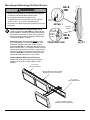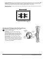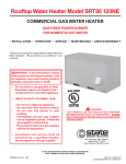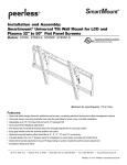
1
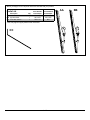
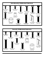
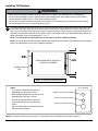
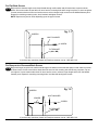
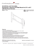
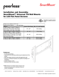
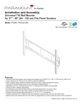
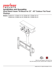
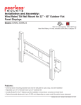
Installation and Assembly:
Universal Tilt Brackets for LCD and Plasma Flat Panel Screens
42''- 71'' (107 - 180 cm)
Models: ACC-DSV503, ACC-DSV503-P
Features:
• Universal tilt brackets easily hook onto wall plate for fast installation
• Adjustable up to 15° of forward tilt and up to -5° backward tilt for
optimal viewing angle
• One-touch tilt for effortless adjustment
• Pre-tensioned universal tilt bracket allows for tilt angle adjustment in
one easy motion.
• Easy grip handle locks the screen position into place
• Optional IncreLok feature offers fixed tilts at -5°, 0°, 5°, 10° and 15°
increments
• Includes Sorted-For-You™ fastener pack for installation to wood
studs, concrete, and cinder block
Accessories:
• DS-ACC-LDCM
cable management accessory (optional)
• DS-VL-H024 24" wall plate (optional)
• DS-VL-H036 36" wall plate (optional)
• DS-VL-H048 48" wall plate (optional)
• DS-VL-H060 60" wall plate (optional)
• DS-VL-H072 72" wall plate (optional)
Maximum Load Capacity: 250 lb (113 kg)
WARNING
• Do not begin to install your Peerless product until you have read and understood the instructions and warnings
contained in this Installation Sheet. If you have any questions regarding any of the instructions or warnings, for US
customers please call Peerless customer care at 1-800-865-2112, for all international customers, please contact
your local distributor.
• This product should only be installed by someone of good mechanical aptitude, has experience with basic building
construction, and fully understands these instructions.
• Make sure that the supporting surface will safely support the combined load of the equipment and all attached
hardware and components.
• Never exceed the Maximum Load Capacity. See page one.
• Always use an assistant or mechanical lifting equipment to safely lift and position equipment.
• Tighten screws firmly, but do not overtighten. Overtightening can damage the items, greatly reducing their holding
power.
• This product is intended for indoor use only. Use of this product outdoors could lead to product failure and personal
injury.
Note: Read entire instruction sheet before you start installation and assembly.
ISSUED: 06-04-10 SHEET #: 120-9081-2 05-14-12
Before you begin, be sure all parts shown are included with your product.
Parts List
AA
BB
CC
Description
lefttiltbracket
righttiltbracket
4mmallenwrench
Qty.
1
1
1
ACC-DSV503
ACC-DSV503-P
Part Number
Part Number
201-1474
201-1476
560-1131
AA
BB
201-1473
201-1475
N/A
Parts may appear slightly different than illustrated.
CC
2 of 7
ISSUED: 06-04-10 SHEET #: 120-9081-2 05-14-12
Non-Security Tilt Bracket Fasteners
M4 x 12mm (6)
(504-9013)
M5 x 12mm (4)
(520-1027)
M4 x 25mm (4)
(504-1015)
M6 x 12mm (4)
(520-1128)
M5 x 25mm (4)
(520-9543)
M6 x 20mm (4)
(520-9402)
M6 x 30mm (4)
(510-9109)
.5" spacer (4)
(540-1057)
M6 x 25mm (4)
(520-1208)
.75" spacer (4)
(540-1059)
M8 x 40mm (4)
(520-1136)
M8 x 16mm (6)
(520-9257)
multi-washer (6)
(580-1036)
M8 x 25mm (4)
(520-1031)
Security Tilt Bracket Fasteners
M4 x 12mm (6)
(510-1079)
M5 x 12mm (4)
(520-1064)
M4 x 25mm (4)
(510-1082)
M6 x 12mm (4)
(520-1050)
M5 x 25mm (4)
(520-1122)
M6 x 25mm (4)
(520-1211)
M8 x 15mm (6)
(520-1068)
.5" spacer (4)
(540-1057)
M6 x 20mm (4)
(520-9554)
multi-washer (6)
(580-1036)
M8 x 40mm (4)
(520-1152)
M6 x 30mm (4)
(520-1067)
M8 x 25mm (4)
(520-1101)
3 of 7
.75" spacer (4)
(540-1059)
ISSUED: 06-04-10 SHEET #: 120-9081-2 05-14-12
Installing Tilt Brackets
WARNING
• Tighten screws so adapter brackets are firmly attached. Do not tighten with excessive force. Overtightening
can cause stress damage to screws, greatly reducing their holding power and possibly causing screw heads to
become detached. Tighten to 40 in. • lb (4.5 N.M.) maximum torque.
• If screws don't get three complete turns in the screen inserts or if screws bottom out and bracket is still not tightly
secured, damage may occur to screen or product may fail.
1
To prevent scratching the screen, set a cloth on a flat, level surface that will support the weight of the screen. Place
screen face side down. Refer to screen manufacturers instructions or customer service, for removing any knobs,
base, cover or screw(s) on the back of the screen to prepare mounting. These need to be removed to allow the tilt
brackets to be attached. Select the small, medium, large or extra large screws from the baffled fastener pack then
attach tilt brackets to screen following figure 1.1 or 1.2.
Note: Top and bottom mounting holes on screen must be used for attaching brackets.
Note: Be sure to attach tilt brackets with handles facing outward as shown below. Verify that all holes are properly
aligned, and then tighten screws using a phillips screwdriver.
X
BB
AA
center brackets vertically on back of screen
handle face out
X
Note: "X" dimensions should be equal.
Notes:
multi-washer
• The number of fasteners used will vary,
depending upon the type of screen.
• Multi-washers and spacers may not be used,
depending upon the type of screen.
Medium hole for m5 SCrews
Small hole for m4 SCrews
• Use the corresponding hole in the multiwasher that matches your screw size as
shown.
• Slots in ST680 models are wider and require
the use of the M8 washer.
Large hole for m6 SCrews
NOTE: For flat back screens proceed to step 1-1. For bump-out or recessed back screen skip to step 1-2.
4 of 7
ISSUED: 06-04-10 SHEET #: 120-9081-2 05-14-12
For Flat Back Screen
1-1 Begin with the shortest length screw, hand thread through multi-washer and tilt bracket into screen as shown
below. Screw must make at least three full turns into the mounting hole and fit snug into place. Do not over tighten.
If screw cannot make three full turns into the screen, select a longer length screw from the baffled fastener pack.
Repeat for remaining mounting holes, level brackets and tighten screws.
NOTE: Spacers may not be used, depending upon the type of screen.
fig. 1.1
Screen
Multi-Washer
Screw
tilt Bracket
(AA or BB)
If you have any questions, please call Peerless customer care at 1-800-865-2112.
For Bump-out or Recessed Back Screen
1-2 Begin with longer length screw, hand thread through multi-washer, tilt bracket and spacer in that order into screen
as shown below. Screw must make at least three full turns into the mounting hole and fit snug into place. Do not
over tighten. If screw cannot make three full turns into the screen, select a longer length screw from the baffled
fastener pack. Repeat for remaining mounting holes, level brackets and tighten screws.
fig. 1.2
Screen
Multi-Washer
Spacer
Screw
Tilt Bracket
(AA or BB)
If you have any questions, please call Peerless customer care at 1-800-865-2112.
5 of 7
ISSUED: 06-04-10 SHEET #: 120-9081-2 05-14-12
Mounting and Removing Flat Panel Screen
AA &
BB
WARNING
• Always use an assistant or mechanical lifting equipment
to safely lift and position the flat panel screen.
• Do not tighten screws with excessive force.
Overtightening can cause damage to mount. Tighten
screws to 40 in. • lb (4.5 N.M.) maximum torque.
wall plate
• Be careful not to pinch fingers when pushing screen from
the bottom.
2
Tension Adjustment of Ratchet Handle: Adjust
tension in tilt brackets (AA & BB) by rotating ratchet
handle. NOTE: If obstruction prevents ratchet handle
from rotating, pull handle out while turning will allow
handle to reposition without tightening. Release and
turn handle to tighten or loosen.
Mounting Screen: Ratchet handle must be in the
up or down position or interference will occur while
hooking tilt brackets to wall plate. Slowly hook tilt
brackets (AA & BB) onto wall plate and swing screen
down as shown in fig. 2.1. Tilt bracket hooks must fully
engage wall plate as shown in detail 1. Using security
allen wrench (CC), turn safety/security screws on tilt
brackets (AA & BB) clockwise till screw tip securely
contacts wall plate as shown in cross section.
detail 1
Ratchet Handle
wall plate
safety/
security screw
AA &
BB
Cross section
fig. 2.1
Installing Multiple Wall Plates and Screens
Multiple wall plates (sold separately) and adapter
brackets can be used to create multiple screen
displays.
DS-VL-H024
(sold separately)
ADAPTER BRACKETS may appear different than illustrated
DS-VL-H048
(sold separately)
WALL PLATE may appear different than illustrated
6 of 7
ISSUED: 06-04-10 SHEET #: 120-9081-2 05-14-12
Screen Adjustment: Screen can be adjusted horizontally by loosening safety/security screws on tilt brackets (AA
& BB) three full turns. Adjust screen as shown in figure 2.2. Tighten safety/security screws on tilt brackets using
4 mm allen wrench (CC) till screw tip securely contacts wall plate as shown in cross section.
Removing Screen: To remove screen from mount, loosen safety screws, swing screen away from mount, and lift
screen off of mount.
WALL PLATE may appear different than illustrated
fig. 2.2
Adjusting the Tilt Angle of the Flat Panel Screen
3
For preset tilt angles use Increlok™ and for custom
tilt angle use ratchet handle.
IncreLok™
tilt locking
screw
INCRELOK™: The screen can be locked into a
pre-set tilt position of -5°, 0°, 5°, 10° or 15°. Use
locator hole to find tilt position hole and tilt screen to
align holes. Tighten IncreLok™ tilt locking screws on
both tilt brackets to lock tilt as shown in detail 2.
TILT
POSITION
HOLES
Ratchet Handle: Loosen ratchet handle (refer to
step 3 for tension adjustment of handle). Push or pull
from top or bottom of screen to adjust tilt as shown in
figure 3.1. The tilt can be adjusted to a maximum of
15° forward or 5° backward.
Locator hole
Ratchet Handle
detail 2
fig. 3.1
7 of 7
ISSUED: 06-04-10 SHEET #: 120-9081-2 05-14-12
© 2012, Peerless Industries, Inc. All rights reserved.
All other brand and product names are trademarks or registered trademarks of their respective owners.