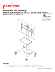
1
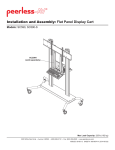
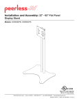
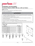
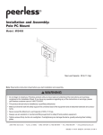
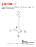
Installation and Assembly: 32" - 50" Flat Panel TV Stand
Models: SS550P, SS550P-S
R
This product is UL Listed. It must be
installed by a qualified professional
installer.
Max Load Capacity:
150 lb (68 kg) screen
50 lb (22.7 kg) per shelf
3215 W. North Ave. • Melrose Park, IL 60160 • (800) 729-0307 or (708) 865-8870 • Fax: (708) 865-2941 • www.peerlessmounts.com
ISSUED: 09-05-06 SHEET #: 202-9166-7 11-10-08
Note: Read entire instruction sheet before you start installation and assembly.
WARNING
• Do not begin to install your Peerless product until you have read and understood the instructions and warnings
contained in this Installation Sheet. If you have any questions regarding any of the instructions or warnings, please
call Peerless customer care at 1-800-865-2112.
• This product should only be installed by someone of good mechanical aptitude, has experience with basic building
construction, and fully understands these instructions.
• Make sure that the supporting surface will safely support the combined load of the equipment and all attached hardware and components.
• Never exceed the Maximum UL Load Capacity. See page one.
• If mounting to wood wall studs, make sure that mounting screws are anchored into the center of the studs. Use of an
"edge to edge" stud finder is highly recommended.
• Always use an assistant or mechanical lifting equipment to safely lift and position equipment.
• Tighten screws firmly, but do not overtighten. Overtightening can damage the items, greatly reducing their holding
power.
• This product was designed and intended to be mounted to the following supporting surfaces checked below with the
hardware included in this product as specified in the installation sheet. To mount this product to an alternative supporting surface, contact Peerless customer care at 1-800-865-2112.
• This product was designed to be installed on the following wall construction only;
WALL CONSTRUCTION
ADDITIONAL HARDWARE REQUIRED
x
x
x
x
None
None
None
None
Do not attach except with Peerless accessory kit for metal studs;
Contact Customer Service for Peerless accessory kit for metal studs.
Contact Customer Service
Contact Customer Service
Wood Stud
Wood Beam
Solid Concrete
Cinder Block
Metal Stud
Brick
Other or unsure?
Tools Needed for Assembly
• level
• phillips screwdriver
Table of Contents
Parts List .......................................................................................................................................................................... 3, 4
Assembling Floor Stand ........................................................................................................................................................ 4
Attaching Screen Using Universal Plate with Adapter Brackets ................................................................................................ 8
Attaching Screen with VESA 100 Mounting Pattern ............................................................................................................... 11
2 of 11
ISSUED: 09-05-06 SHEET #: 202-9166-7 11-10-08
A
B
Before you begin, make sure all parts shown are included with your product.
Parts List
A
B
C
D
E
F
G
H
I
J
K
L
M
N
O
P
Q
R
S
T
U
G
Description
screen mount bracket
hook plate
shelf support
shelf clamp bracket
base
universal plate
adapter bracket
upright
glass shelf
top cover
button bumper
1/4-20 x 12mm decorative screw
1/4-20 x 20mm decorative screw
1/4-20mm nut
5/16" flat washer
3/8-16 x 2.5" socket screw
7/32" allen wrench
4mm allen wrench
adhesive felt
M10 x15mm socket screw
6mm allen wrench
I
Qty.
1
1
2
2
1
1
2
1
2
1
18
18
4
18
14
3
1
1
1
4
1
J
SS550P
Black Part #
201-P1156
201-P1157
201-P1158
201-P1159
201-P1633
201-P1109
201-P1513
580-P1180
590-1208
590-1210
590-1209
520-2325
520-2326
530-1022
540-9406
520-9550
560-9715
560-9646
570-0043
520-9262
560-9716
K
SS550P-S
Silver Part#
201-4156
201-4157
201-4158
201-4159
201-4633
201-4109
200-4513
580-4180
590-1208
590-4210
590-1209
520-1325
520-1326
530-2022
540-9446
520-9550
560-9715
560-9646
570-0043
520-9262
560-9716
Q
R
H
D
E
F
L
M
P
C
N
T
O
S
U
Some parts may appear slightly different than illustrated.
3 of 11
ISSUED: 09-05-06 SHEET #: 202-9166-7 11-10-08
Phillips Adapter Bracket Fasteners
M4 x 12 mm (6)
504-9013
M4 x 25 mm (4)
504-1015
M5 x 12 mm (4)
520-1027
M6 x 30 mm (4)
510-9109
M6 x 12 mm (4)
520-1128
M6 x 25 mm (4)
520-1208
M8 x 16 mm (6)
520-9257
M6 x 20 mm (4)
520-9402
M8 x 25 mm (4)
520-1031
multi-washer (6)
580-1036
M8 x 40 mm (4)
520-1136
I.D. .22" (5.6 mm) (4)
540-1057
1
M5 x 25 mm (4)
520-9543
I.D. .34" (8.7 mm) (4)
540-1059
Cut adhesive felt (S) into four pieces as shown in figure 1.1 below and affix to bottom of base (E).
1-1 Attach upright (H) to base (E) using three 3/8-16 x 2.5" socket screws (P). Tighten screws using 7/32"
allen wrench (Q).
1-2 Run cords through upright (H) using cord management holes as shown in figure 1.2.
CORD MANAGEMENT HOLE
H
CORD MANAGEMENT HOLE
S
fig. 1.1
H
P
CORD MANAGEMENT HOLE
E
fig. 1.2
4 of 11
ISSUED: 09-05-06 SHEET #: 202-9166-7 11-10-08
2
Loosely attach four 1/4-20 x 12 mm screws (L),
washers (O), and 1/4-20 nuts (N) to shelf
support (C).
Slide shelf support (C) onto upright (H) so that 1/4-20
nuts (N) slide into slots of upright (H) as shown in figure
3 and detail 1. Slide shelf support to desired position,
level, then tighten 1/4-20 x 12 mm screws (L) using
4 mm allen wrench (R).
3
3-1 NOTE: MAXIMUM OF TWO SHELVES
Max height of top shelf is 34" from base.
Max height of second shelf is 28" from base.
N
L
C
O
L
N
C
SLOT
H
H
DETAIL 1
4
Insert six button bumpers (K) into shelf support (C).
Place glass shelf (I) on shelf support.
5
fig. 3
Insert three button bumpers (K) into bottom of shelf
clamp bracket (D).
5-1 Attach shelf clamp bracket (D) to shelf support (C)
using two 1/4-20 x 20 mm screws (M) and two
1/4-20 nuts (N).
5-2 For second shelf installation, repeat steps 2
through 5-1.
D
K
I
K
C
M
N
C
5 of 11
ISSUED: 09-05-06 SHEET #: 202-9166-7 11-10-08
6
Loosely attach six 1/4-20 x 12 mm screws (L),
washers (O), and 1/4-20 nuts (N) to screen mount
bracket (A).
Slide screen mount bracket (A) onto upright (H) so that
1/4-20 nuts (N) slide into slots of upright (H) as shown
in figure 7 and detail 2. Slide screen mount bracket to
desired position, level, then tighten 1/4-20 x 12 mm
screws (L) using 4 mm allen wrench (R).
7
N
A
N
L
SLOT
H
DETAIL 2
L
O
H
A
fig. 7
8
9
Snap top cover (J) onto upright (H).
Insert two 1/4-20 x 12 mm screws (L) into screen
mount bracket (A), leaving 1/8" of exposed thread as
shown in figure 9 and detail 3.
J
L
1/8"
A
H
DETAIL 3
fig. 9
6 of 11
ISSUED: 09-05-06 SHEET #: 202-9166-7 11-10-08
Attaching Screen Using Universal Plate with Adapter Brackets
For attaching screens with VESA 100 hole pattern, skip to page 10.
10
Attach universal plate (F) to hook plate (B) using four
M10 x 15 mm socket screws (T). Tighten screws
using 6 mm allen wrench (U).
11
Attach hook plate (B) to screen mount bracket (A).
B
F
B
T
12
A
Insert two 1/4-20 x 12 mm screws (L) into holes indicated below for desired screen orientation. Tighten all screws
using 4 mm allen wrench (R).
L
L
No Tilt
2° Backward Tilt
7 of 11
L
5° Forward Tilt
ISSUED: 09-05-06 SHEET #: 202-9166-7 11-10-08
Installing Adapter Brackets
WARNING
• Tighten screws so adapter brackets are firmly attached. Do not tighten with excessive force. Overtightening can cause
stress damage to screws, greatly reducing their holding power and possibly causing screw heads to become
detached. Tighten to 40 in. • lb (4.5 N.M.) maximum torque.
• If screws don't get three complete turns in the screen inserts or if screws bottom out and bracket is still not tightly
secured, damage may occur to screen or product may fail.
13
To prevent scratching the screen, set a cloth on a flat, level surface that will support the weight of the screen. Place screen
face side down. Refer to screen manufacturers instructions or customer service, for removing any knobs, base, cover, or
screw(s) on the back of the screen to prepare mounting. These need to be removed to allow the adapter brackets to be
attached. Select the small, medium, large or extra large screws from the baffled fastener pack then attach tilt brackets to
screen following figure 13.1 or 13.2.
NOTE: Top and bottom mounting holes must be used for attaching brackets. Verify that all holes are properly aligned, and
then tighten screws using a phillips screwdriver.
X
G
CENTER BRACKETS VERTICALLY
ON
BACK OF SCREEN
X
Note: "X" dimensions should be equal.
Notes:
MULTI-WASHER
• The number of fasteners used will vary,
depending upon the type of screen.
• Multi-washers and spacers may not be
used, depending upon the type of screen.
MEDIUM HOLE FOR M5 SCREWS
SMALL HOLE FOR M4 SCREWS
LARGE HOLE FOR M6 SCREWS
• Use the corresponding hole in the multiwasher that matches your screw size as
shown.
NOTE: For flat back screens proceed to step 13-1. For bump-out or recessed back screen skip to step 13-2.
8 of 11
ISSUED: 09-05-06 SHEET #: 202-9166-7 11-10-08
For Flat Back Screen
13-1
Refer to Screen Compatibility Chart to determine the proper fastener to use. Visit www.peerlessmounts.com/2
for a full screen compatibility chart for this mount.
Begin with the shortest length screw, hand thread through multi-washer and adapter bracket into screen as shown
below. Screw must make at least three full turns into the mounting hole and fit snug into place. Do not over tighten.
If screw cannot make three full turns into the screen, select a longer length screw from the baffled fastener pack.
Repeat for remaining mounting holes, level brackets and tighten screws.
NOTE: Spacers may not be used, depending upon the type of screen.
fig. 13.1
SCREEN
MULTI-WASHER
SCREW
ADAPTER
BRACKET (G)
If you have any questions, please call Peerless customer care at 1-800-865-2112.
For Bump-out or Recessed Back Screen
13-2 Refer to Screen Compatibility Chart to determine the proper fastener to use. Visit www.peerlessmounts.com/2
for a full screen compatibility chart for this mount.
Begin with longer length screw, hand thread through multi-washer, adapter bracket and spacer in that order into
screen as shown below. Screw must make at least three full turns into the mounting hole and fit snug into place.
Do not over tighten. If screw cannot make three full turns into the screen, select a longer length screw from the
baffled fastener pack. Repeat for remaining mounting holes, level brackets and tighten screws.
fig. 13.2
SCREEN
SPACER
MULTI-WASHER
SCREW
ADAPTER
BRACKET (G)
If you have any questions, please call Peerless customer care at 1-800-865-2112.
9 of 11
ISSUED: 09-05-06 SHEET #: 202-9166-7 11-10-08
Mounting and Removing Flat Panel Screen
WARNING
• Always use an assistant or mechanical lifting equipment to safely lift and position the plasma television.
14
Hook adapter brackets (G) onto universal plate (F), then slowly swing screen in as shown. Turn screws clockwise at
least six times to prevent screen from being removed as shown in detail 4.
Note: Tighten using 4 mm allen wrench (R).
Screen can be adjusted horizontally if desired.
Note: It is important to lock screen down! To lock the screen down, tighten screws to adapter bracket as shown in
detail 4.
To remove screen from mount, loosen screws, swing screen away from mount, and lift screen off of mount.
F
F
SCREWS
G
G
DETAIL 4
10 of 11
ISSUED: 09-05-06 SHEET #: 202-9166-7 11-10-08
Attaching Screen with VESA 100 Mounting Pattern
WARNING
• If screws don't get three complete turns in the screen inserts or if screws bottom out and hook plate is still not tightly
secured, damage may occur to screen or product may fail.
10
Choose hole pattern as shown in figure 10. Attach
hook plate (B) to back of screen using four M4 x 12
mm screws. Tighten screws using a phillips screwdriver.
11
Attach hook plate (B) to screen mount bracket (A).
B
fig 10
M4 X 12 MM SCREWS
12
A
B
Insert two 1/4-20 x 12 mm screws (L) into holes indicated below for desired screen orientation. Tighten all screws
using 4 mm allen wrench (R).
L
L
No Tilt
L
2° Backward Tilt
11 of 11
5° Forward Tilt
ISSUED: 09-05-06 SHEET #: 202-9166-7 11-10-08
© 2007, Peerless Industries, Inc. All rights reserved.
All other brand and product names are trademarks or registered trademarks of their respective owners.