1
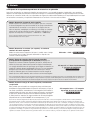
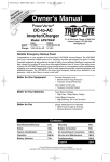
y r a ite ty nt ion y fo p L rran a t a rip a r ar strae tod EE T m/w W i lin FR .co g n te Re r o n a li Owner’s Manual i pp e ist to w .tri g w Re ce ww n ! a t ch uc od pr Sine Wave DC-to-AC Inverter/Chargers Models: APS1012SW, APS2012SW 12VDC to 120VAC Table of Contents Important Safety Instructions 1. Overview & Features 1.1 Overview 1.2 Indicators, Controls and Settings 1.3 Optional Features 2. Battery Charger 2.1 Mode of Operation 2.2 Transfer Switching Speed 3. Battery Installation and Maintenance 3.1 Select Battery Type 3.2 Monthly Maintenance 3.3 Battery Installation 3.4 Battery Connection 2 3 3 3 6 6 6 6 4. Inverter/Charger Installation and Operation 10 4.1 Installation 10 4.2 Installation Diagrams and Charts 10 4.3 Installation and Start-Up 11 5. Technical Specifications 11 6. Troubleshooting 12 7. Service and Warranty Registration 12 Español13 6 6 8 8 8 1111 W. 35th Street, Chicago, IL 60609 USA www.tripplite.com/support Copyright © 2011 Tripp Lite. All rights reserved. 1 Important Safety Instructions SAVE THESE INSTRUCTIONS! This manual contains important instructions and warnings that should be followed during the installation, operation and storage of all Tripp Lite Inverter/Chargers. Location Warnings • Install your Inverter/Charger in a location or compartment that minimizes exposure to heat, dust, direct sunlight and moisture. Flooding the unit with water will cause it to short circuit and could cause personal injury due to electric shock. • Leave a minimum of 2” clearance at front and back of the Inverter/Charger for proper ventilation. To avoid overheating the Inverter, any compartment that contains the Inverter/Charger must be properly ventilated with adequate outside air flow. The heavier the load of connected equipment, the more heat will be generated by the unit. • Do not install the Inverter/Charger directly near magnetic storage media, as this may result in data corruption. • Do not install near flammable materials, fuel or chemicals. • Do not mount unit with its front or rear panel facing down (at any angle). Mounting in this manner will seriously inhibit the unit’s internal cooling, eventually causing product damage not covered under warranty. Battery Connection Warnings • Multiple battery systems must be comprised of batteries of identical voltage, age, amp-hour capacity and type. • Because explosive hydrogen gas can accumulate near batteries if they are not kept well-ventilated, do not install batteries in a “dead air” compartment. Ideally, any compartment would have some ventilation to outside air. • Sparks may result during final battery connection. Always observe proper polarity as batteries are connected. • Do not allow objects to contact the DC input terminals. Do not short or bridge these terminals together. Serious personal injury or property damage could result. Ground Connection Warnings • Safe operation requires connecting the Inverter/Charger’s Main Ground Terminal directly to the frame of the vehicle or earth ground. Equipment Connection Warnings • Use of this equipment in life support applications where failure of this equipment can reasonably be expected to cause the failure of the life support equipment or to significantly affect its safety or effectiveness is not recommended. Do not use this equipment in the presence of a flammable anesthetic mixture with air, oxygen or nitrous oxide. • You may experience uneven performance results if you connect a surge suppressor, line conditioner or UPS system to the output of the Inverter/Charger. •User must supply proper protection for wire openings in unit panels. Operation Warnings • Your Inverter does not require routine maintenance. • Potentially lethal voltages exist within the Inverter/Charger as long as the battery supply is connected. During any service work, the battery supply should therefore be disconnected. • Do not connect or disconnect batteries while the Inverter/Charger is operating from the battery supply. Dangerous arcing may result. 2 1. Overview and Features 1.1 Overview • Tripp Lite’s Sine Wave Inverter-Charger is a heavy-duty unit generating a pure sine wave from a 12V battery bank. It can supply energy to a wide range of connected equipment; from heaters, air conditioners, refrigerators and vacuum cleaners to computers and peripheral devices. It is designed to work in heavy load conditions, so de-rating is unnecessary. • The smart charger is compatible with various battery types and sizes. The switch module automatically diverts the energy transfer path between the inverter and an AC input. When the AC source is lower than the transfer level, the path switches to the inverter. Otherwise, the load is powered by the AC input. 1.2 Indicators, Controls and Settings 1.2.1 Controls and LED Indicators Shown below are the control panel and indicator lights on the front panel of the Inverter/Charger. 1 2 3 4 5 6 7 10 8 9 11 1 Power ON/OFF Button 5 LED 4 – Battery Limits 9 LED 8 – 100% Battery Voltage 2 LED 1 – DC Mode Inverter 6 LED 5 – 25% Battery Voltage 10 Battery Temperature Port (RJ11) 3 LED 2 – AC Mode Charger 7 LED 6 – 50% Battery Voltage 11 Communication Port (RJ45) 4 LED 3 – Inverter Condition 8 LED 7 – 75% Battery Voltage 3 1. Overview and Features LED and Alarm Indicator LED 1 LED 2 LED 3 LED 4 LED 5 LED 6 LED 7 On/ Off Off 10.8V~11.5V 11.5 ~ 12.5V 12.5 ~ 13.5V Flashing Off Off Off 10.2 ~ 11.5V 11.5 ~ 12.5V 12.5 ~ 13.0V LED 8 Alarm >13.5V Off AC Normal Off DC Mode On Battery Low (DC Mode) On Off Off On Off Off Off On On Off Off On Off On Off 10.2 ~ 11.5V 11.5 ~ 12.5V 12.5 ~ 13.0V >13.0V 1 beep @ 0.5 sec On Off On Off 10.2 ~ 11.5V 11.5 ~ 12.5V 12.5 ~ 13.0V >13.0V On (Constant) On Off On Off 10.2 ~ 11.5V 11.5 ~ 12.5V 12.5 ~ 13.0V >13.0V On (Constant) Off Off Off Off 10.8 ~ 11.5V 11.5 ~ 12.5V 12.5 ~ 13.5V >13.5V Off Low Battery Cutoff (LBCO) Battery High (AC Mode) Overload— 110%-129% (DC Mode) Overload— 130%-149% (DC Mode) Overload— >150% (DC Mode) AC Bypass Power Off 10.2 ~ 11.5V 11.5 ~ 12.5V 12.5 ~ 13.0V Off Off Off Flashing 10.2 ~ 11.5V 11.5 ~ 12.5V 12.5 ~ 13.0V >13.0V Off 1 beep >13.0V @ 5 sec for 3 min. 1 beep @ Off shutdown 1 beep >13.0V @ 0.5sec 1.2.2 Power ON/OFF Button The Power ON/OFF button is located in the left of the panel. Press to power the Inverter/Charger ON or OFF. When the button is pressed, the alarm will beep. Note: When connected to batteries, the Inverter/Charger will start up even if not connected to AC power. Defaults to 60Hz. Note: Unit is in BYPASS mode as soon as power is applied to the input. Power On: Press the Power ON/OFF button for 3 seconds until the alarm beeps and the INVERTER MODE light illuminates. Power Off: Press the Power ON/OFF button for 3 seconds. The alarm will beep when the shutdown process is completed. 1.2.3 DC Mode Inverter (LED 1) This LED illuminates to indicate that the system is working in inverter mode (supplying power from battery). 1.2.4 AC Mode Charger (LED 2) The LED flashes during the charging process and remains illuminated once the battery is full charged. 1.2.5 Inverter Condition (LED 3) When the inverter temperature exceeds the default setting, this LED will flash and the inverter will shut down automatically. After the temperature returns to normal, depress the Power ON/OFF button to restart. When the unit is overloaded in DC mode, LEDs 1, 3 and the audible alarm indicate inverter status as follows: Load Capacity (DC Mode) LED1 LED 3 Alarm INVERTER STATUS 110%-129% On On 1 beep/0.5sec Shutdown after 60 seconds. 130%-149% On On On (Constant) Shutdown after 10 seconds. >150% On On On (Constant) Shutdown after 1 second. 1.2.6 Battery Limits (LED 4) Battery High: In AC mode, LED 4 will flash. Battery Low: LED 4 will illuminate and the alarm will beep once every five seconds for three minutes. If the battery voltage drops below the cutoff voltage (LBCO), then the inverter will shut down all LEDs except LED4, and will turn off. 4 1. Overview and Features 1.2.7 Battery Voltage (LED 5-8) LED 5-8 indicate the battery capacity as detailed in the following table: Battery Voltage 25% 50% 75% 100% LED 5 On On On On LED 6 — On On On LED 7 — — On On LED 8 — — — On 1.2.8 Voltage Setting (Switch 1-3)* Switch DC-to-AC Transfer Delay (Switch 1) Low Battery Alarm (Switch 2) AC Transfer Voltage (Switch 3) ON 30 sec (Default) 11.2V 95V OFF 5 sec 10.9V (Default) 85V (Default) *Note: 1. Switch 1 is located farthest from the battery temperature port. See diagram on page 3. 2. All switches must be set before the system is turned on. 3. Switch 2 sets the low battery voltage alarm level (at higher voltage, the alarm sounds sooner). 4. Switch 3: Low-level AC-to-DC voltage point. If the AC input voltage decreases to below the setpoint, the inverter will automatically switch to DC MODE. Please see the table for details. Nominal Voltage On 120V Off Low Voltage Transfer Point (AC-to-DC) 95 85 Return Voltage Point (DC-to-AC) 100 90 1.2.9 Search Mode Setting (Switch 4) Search Mode activates when the unit is operating in inverter mode (battery power) to prevent unnecessary battery discharge when electrical power is not required. If the inverter is supporting loads that must constantly be powered, turn off switch 4 to disable Search Mode. Switch 4 ON Search Mode Enable OFF (Default) Disable Function Inverter only turns on if load > 100W Inverter is always on in the absence of AC power 1.2.10 Battery Type/Floating Voltage (Switch 5) Switch 5 ON (Default) OFF Floating Voltage 13.8V 13.2V Acceptance Voltage 14.5V 13.8V Battery Type Absorbed Glass Mat (AGM) Wet-Cell Note: The unit will charge the battery to Acceptance voltage, continue for up to 12 hours, then drop to Floating voltage. 5 1. Overview and Features 1.2.11 Battery Charging Rate Setting (Switch 6, 7 & 8) These switches control the maximum charging rate in amps. The charge rate has 8 stages. It can be adjusted by setting these switches as shown in the following table: Switch 6 ON ON ON ON OFF OFF OFF OFF Switch 7 ON ON OFF OFF ON ON OFF OFF Switch 8 ON OFF ON OFF ON OFF ON OFF APS1012SW 40A 32A 24A 20A (Default) 16A 12A 8A 4A APS2012SW 60A 48A 36A 30A (Default) 24A 18A 12A 6A Note: The charging rate depends on the battery bank size. Consult the battery manufacturer’s specs for the maximum allowed charge rate (usually 0.3 times the AH rating). Caution! An excessively high charging rate can overheat the battery. If a small-capacity battery is used, set the battery charge rate to the minimum setting. 1.3 Features 1.3.1 Battery Temperature Port This port allows connection of a Battery Temperature-Sensing Cable (sold separately). The sensing function prolongs battery life by adjusting the charge float voltage level based on battery temperature. Connect the sensor cable to the RJ11 port labeled “Battery Temperature.” With user-supplied electrical or duct tape, secure the sensor to the side of the battery below the electrolyte level. Make sure that nothing, not even tape, comes between the sensor and the side of the battery. To guard against false readings due to ambient temperature, place the sensor between batteries, if possible, or away from the sources of extreme heat or cold. If the sensor cable is not used, the Inverter/Charger will charge according to its default 25°C values. 1.3.2 Communication Port (for APSRMSW Remote Control) This port allows connection with the APSRMSW Remote Control (sold separately). The remote conrol allows the Inverter/ Charger to be mounted in a compartment or cabinet out of sight, while operated conveniently from a remote location. See instructions packed with the remote control module for more information. 2. Battery Charger 2.1 Mode of Operation The internal battery charger and automatic transfer relay allow the unit to operate as either a battery charger or an inverter. An external source of AC power (e.g., shore power or generator) must be supplied to the inverter’s AC input in order to allow it to operate as a battery charger. When the unit is operating as a charger, AC loads are powered by the external AC power source. 2.2 Transfer Switching Speed Transfer time is less than 16 milliseconds. 3. Battery 3.1 Select Battery Type Select 12V “Deep Cycle” batteries to receive optimum performance from your Inverter/Charger. Do not use ordinary car or starting batteries or batteries rated in Cold Cranking Amps (CCA). If the batteries you connect to the Inverter/Charger are not true Deep Cycle batteries, their operational lifetimes may be significantly shortened. If you are using the same battery bank to power the Inverter/Charger as well as DC loads, your battery bank will need to be appropriately sized (larger loads will require a battery bank with a larger amp-hour capacity) or the operational lifetimes of the batteries may be significantly shortened. Batteries of either Wet-Cell (vented) or Gel-Cell /Absorbed Glass Mat (sealed) construction are ideal. Set Switch 5 to OFF for Wet-Cell batteries and to ON for Absorbed Glass Mat (AGM) batteries. Two 6-volt “golf cart”, Marine Deep-Cycle or 8D Deep-Cycle batteries in series are also acceptable. In many cases, the vehicle battery may be the only one installed. Auxiliary batteries must be identical to the vehicle batteries if they are connected to each other. 6 3. Battery 3.1.1 Match Battery Amp-Hour Capacity to Your Application Select a battery or system of batteries that will provide your Inverter/Charger with proper DC voltage and an adequate amphour capacity to power your application. Even though Tripp Lite Inverter/Chargers are highly-efficient at DC-to-AC inversion, their rated output capacities are limited by the total amp-hour capacity of connected batteries and the support of your vehicle’s alternator if the engine is kept running. Example •STEP 1: Determine Total Wattage Required Add the wattage ratings of all equipment you will connect to your Inverter/Charger. Wattage ratings are usually listed in equipment manuals or on nameplates. If your equipment is rated in amps, multiply that number times AC utility voltage to determine watts. (Example: a ¼ in. drill requires 2½ amps. 2½ amps × 120 volts = 300 watts .) Note: Your Inverter/Charger will operate at higher efficiencies at about 75% - 80% of nameplate rating. •STEP 2: Determine DC Battery Amps Required Divide the total wattage required (from step 1, above) by the battery voltage (12) to determine the DC amps required. •STEP 3: Estimate Battery Amp-Hours Required (for operation unsupported by the alternator) Multiply the DC amps required (from step 2, above) by the number of hours you estimate you will operate your equipment exclusively from battery power before you have to recharge your batteries with utility- or generator-supplied AC power. Compensate for inefficiency by multiplying this number by 1.2. This will give you a rough estimate of how many amp-hours of battery power (from one or several batteries) you should connect to your Inverter/Charger. Tools ¼” Drill 300W Blender 300W Orbital Sander Cordless Tool Charger + 220W + 20W = 540W Appliances Color TV + 140W Laptop Computer + 100W = 540W 540 watts ÷ 12V = 45 DC Amps 45 DC Amps × 5 Hrs. Runtime × 1.2 Inefficiency Rating = 270 Amp-Hours NOTE! Battery amp-hour ratings are usually given for a 20-hour discharge rate. Actual amp-hour capacities are less when batteries are discharged at faster rates. For example, batteries discharged in 55 minutes provide only 50% of their listed amphour ratings, while batteries discharged in 9 minutes provide as little as 30% of their amp-hour ratings. •STEP 4: Estimate Battery Recharge Required, Given Your Application You must allow your batteries to recharge long enough to replace the charge lost during inverter operation or else you will eventually run down your batteries. To estimate the minimum amount of time you need to recharge your batteries given your application, divide your required battery amp-hours (from step 3, above) by your Inverter/ Charger’s rated charging amps (depending on the Switch 6, 7 and 8 ON/OFF settings). NOTE! For Tripp Lite Inverter/Chargers providing 1000 watts or less of continuous AC power, a full-size battery will normally allow sufficient power for many applications before recharging is necessary. For mobile applications, if a single battery is continuously fed by an alternator at high idle or faster, then recharging from utility or generator power may not be necessary. For Tripp Lite Inverter/Chargers over 1000 watts used in mobile applications, Tripp Lite recommends you use at least two batteries, if possible fed by a heavy-duty alternator anytime the vehicle is running. Tripp Lite Inverter/ Chargers will provide adequate power for ordinary usage within limited times without the assistance of utility or generator power. However, when operating extremely heavy electrical loads at their peak in the absence of utility power, you may wish to “assist your batteries” by running an auxiliary generator or vehicle engine, and doing so at faster than normal idling. 7 270 Amp-Hours ÷ 55 Amps Inverter/Charger Rating = 5 Hours Recharge 3. Battery 3.2 Monthly Maintenance • Check the level of the electrolyte of each Wet-Cell battery cell monthly after the batteries have been charged. It should be about one-half inch above the top of the plates, but not completely full. Note: This is not necessary on maintenance-free batteries. • Check the battery connections for tightness and corrosion. If any corrosion is found, disconnect the cables and clean them with a mild solution of baking soda and water. DO NOT ALLOW THE SOLUTION TO ENTER THE BATTERY. When finished, rinse the top of the battery with clean water. • To reduce corrosion on the battery terminals, coat them with a thin layer of petroleum jelly or anti-corrosion grease. Do not apply any material between the terminal and the cable lugs; the connection should be metal to metal. Apply the protective material after the bolts have been tightened. 3.3 Battery Installation Caution! Batteries can produce extremely high currents. Review both the important safety instructions at the beginning of this manual and the battery supplier’s precautions before installing the inverter and batteries. 3.3.1 Battery Location Batteries should be installed in an accessible location with good access to the battery caps and terminals. At least two feet (24 in.) of overhead clearance is recommended. They must be located as close as possible to the inverter. Do not locate the inverter in the same compartment with non-sealed batteries (sealed batteries are acceptable). The gasses produced by these batteries during charging are very corrosive and will shorten the life of the inverter. 3.3.2 Battery Enclosure Batteries should be installed in a ventilated, locked enclosure or room. The enclosure should be well-ventilated to prevent accumulation of hydrogen gasses that are released in the battery charging process. The enclosure should be made of acid resistant material or coated with an acid resistant finish to resist corrosion from spilled electrolyte and released fumes. If the batteries are located outdoors, the enclosure should be rainproof and have mesh screens to prevent insects and rodents from entering. Before placing the batteries in the enclosure, cover the bottom with a layer of baking soda to neutralize any acid spills. 3.4 Battery Connection 3.4.1 Connect your Inverter/Charger to your batteries using the following procedures: • Connect DC Wiring: Though your Inverter/Charger is a high-efficiency converter of electricity, its rated output capacity is limited by the length and gauge of the cabling running from the battery to the unit. Use the shortest length and largest diameter cabling to provide maximum performance (see table below). Shorter and heavier gauge cabling reduces DC voltage drop and allows for maximum transfer of current. Your Inverter/Charger is capable of delivering peak wattage at up to 200% of its rated continuous wattage output for brief periods of time. Heavier gauge cabling should be used when continuously operating heavy draw equipment under these conditions. Tighten your Inverter/Charger and battery terminals to approximately 3.5 Newton-meters of torque to create an efficient connection and to prevent excessive heating at this connection. Insufficient tightening of the terminals could void your warranty. Maximum Recommended DC Cable Length Maximum Distance From Battery to Inverter/ Charger Wire Gauge (AWG) Output 2 0 00 (2/0) 1000W 20 ft. 31 ft. 39 ft. 2000W Do not use Do not use 20 ft. 8 3. Battery • Connect Fuse: NEC (National Electrical Code) article 551 requires that you connect all of your Inverter/Charger’s positive DC Terminals directly to a UL-listed fuse(s) and fuse block(s) within 18 inches of the battery. The fuse’s rating must equal or exceed the minimum DC fuse rating displayed on the Inverter/Charger’s nameplate. See diagrams below for proper fuse placement. WARNING! • Failure to properly ground your Inverter/Charger to a vehicle’s chassis or earth ground may result in a lethal electrical shock hazard. • Never attempt to operate your Inverter/Charger by connecting it directly to output from an alternator rather than a battery or battery bank. • Observe proper polarity with all DC connections. 3.4.2 Non-Vehicular or Vehicular Your Inverter/Charger’s Nominal DC Input Voltage must match the voltage of your battery or batteries—12 Volts in most vehicular applications. It is possible to connect your Inverter/Charger to the main battery within your vehicle’s electrical system. In most vehicles, the Inverter/ Charger will be connected to one or more dedicated auxiliary (house) batteries that are isolated from the drive system to prevent possible draining of the main battery. 3 1 7 2 12 Volts 12 Volt Inverter/Charger 12 Volts 5 12 Volt Main Battery Connection 7 4 1 6 2 12 Volts 12 Volt Inverter/Charger 3 12 Volts 2 5 12 Volts 12 Volt Main and Auxiliary (House) Battery Connection (Isolated Parallel) 1 12 Volt Alternator 2 Vehicle Battery Ground 3 12 Volt Main Battery 4 12 Volt Auxiliary (House) Battery 5 UL-Listed Fuse & Fuse Block (mounted within 18 inches of the battery) 6 Battery Isolator 7 Large Diameter Cabling, Maximum 2/0 Gauge to Fit Terminals 9 4. Installation and Operation 4.1 Installation 4.1.1 Environment The Inverter/Charger must be installed in a protected location that is isolated from sources of high temperature and moisture. To promote peak performance, battery cables should be kept as short as possible. However, do not install the Inverter/Charger in the same compartment as non-sealed batteries. Accumulated hydrogen and oxygen generated by the batteries could be ignited by an arc (resulting from connection of the battery cables) or by switching a relay. The Inverter/Charger requires unrestricted air flow to operate at high power for sustained periods. Do not mount the inverter in an enclosed space. This will restrict air flow and cause the inverter’s protection circuitry will activate, reducing maximum available power. 4.1.2 System Grounding Proper grounding is essential to assure safe operation of the Inverter/Charger. Grounding requirements vary in country and application. For specific requirements pertaining to your location and application, consult local codes and the NEC. 4.2 Installation Diagrams and Charts 4.2.1 Terminal Block (AC Side) 4.2.2 Terminal (DC Side)4. Installation and Operation 10 4. Installation and Operation 4.3 Installation and Start-Up 4.3.1 Connect the unit to the batteries per Section 3. Ensure that the nominal DC battery voltage is 12V. 4.3.2 Connect the unit to the AC load. Then, connect to the AC source. Confirm all wiring is correct and terminal is tight. 4.3.3 Press the ON/OFF button. The system will start working after a few seconds. If the AC source power fails, the unit will work in Inverter mode. Otherwise, the system will switch to AC Mode and will power the load while charging the battery. 5. Technical Specifications Model Specification Continuous Power Peak Inverter Efficiency Output Waveform DC Current at Rated Power Recommended Battery Fuse Nominal Input Voltage DC Input Voltage Range Low Battery Protection (Heavy/Light Load) DC Mode Output Voltage Regulation Power Factor Allowed Frequency Regulation Standard Output Voltage Load Sensing (Power Saving) Transfer Time Forced Air Cooling Automatic Transfer Relay Adjustable Charge current Resistive Load Inductive Load Motor Load APS1012SW APS2012SW 1000 Watts 2000 Watts >79% Sine Wave 120 Amps 200 Amps 250 Amps 400 Amps 12 VDC 10.0 ~ 16 VDC 10.9/11.2 VDC +/- 10% 0.8 to 1 50/60 Hz +/- 0.5 Hz (Autoselect) 120 VAC 100 W 16 ms, maximum Variable Speed 15A 30A 4 ~ 40 A 6 ~ 60A 100% YES YES Rectifier Load YES Wall-Mounting YES 11 6. Troubleshooting • Your Inverter/Charger requires no maintenance and contains no user-serviceable or user-replaceable parts, but should be kept dry at all times. Periodically check, clean and tighten all cable connections, as necessary, both at the unit and at the battery. • A small-size battery being charged at a higher charging rate could cause an overvoltage shutdown. To prevent this, reduce the charge rate or discharge the battery before recharging. • If the Inverter does not start up properly, disconnect the system from the battery for 30 seconds, and then repeat the startup procedure. If the system still does not start up properly, visit www.tripplite.com/support. 7. Service Your Tripp Lite product is covered by the warranty described in this manual. A variety of Extended Warranty and On-Site Service Programs are also available from Tripp Lite. For more information on service, visit www.tripplite.com/support. Before returning your product for service, follow these steps: 1. Review the installation and operation procedures in this manual to insure that the service problem does not originate from a misreading of the instructions. 2. If the problem continues, do not contact or return the product to the dealer. Instead, visit www.tripplite.com/support. 3. If the problem requires service, visit www.tripplite.com/support and click the Product Returns link. From here you can request a Returned Material Authorization (RMA) number, which is required for service. This simple on-line form will ask for your unit’s model and serial numbers, along with other general purchaser information. The RMA number, along with shipping instructions will be emailed to you. Any damages (direct, indirect, special or consequential) to the product incurred during shipment to Tripp Lite or an authorized Tripp Lite service center is not covered under warranty. Products shipped to Tripp Lite or an authorized Tripp Lite service center must have transportation charges prepaid. Mark the RMA number on the outside of the package. If the product is within its warranty period, enclose a copy of your sales receipt. Return the product for service using an insured carrier to the address given to you when you request the RMA. WARRANTY REGISTRATION Visit www.tripplite.com/warranty today to register the warranty for your new Tripp Lite product. You’ll be automatically entered into a drawing for a chance to win a FREE Tripp Lite product!* * No purchase necessary. Void where prohibited. Some restrictions apply. See website for details. Regulatory Compliance Identification Numbers For the purpose of regulatory compliance certifications and identification, your Tripp Lite product has been assigned a unique series number. The series number can be found on the product nameplate label, along with all required approval markings and information. When requesting compliance information for this product, always refer to the series number. The series number should not be confused with the marking name or model number of the product. Tripp Lite follows a policy of continuous improvement. Product specifications are subject to change without notice. 1111 W. 35th Street, Chicago, IL 60609 USA www.tripplite.com/support 12 201110125 • 933053-EN Manual del propietario Convertidores /cargadores de ondas sinusoidales CC a CA Modelos: APS1012SW, APS2012SW 12V CC a 120V CA Índice Instrucciones de seguridad importantes14 1. Visión de conjunto y características 15 1.1 Visión de conjunto 15 1.2 Indicadores, controles y configuraciones 15 1.3 Características opcionales 18 2. Cargador de batería 18 2.1 Modo de funcionamiento 18 2.2 Velocidad de transferencia de conexión 18 3. Instalación y mantenimiento de la batería 18 3.1 Seleccionar el tipo de batería 18 3.2 Mantenimiento mensual 20 3.3 Instalación de la batería 20 3.4 Conexión de la batería 20 4. Convertidor/cargador Instalación y funcionamiento 22 4.1 Instalación 22 4.2 Diagramas y gráficos de instalación 22 4.3 Instalación y puesta en marcha 23 5. Especificaciones técnicas 23 6. Solución de problemas 24 7. Asistencia técnica y registro de la garantía 24 English1 1111 W. 35th Street, Chicago, IL 60609 USA www.tripplite.com/support Copyright © 2011 Tripp Lite. Todos los derechos reservados. 13 Instrucciones de seguridad importantes ¡GUARDE ESTAS INSTRUCCIONES! Este manual contiene instrucciones y advertencias importantes que se deben seguir durante la instalación, el funcionamiento y el almacenaje de todos los convertidores/cargadores Tripp Lite. Advertencias de ubicación • Instale su convertidor/cargador en una ubicación o compartimento que minimice la exposición al calor, polvo, luz solar directa y humedad. Si la unidad se llena de agua se puede producir un cortocircuito que podría causar lesiones físicas debido a una descarga eléctrica. • Deje un espacio mínimo de 2 pulgadas (5 cm) en la parte delantera y trasera del convertidor/cargador para una adecuada ventilación. Con el fin de evitar el sobrecalentamiento del convertidor, cualquier compartimento en el que esté alojado el dispositivo debe estar adecuadamente ventilado con una entrada de aire del exterior. Cuanto más pesada sea la carga del equipo conectado, más calor generará la unidad. • No instale el convertidor/cargador directamente cerca de un medio de almacenaje magnético, ya que esto puede corromper los datos. • No realice la instalación cerca de materiales inflamables, combustibles ni productos químicos. • No monte esta unidad con el panel frontal o con el panel trasero hacia abajo (Bajo ningún ángulo o inclinación). Si lo monta de esta manera, inhibirá seriamente el sistema de enfriamiento interno de la unidad; lo que finalmente causará daños al producto que no están cubiertos por la garantía. Advertencias de conexión de la batería • Los sistemas de varias baterías pueden estar compuestos de baterías de idéntico voltaje, antigüedad, capacidad amperiohora y tipo. • Como se puede acumular hidrógeno explosivo cerca de las baterías si no están bien ventiladas, no debe instalar estas en un compartimento con aire viciado. Lo ideal es que cualquier compartimento disponga de una entrada de aire exterior para la ventilación. • Se pueden producir chispas durante la conexión de la batería. Al conectar las baterías, hágalo siempre en los polos adecuados. • No permita que haya objetos en contacto con los terminales de entrada CC. No acople ni conecte estos terminales juntos. Se pueden producir daños a la propiedad o lesiones físicas graves. Advertencias de conexión a tierra • Una operación segura requiere conectar la terminal de conexión a tierra del Inversor/Cargador directamente al bastidor del vehículo o una tierra física. Advertencias de conexión del equipo • El uso de este equipo en aplicaciones de soporte de vida en donde la falla de este equipo pueda razonablemente hacer suponer que causará fallas en el equipo de soporte de vida o afecte significativamente su seguridad o efectividad, no está recomendado. No use este equipo en la presencia de una mezcla anestésica inflamable con aire, oxigeno u óxido nitroso. • Podrá experimentar resultados de rendimiento desigual si conecta un supresor de sobrecarga, un acondicionador de línea o un sistema UPS a la toma de salida del convertidor/cargador. •El usuario debe suministrar la protección adecuada para las aberturas de paso de cables en los paneles de la unidad. Advertencias de funcionamiento • Su convertidor no requiere mantenimiento rutinario. • En el interior del convertidor/cargador puede haber voltajes potencialmente peligrosos mientras el suministro de la batería esté conectado. Por lo tanto, durante cualquier trabajo de mantenimiento, la batería debe estar desconectada. • No conecte ni desconecte las baterías mientras el convertidor/cargador está funcionando con suministro de la batería. Se puede producir un arco eléctrico peligroso. 14 1. Visión de conjunto y características 1.1 Visión de conjunto • El convertidor/cargador de ondas sinusoidales de Tripp Lite es una unidad de carga de gran potencia que genera una onda sinusoidal pura a partir de un módulo de baterías de 12V. Puede suministrar energía a gran variedad de equipos conectados: desde radiadores, aparatos de aire acondicionado, refrigeradores y aspiradoras a ordenadores y dispositivos periféricos. Está diseñado para trabajar en condiciones de carga pesada, de manera que no es necesaria una disminución de potencia. • El cargador inteligente es compatible con varios tipos y tamaños de baterías. El módulo del conmutador desvía automáticamente la trayectoria de transferencia de energía entre el convertidor y una entrada de CA. Cuando la fuente de CA es menor que el nivel transferido, la trayectoria pasa al convertidor. De otro modo, la carga se alimenta por medio de la entrada de CA. 1.2 Indicadores, controles y configuraciones 1.2.1 Controles e indicadores LED Abajo se muestra el panel de control y las luces indicadoras del panel frontal del convertidor/cargador. 1 2 3 4 5 6 7 10 1 Botón POWER ON/OFF de encendido y apagado 2 LED 1 – Convertidor en modo CC 3 LED 2 – Cargador en modo CA 4 LED 3 – Estado del convertidor 8 9 11 5 LED 4 – Límites de batería 9 LED 8 – 100% de voltaje de batería 6 LED 5 – 25% de voltaje de batería 10 Puerto de temperatura de la batería 7 LED 6 – 50% de voltaje de batería 8 LED 7 – 75% de voltaje de batería 15 (RJ11) 11 Puerto de comunicación (RJ45) 1. Visión de conjunto y características LED e indicador de alarmas LED 1 LED 2 LED 3 On/ Off Flashing*** LED 4 CA Normal Off* Modo CD On** Off Off Off On Off Off On Off Off Off On On Off Off Flashing On Off On Off On Off On Off On Off On Off Off Off Off Off Batería Baja (Modo CD) Corte por Batería Baja (LBCO) Batería Alta (Modo CA) Sobrecarga— 110%-129% (Modo CD) Sobrecarga— 130%-149% (Modo CD) Sobrecarga— >150% (Modo CD) Rodeo CA Apagado Off LED 5 10.8V~ 11.5V 10.2 ~ 11.5V 10.2 ~ 11.5V LED 6 11.5 ~ 12.5V 11.5 ~ 12.5V 11.5 ~ 12.5V LED 7 12.5 ~ 13.5V 12.5 ~ 13.0V 12.5 ~ 13.0V Off Off Off 10.2 ~ 11.5V 10.2 ~ 11.5V 10.2 ~ 11.5V 10.2 ~ 11.5V 10.8 ~ 11.5V 11.5 ~ 12.5V 11.5 ~ 12.5V 11.5 ~ 12.5V 11.5 ~ 12.5V 11.5 ~ 12.5V 12.5 ~ 13.0V 12.5 ~ 13.0V 12.5 ~ 13.0V 12.5 ~ 13.0V 12.5 ~ 13.5V LED 8 Alarma >13.5V Apagado >13.0V Apagado >13.0V 1 bip @ 5 seg. por 3 min. Off 1 bip @apagado >13.0V 1 bip @ 0.5 seg. >13.0V 1 bip @ 0.5 seg. >13.0V >13.0V >13.5V Encendido (Constante) Encendido (Constante) Apagado *Apagado **Encendido ***Encendido/ Destellando 1.2.2 Botón POWER ON/OFF de encendido/apagado El botón POWER ON/OFF de encendido o apagado está situado a la izquierda del panel. Pulse el botón para que la alimentación del convertidor/cargador se encienda o apague. Cuando pulse el botón, la alarma pitará. Nota: cuando está conectado a las baterías, el convertidor/cargador se encenderá incluso si no está conectado a una fuente de alimentación CA. Predeterminado a 60Hz. Nota: La unidad está en modo de Rodeo (BYPASS) en cuanto se aplica energía en la alimentación. Alimentación encendida: Pulse el botón POWER ON/OFF durante 3 segundos hasta que la alarma pite y se ilumine la luz del MODO CONVERTIDOR. Alimentación apagada: Pulse el botón POWER ON/OFF durante 3 segundos. La alarma pitará cuando el proceso de apagado se complete. 1.2.3 Modo convertidor CC (LED 1) Este LED se ilumina para indicar que el sistema está funcionando en modo convertidor (suministrando potencia desde la batería). 1.2.4 Modo cargador CA (LED 2) El LED parpadea durante el proceso de carga y permanece iluminado una vez que la batería está completamente cargada. 1.2.5 Estado de convertidor (LED 3) Cuando la temperatura del convertidor exceda el valor fijado por defecto, este LED se destellará y el convertidor se apagará automáticamente. Cuando la temperatura vuelva a límites normales, pulse el botón POWER ON/OFF para reiniciar. Cuando la unidad está sobercargada en modo CD, los LED 1 y 3, así como la alarma sonora indicarán el estado del convertidor como sigue: Capacidad de carga (Modo CC) LED1 LED 3 Alarma INVERTER STATUS 110% On On 1 pitido/0,5 seg. Apagado tras 60 segundos. 130% On On On (Constante) Apagado tras 10 segundos. >150% On On On (Constante) Apagado tras 1 segundo. 1.2.6 Límites de batería (LED 4) Batería alta: En el modo CA, se destellará el LED 4. Batería baja: El LED 4 se iluminará y la alarma emitirá un bip cada cinco segundos durante tres minutos. Si el voltaje de la batería desciende por debajo del voltaje de corte (LBCO), entonces el inversor apagará todos los LEDs, excepto el LED4, y se apagará. 16 1. Visión de conjunto y características 1.2.7 Voltaje de la batería (LED 5-8) Los LED 5-8 indican la capacidad de la batería como se detalla en la siguiente tabla: Voltaje de la batería 25% 50% 75% 100% LED 5 On On On On LED 6 — On On On LED 7 — — On On LED 8 — — — On 1.2.8 Configuración del voltaje (Interruptores 1-3)* Interruptor Retardo de transferencia CC a CA (Interruptor 1) Alarma de batería baja (Interruptor 2) Voltaje de transferencia CA (Interruptor 3) ON 30 seg. (Predeterminado) 11,2V 95V OFF 5 seg. 10,9V (Predeterminado) 85V (Predeterminado) *Nota: 1. El Interuptor 1 se encuentra más alejado del puerto de temperatura de la batería. Vea el diagrama en la página 3. 2. Todos los interruptores se deben configurar antes de encender el sistema. 3. El interruptor 2 establece el nivel de alarma de bajo voltaje de la batería (a un voltaje más alto, la alarma suena más frecuentemente). 4. Interruptor 3: Punto de Voltaje Bajo CA to CD. Si el voltaje de entrada CA disminuye por debajo del punto de ajuste, el inversor automáticamente cambiará al MODO CD. Vea la tabla para los detalles. Punto de transferencia de voltaje de carga (CA a CC) 95 85 Voltaje Nominal On Off 120V Regreso al punto de voltaje (CC a CA) 100 90 1.2.9 Configuración del modo de búsqueda (Interruptor 4) El modo de búsqueda se activ cuando la unidad está funcionando en modo convertidor (alimentación de la batería) para evitar que la batería se descargue sin necesidad cuando no se requiere alimentación eléctrica. Si el convertidor está soportando cargas que se deben alimentar continuamente, apague el interruptor 4 para deshabilitar el modo de búsqueda. Interruptor 4 Modo de búsqueda ON Habilitar OFF (Predeterminado) Deshabilitar Función El inversor solamente se enciende si la carga es > 100W El inversor siempre está activo en la ausencia de la energía CA 1.2.10 Voltaje tipo/flotante de la batería (Interruptor 5) Interruptor 5 Voltaje Variable Voltage de Aceptación ON (Predeterminado) 13.8V 14.5V OFF 13.2V 13.8V Tipo de Batería Malla de Fibra de Vidrio Absorbente (AGM) [Absorbed Glass Mat] Celda Húmeda [Wet-Cell] Nota: La unidad cargará la batería al voltaje de Aceptación, continuará hasta por 12 horas y luego caerá al voltaje de Flotación. 17 1. Visión de conjunto y características 1.2.11 Configuración del régimen de carga de la batería (interruptores 6, 7 y 8) Estos interruptores controlan el régimen de carga máximo en amperios. El régimen de carga tiene 8 fases y se puede ajustar configurando estos interruptores como se muestra en la siguiente tabla: Interruptor 6 ON ON ON ON OFF OFF OFF OFF Interruptor 7 ON ON OFF OFF ON ON OFF OFF Interruptor 8 ON OFF ON OFF ON OFF ON OFF APS1012SW 40A 32A 24A 20A (Predeterminado) 16A 12A 8A 4A APS2012SW 60A 48A 36A 30A (Predeterminado) 24A 18A 12A 6A Nota 1: el régimen de carga depende del tamaño del módulo de baterías. Consulte las especificaciones del fabricante de la batería para la tasa de carga máxima permisible (normalmente 0.3 veces la especificación AH [Ampers Hours]). ¡Precaución! Un régimen de carga excesivamente alto puede recalentar la batería. Si se utiliza una batería de poca capacidad, fije el régimen de carga de la batería en el nivel mínimo. 1.3 Características 1.3.1 Puerto de temperatura de la batería Este puerto permite la conexión de un cable sensor de temperatura de la batería (se vende por separado). La función del sensor prolonga la vida de la batería al ajustar el nivel de voltaje variable de la carga en función de la temperatura de la batería. Conecte el cable sensor al puerto RJ11 que tiene la leyenda “Battery Temperature” (temperatura de la batería). Con la cinta aislante eléctrica o para conductos de la que usted disponga, fije el sensor en el lateral de la batería por debajo del nivel del electrolito. Asegúrese de que no haya ningún objeto, ni siquiera la cinta, situado entre el sensor y el lateral de la batería. Con el fin de evitar falsas lecturas debidas a la temperatura ambiente, coloque el sensor entre las baterías, si fuera posible, o alejado de fuentes extremas de calor o frío. Si no se utiliza el cable sensor, el convertidor/cargador realizará la carga de acuerdo con sus valores por defecto de 25º C. 1.3.2 Puerto de comunicación (para el control remoto APSRMSW) Este puerto permite la conexión con el control remoto APSRMSW (se vende por separado). El control remoto permite que el convertidor/cargador se monte en un compartimento o una cabina a distancia y que se pueda controlar cómodamente desde una ubicación a distancia. Consulte las instrucciones que se adjuntan con el módulo de control remoto para obtener más información. 2. Cargador de batería 2.1 Modo de funcionamiento El cargador de batería interno y el relé de transferencia automática permiten que la unidad opere como cargador de batería o como convertidor. Una fuente externa de alimentación CA (p. ej. potencia de tierra o generador) se debe conectar a la entrada CA del convertidor para permitir que funcione como cargador de batería. Cuando la unidad funciona en modo cargador, las cargas CA se suministran desde una fuente externa de suministro CA. 2.2 Velocidad de cambio de transferencia El tiempo de transferencia es menos de 16 milisegundos. 3. Batería 3.1 Selección del tipo de batería Seleccione las baterías 12V de ciclo profundo para obtener el nivel óptimo de rendimiento de su convertidor/cargador. No utilice una batería corriente de coche, baterías de arranque ni amperios de arranque en frío (AAF). Si las baterías que conecta al convertidor/cargador no son baterías de ciclo profundo, su ciclo de vida útil se puede ver considerablemente reducido. Si utiliza el mismo módulo de baterías para alimentar el convertidor/cargador que las cargas CC, su módulo de baterías necesitará tener el tamaño adecuado (las cargas mayores requerirán un módulo de baterías con mayor capacidad amperiohora) o los ciclos de vida útil de las baterías se verán considerablemente reducidos. El montaje ideal sería de baterías de pila hidroeléctrica (ventiladas) o de células de gel/malla de fibra de vidrio absorbente (selladas). Coloque el interruptor 5 en OFF para baterías de Celda Húmeda y en ON para baterías de Malla de Fibra de Vidrio Absorbente (AGM). También son aceptables dos baterías de 6 Volts “Carro de Golf”, Marinas de Ciclo Profundo o 8D de Ciclo Profundo en serie. En muchos casos, la única que se puede instalar es la batería de un vehículo. Las baterías auxiliares deben ser idénticas a las baterías del vehículo si se conectan entre sí. 18 3. Batería 3.1.1 Ajuste de la capacidad amperio-hora de la batería a su aplicación Seleccione una batería o un sistema de baterías que proporcionen a su convertidor/cargador el voltaje CC y una capacidad amperio-hora adecuada para alimentar su aplicación. Aunque los convertidores/cargadores de Tripp Lite disponen de una alta eficiencia de conversión de CC a CA, sus capacidades de régimen de salida están limitadas por la capacidad amperio-hora total de las baterías conectadas y el respaldo del alternador de su vehículo si el motor está encendido. Ejemplo •PASO 1) Determine la potencia total requerida Añada la potencia nominal de todos los equipos que va a conectar a su inversor/cargador. La potencia nominal de un equipo normalmente está indicada en su manual o en su placa. Si su equipo tiene un valor en amperios, multiplique ese número por el voltaje en corriente alterna de la red para calcular los vatios. (Ejemplo: a taladro de ¼” requiere 2½ amperios 2½ amperios × 120 voltios = 300 vatios) Nota: Su inversor/cargador operará a mayores eficiencias al 75% - 80%, aproximadamente de su valor de placa. Herramientas Taladro de ¼” 300W Licuadora 300W Lijadora orbital Cargador inalámbrico + 220W + 20W = 540W Aparatos TV Color + 140W Computadora portátil + 100W = 540W •PASO 2) Determine la corriente (en amperios) de corriente continua de batería requerida Divida los vatios totales requeridos (del paso 1, arriba) entre el voltaje de la batería (12, 24, 36 o 48) para determinar los amperios de corriente continua requeridos. 540 vatios ÷ 12V = 45 CC Amperios •PASO 3) Estime los amperios-hora de batería requeridos (para operación no soportada por el alternador) Multiplique los amperios de corriente continua requeridos (del paso 2, arriba) entre el número de horas que estima usted operará su equipo exclusivamente con energía de batería antes de que tenga que recargar sus baterías con energía de corriente alterna suministrada por la red- o por un generador. Compense por ineficiencia multiplicando este número por 1.2. Esto le dará un estimado grueso de cuantos amperios-hora de energía de batería (de una o varias baterías) debe conectar a su inversor/cargador. 45 amps CC × 5 horas funcionamiento × 1.2 factor de ineficiencia = 270 Amperios-hora Nota: La capacidad de amperios-hora de una batería usualmente se da considerando una descarga de 20 horas. Las capacidades reales de amperios-hora son menores cuando las baterías están descargando a mayor velocidad. Por ejemplo, baterías descargadas en 55 minutos proporcionan sólo 50% de sus amperios-hora nominales, mientras que las baterías descargadas en 9 minutos proporcionan apenas 30% de sus amperios-hora nominales. •PASO 4) Estime la recarga de batería requerida, considerando su aplicación Debe permitir que sus baterías se recarguen el tiempo suficiente para reemplazar la carga perdida durante la operación del inversor, por que de otro modo sus baterías, eventualmente, se descargarán. Para estimar la cantidad mínima de tiempo que debe recargar sus baterías, considerando su aplicación, divida sus amperios-hora de batería requeridos (del paso 3, arriba) entre los amperios de carga nominales de su inversor/cargador (dependiendo de la posición ON/OFF de los interruptores 6, 7 y 8). 270 amperios-horas ÷ 55 amperios Capacidad de inversor/cargador = 5 Horas de Recarga Nota: Para los inversores/cargadores de Tripp Lite que proporcionan 1000 vatios o menos de energía de corriente alterna en forma permanente, una batería de tamaño completo normalmente permitirá suficiente energía para muchas aplicaciones ante de que la recarga sea necesaria. Para aplicaciones móviles, si una sola batería es alimentada continuamente por un alternador en alto vacío o más rápido, la recarga con energía de la red o de un generador puede no ser necesaria. Para inversores/cargadores de Tripp Lite mayores que 1000 vatios usados en aplicaciones móviles, Tripp Lite recomienda usar al menos dos baterías, si es posible alimentadas por un alternador de servicio pesado siempre que el vehículo esté funcionando. Los inversores/cargadores Tripp Lite proporcionarán energía adecuada para uso ordinario por tiempos limitados sin la ayuda de energía de la red o de un generador. Sin embargo, al operar con cargas eléctricas muy pesadas en sus valores máximos y en ausencia de energía de la red, puede desear “ayudar a sus baterías” haciendo funcionar un generador auxiliar o el motor de un vehículo, y hacerlo más rápido que en operación normal de vacío. 19 3. Batería 3.2 Mantenimiento mensual • Compruebe mensualmente el nivel del electrolito de cada batería de celda húmeda después que las baterías han sido cargadas. Debe estar 13 mm [1/2 media pulgada] aproximadamente sobre el borde superior de las placas, pero no completamente llena. Nota: Esto no es necesario para baterías libres de mantenimiento. • Compruebe las conexiones de la batería en busca de signos de tensión o corrosión. Si encuentra signos de corrosión, desconecte los cables, límpielos con una solución suave de bicarbonato y agua. NO PERMITA QUE LA SOLUCIÓN ENTRE EN LA BATERÍA. Cuando haya terminado, aclare la parte superior de la batería con agua limpia. • Para reducir la corrosión de los bornes de la batería, aplíqueles una capa fina de vaselina o grasa anticorrosión. No aplique ninguna sustancia entre los bornes y las agarraderas de los cables; la conexión debe ser de metal a metal. Aplique el material de protección una vez que los pernos se hayan apretado. 3.3 Instalación de la batería ¡Precaución! Las baterías pueden generar corrientes sumamente altas. Revise las instrucciones de seguridad importantes que se encuentran al comienzo de este manual y las precauciones del proveedor de la batería antes de instalar el convertidor y las baterías. 3.3.1 Ubicación de la batería Las baterías se deben instalar en una localización accesible en la que resulte fácil llegar a las tapas y bornes de la batería. Se recomienda que haya por lo menos 60 cm de distancia por encima. Deben estar situadas lo más cerca posible del convertidor. No coloque el convertidor en el mismo compartimiento que las baterías no herméticas (las baterías herméticas sí son aceptables). Los gases producidos por estas baterías durante las cargas son muy corrosivos y reducirán la vida del convertidor. 3.3.2 Cerramiento de la batería Las baterías se deben instalar en un cerramiento o una habitación ventilados y cerrados con llave. El cerramiento debe estar bien ventilado para evitar la acumulación de los gases de hidrógeno que se liberan durante el proceso de carga de la batería. El cerramiento debe ser de un material resistente al ácido o estar revestido con un acabado resistente al ácido para evitar la corrosión que pueden causar el electrolito derramado y los gases liberados. Si las baterías están coladas en exteriores, el cerramiento debe ser impermeable y tener pantallas de malla para evitar que entren insectos y roedores. Antes de colocar las baterías en el cerramiento, cubra la parte inferior con una capa de bicarbonato que neutralizará cualquier derrame de ácidos. 3.4 Conexión de la batería 3.4.1 Conecte su convertidor/cargador a las baterías por medio del siguiente procedimiento: • Conexión del cableado CC: aunque su convertidor/cargador es un convertidor de electricidad de alta eficiencia, su capacidad de régimen de salida está limitada por la longitud y calibre del cableado que va desde la batería a la unidad. Utilice la longitud más corta y el diámetro más ancho posible (calibre máximo 2/0) para brindar el máximo desempeño (consulte la tabla de abajo). Los cables de calibre más grueso y más cortos de longitud reducen la caída de voltaje CC y permiten la máxima transferencia de corriente. Su convertidor/cargador puede suministrar un voltaje máximo de hasta un 200 % más que su régimen de salida de vatiaje continuo durante breves períodos de tiempo. Se debe utilizar cableado de mayor calibre cuando haya equipos de carga pesada funcionando constantemente en estas condiciones. Ajuste el convertidor/cargador y los bornes de la batería con un par de torsión aproximado de 3,5 newton-metros para crear una conexión eficiente y para evitar el calentamiento excesivo en esta conexión. Si los bornes no están lo suficientemente apretados la garantía podría quedar anulada. Longitud máxima recomendada del cable CC Distancia máxima desde la batería al convertidor/cargador Calibre del cable (AWG) Salida 2 0 00 (2/0) 1000W 6.1 m 9.4 m 11.9 m No aplicable 6.1 m 2000W No aplicable 20 3. Batería • Conectar el fusible: el artículo 551 del NEC (Código Eléctrico Nacional) exige que conecte todos los terminales CC positivos de su convertidor/cargador directamente a un fusible o fusibles homologados por UL y un bloque o bloques de fusibles que sean iguales o excedan el régimen mínimo de fusible CC que se muestra en la placa del convertidor/cargador. Consulte los diagramas de abajo para conocer la colocación adecuada del fusible. ¡ADVERTENCIA! • Si no conecta a tierra su convertidor/cargador en la carrocería de un vehículo o a una toma de tierra puede producirse una descarga eléctrica letal. • No intente manejar nunca su convertidor/cargador conectándolo directamente a la salida de un alternador en lugar de a una batería o módulo de baterías. • Siga las normas de polaridad en todas las conexiones CC. 3.4.2 No Vehicular y Vehicular El voltaje de entrada CC de su convertidor/cargador debe coincidir con el voltaje de su batería o baterías: 12 voltios en la mayoría de aplicaciones vehiculares. Es posible conectar su convertidor/cargador a la batería principal dentro del sistema eléctrico de su vehículo. En la mayoría de vehículos, el convertidor/cargador estará conectado a una o más baterías dedicadas auxiliares (alojamiento) que están aisladas del sistema de conducción para evitar el posible agotamiento de la batería principal. 3 1 7 2 12 Volts 12 Volt Inverter/Charger 12 Volts 5 12 Volt Main Battery Connection 7 4 1 6 2 12 Volts 12 Volt Inverter/Charger 3 12 Volts 2 5 12 Volts 12 Volt Main and Auxiliary (House) Battery Connection (Isolated Parallel) 1 Alternador de 12 voltios 2 Tierra de la batería del vehículo 3 Batería principal de 12 voltios 4 Batería auxiliar de 12 voltios (alojamiento) 5 Fusible y bloque de fusibles homologado por UL (montado a un máximo de 45 cm de la batería) 6 Aislador de Bateria 7 Cableado de Diámetro Grande, Calibre Máximo 2/0 para encajar en Terminales 21 4. Instalación y funcionamiento 4.1 Instalación 4.1.1 Entorno El convertidor/cargador debe estar instalado en una ubicación protegida que esté aislada de fuentes de temperatura y humedad elevadas. Con el fin de fomentar el máximo rendimiento, los cables de la batería deben ser lo más cortos posible. No obstante, no se debe instalar el convertidor/cargador en el mismo compartimento que las baterías no selladas. El hidrógeno y el oxígeno acumulados y generados por las baterías podrían prender al generarse un arco eléctrico (resultante de la conexión de los cables de la batería) o al conectar un relé. El convertidor/cargador requiere un flujo de aire continuo para que funcione a potencia alta durante períodos mantenidos. No monte el convertidor en un espacio cerrado. Esto limitará el flujo de aire y provocará que el circuito de protección del convertidor se active, reduciendo la potencia máxima disponible. 4.1.2 Puesta a tierra del sistema Una puesta a tierra adecuada es primordial para garantizar el funcionamiento seguro del convertidor/cargador. Los requisitos de puesta a tierra varían en los diferentes países y en función de la aplicación. Si desea conocer los requisitos correspondientes a su localización y aplicación, consulte los códigos locales y el NEC. 4.2 Diagramas y gráficos de instalación 4.2.1 Bloque de terminal (fase CA) 4.2.2 Terminal (Fase CC) 22 4. Instalación y funcionamiento 4.3 Instalación y puesta en marcha 4.3.1 Conecte la unidad a las baterías conforme a la sección 3. Asegúrese que el voltaje nominal de la batería sea de 12V. 4.3.2 Conecte la unidad a la carga CA. Después conecte a la fuente CA. Confirme que todo el cableado y las conexiones sean correctos y la terminal esté apretada. 4.3.3 Pulse el botón ON/OFF. El sistema empezará a funcionar en pocos segundos. Si la fuente de energía CA fallase, la unidad funcionará en el modo convertidor. De otro modo, el sistema pasará al modo CA y suministrará potencia mientras carga la batería. 5. Especificaciones técnicas Modelo Especificación Potencia Continua Eficiencia Máxima del Inversor Forma de onda de salida Potencia CC al régimen de potencia Fusible Recomendado para la batería Voltaje de entrada nominal Régimen de entrada de voltaje CC Protección de batería baja (carga pesada/ligera) Regulación del voltaje de salida en modo CC Factor de potencia autorizado Regulación de frecuencia Voltaje de salida estándar Sensor de carga (ahorro de potencia) Tiempo de transferencia Refrigeración por aire forzado Relé de transferencia automática Corriente de carga ajustable Carga resistiva Carga inductiva Carga motor APS1012SW APS2012SW 1000 vatios 2000 vatios > 79% Onda sinusoidal 120 amperios 250 amperios 200 amperios 400 amperios 12 V CC 10.0 ~ 16 V CC 10,9/11,2 V CC +/- 10% 0,8 a 1 (Selección Automática) 50/60 Hz +/- 0.5 Hz 120 V CA 100W 16 ms, máximo Velocidad Variable 15A 30A 4 ~ 40 A 6 ~ 60 A 100% SÍ SÍ Carga del rectificador SÍ Montaje en la pared SÍ 23 6. Solución de problemas •Su convertidor/cargador no requiere mantenimiento y no contiene piezas que el usuario deba mantener o sustituir, pero se debe mantener seco en todo momento. Compruebe, limpie y apriete regularmente todas las conexiones de los cables en la medida que sea necesario, tanto en la unidad como en la batería. •Una batería de tamaño pequeño que se cargue a un régimen de carga superior puede provocar una parada por sobrecarga. Para evitar esto, reduzca el régimen de carga o descargue la batería por completo antes de recargarla. • Si el convertidor no se pone en marcha adecuadamente, desconecte el sistema de la batería durante 30 segundos y repita el procedimiento de puesta en marcha. Si el sistema sigue sin funcionar adecuadamente, visite www.tripplite.com/support. 7. Servicio Su producto Tripp Lite está cubierto por la garantía descrita en este manual. Tripp Lite también pone a su disposición una variedad de Garantías extendidas y Programas de servicio técnico en el sitio. Si desea más información sobre el servicio técnico, visite www.tripplite.com/support. Antes de devolver su producto para servicio técnico, siga estos pasos: 1. Revise la instalación y los procedimientos de operación que se encuentran en este manual para asegurarse de que el problema de servicio no se debe a una mala lectura de las instrucciones. 2. Si el problema persiste, no se comunique ni devuelva el producto al mayorista. En cambio, visite www.tripplite.com/support. 3. Si el problema exige servicio técnico, visite www.tripplite.com/support y haga clic en el enlace Devoluciones de productos. Desde aquí puede solicitar un número de Autorización de Material Devuelto (RMA), que se necesita para el servicio técnico. En este sencillo formulario en línea se le solicitarán los números de serie y modelo de la unidad, junto con otra información general del comprador. El número RMA y las instrucciones para el envío se le enviarán por correo electrónico. La presente garantía no cubre ningún daño (directo, indirecto, especial o consecuencial) del producto que ocurra durante el envío a Tripp Lite o a un centro de servicio técnico de Tripp Lite autorizado. Los productos enviados a Tripp Lite o a un centro de servicio técnico de Tripp Lite autorizado deben tener prepagos los cargos de transporte. Escriba el número RMA en el exterior del embalaje. Si el producto se encuentra dentro del período de garantía, adjunte una copia de su recibo de venta. Envíe el producto para servicio técnico mediante un transportador asegurado a la dirección que se le proporcionó cuando solicitó el número RMA. Cumplimiento de las normas de los números de identificación Para fines de identificación y certificación del cumplimiento de las normas, su producto Tripp Lite tiene asignado un número de serie único. Puede encontrar el número de serie en la etiqueta de la placa de identificación del producto, junto con los símbolos de aprobación e información requeridos. Al solicitar información sobre el cumplimiento de las normas para este producto, siempre mencione el número de serie. El número de serie no debe ser confundido con el nombre de identificación ni con el número de modelo del producto. Tripp Lite tiene una política de mejoramiento continuo. Las especificaciones están sujetas a cambio sin previo aviso. 1111 W. 35th Street, Chicago, IL 60609 USA www.tripplite.com/support 24 201110125 • 933053-ES