1
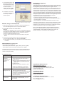
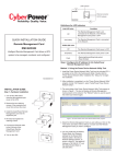
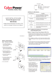
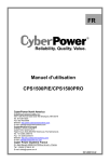
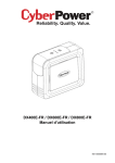
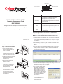
LINK Indicator
Universal connector
Ethernet connector
RX/TX Indicator
Universal
Link
RX/TX
RMCARD203
Definitions for LED Indicators
Link LED color
Off
Condition
The Remote Management Card is not
connected to the Network or the Remote
Management Card power is OFF
QUICK INSTALLATION GUIDE
Remote Management Card
On(Yellow)
RMCARD203
TX/RX LED color
Intelligent Remote Management Card allows a UPS
Off
The Remote Management Card power is OFF
system and environment sensor to be managed,
On(Green)
The Remote Management Card power is ON
monitored, and configured
Flash
The Remote Management Card is connected
to the Network
- Receiving/transmitting data packet
- Reset finished
Step 2. Configure the IP address for the CyberPower
Remote Management Card.
Method 1: Using the Power Device Network Utility Tool
K09-0000081-00
INSTALLATION GUIDE
Step 1. Hardware Installation
1. Turn off the UPS before
removing the expansion port
cover on the UPS.
1. Install the Power Device Network Utility Tool from the included CD. It
is located on the CD in the \tools\nework folder. Double click the
“Power Device Network Utility” installation file, “Setup.msi” to begin
the installation.
2. After installation completes, run the “Power Device Network Utility”
(Under “All Programs”, select “CyberPower Power Device Network
Utility”.)
3. The main dialog of the Power Device Network Utility Tool program is
shown in Figure. 1. The tool will display all Remote Management
Cards present on the network. The "Refresh" button is used to search
the entire local network again.
2. Remove the two retaining
screws of the expansion port
cover, then remove the cover.
3. Install the CyberPower Remote
Management Card into the
expansion port.
4. Re-install and tighten the
retaining screws.
5. Connect the Ethernet cable
to the Ethernet connector of
the CyberPower Remote
Management Card.
6. To connect with the
environment sensor, use the
RJ45 Ethernet cable. Plug
one end into the Universal
connector and the other end
into the sensor.
7. Turn on the UPS.
Figure 1. The main window of the “Power Device Network Utility” program.
4. Select the Remote Management Card you are setting up. Click on the
Tools menu and select “Device Setup” or double click the Remote
Management Card you want to configure.
5. You can modify the IP Address,
Subnet Mask, and Gateway
address for the Device MAC
Address listed in the Device
Network Settings window, as
shown in figure 2. The default IP
Address is 192.168.20.177 and
the default Subnet Mask is
255.255.255.0.
6. Modify the IP, subnet mask
or gateway address. Enter
the new addresses into the
corresponding fields.
Figure 2. The Device Network setting window.
Conformance Approvals
7. You will need to enter a User
Name and Password for the
Remote Management Card
in the authentication window,
as shown in figure 3.
*Default user name: cyber;
Default password: cyber.
FCC Warning
Figure 3. Authentication window.
8. If IP address is successful,
you will see a message that
the IP set up is OK, as
shown in figure 4.
Figure 4. Setup IP Address successfully message.
Method 2: Using a command prompt
1. Obtain the MAC address from the label on the Remote Management
Card. Each Management Card has a unique MAC address.
2. Use the ARP command to set the IP address.
Example:
To assign the IP Address 192.168.10.134 for the Remote Management
Card, which has a MAC address of 00-0C-15-0A-0A-0A you will type in
the following command prompt from a PC connected to the same
network as the Remote Management Card.
(1) Type in “arp-s 192.168.10.134 00-0C-15-0A-0A-0A” then press
Enter.
This equipment has been tested and found to comply with the limits for a
Class B digital device, pursuant to part 15 of the FCC Rules. These limits
are designed to provide reasonable protection against harmful
interference in a residential installation. This equipment generates, uses
and can radiate radio frequency energy and, if not installed and used in
accordance with the instructions, may cause harmful interference to radio
communications. However, there is no guarantee that interference will not
occur in a particular installation. If this equipment does not cause harmful
interference to radio or television reception, which can be determined by
turning the equipment off and on, the user is encouraged to try to correct
the interference by one or more of the following measures:
- Reorient or relocate the receiving antenna.
- Increase the separation between the equipment and receiver.
- Connect the equipment into an outlet on a circuit different from that to
which the receiver is connected.
- Consult the dealer or an experienced radio/TV technician for help.
This device compiles with Part 15 of the FCC Rules. Operation is subject
to the following two conditions: (1) this device may not cause harmful
interference, and (2) this device must accept any interference received,
including interference that may cause undesired operation.
NOTE: THE MANUFACTURER IS NOT RESPONSIBLE FOR ANY
RADIO OR TV INTERFERENCE CAUSED BY UNAUTHORIZED TO
THIS EQUIPMENT. SUCH MODIFICATIONS COULD VOID THE
USER’S AUTHORITY TO OPERATE THE EQUIPMENT.
3. Use the Ping command to assign a size of 123 bytes to the IP.
(1) Type in “ping 192.168.10.134 -l 123” then press Enter.
(2) If the replies are received, your computer can communicate with the
IP address.
WEB INTERFACE Login Account
There are two user account types.
- Administrator (default username : cyber ; default password : cyber)
- Viewer (default username : device ; default password : cyber)
The administrator can access full functions, including enable/disable the
Viewer account, and the view can access the read function but can not
control or change any setting.
Trouble Shooting
Problem
Solution
Unable to configure
the Remote
Management Card
by method 1 or
method 2
1. Check the LED status , the normal condition
is when yellow and green led are both on.
If green led is off :
►Check if the Remote Management Card is
properly seated in the UPS and the UPS
power is on.
If yellow led is off :
►Check if the network connection is valid.
2. Check if the operated PC is on the same
physical network as Management Card is .
Unable to ping the
Management Card
Lost the user name
and password
1. Use method 1 and method 2 to get correct IP
address of the Management Card.
2. If the operated PC is on the different physical
network from the Management Card, verify
the setting of subnet mask and the IP
address of gateway.
Please refer to the “Reset to Default Setting /
Recover from a Lost Password” part in the
user’s manual.
CyberPower North America
CyberPower Systems (USA), Inc.
Phone: (952)-403-9500 Toll-free: (877)297-6937
4241 12th Avenue E. Suite 400, Shakopee, MN 55379
E-mail: [email protected]
Website: www.CPSww.com
CyebrPower Europe
CyberPower Systems, Inc.
E-mail: [email protected]
Website: www.cpsww.eu
CyberPower Systems France
Z.I. Saint Séverin 28220 CLOYES sur le Loir – France
Tél : +33(0)2 37 98 61 50
E-mail : [email protected]