1
SUPERSTORAGESYSTEM 6047R-E1R36N User's Manual
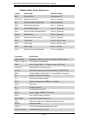
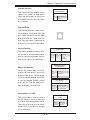
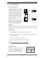
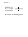
Serial Port Pin Definitions
(COM1/COM2)
Serial Ports
Two serial ports are included on the
serverboard. COM1 is a backpanel
Pin #
Definition
Pin #
1
DCD
6
DSR
port and COM2 is a header located
2
RXD
7
RTS
near the PCI-E slot 1. See the table
3
TXD
8
CTS
on the right for pin definitions.
4
DTR
9
RI
5
Ground
10
NC
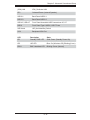
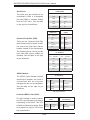
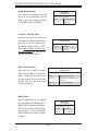
Type A USB Ports
(USB9)
Back Panel USB
(USB 0/1/2/3)
Pin#
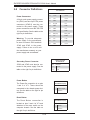
Universal Serial Bus (USB)
There are four Universal Serial Bus
ports located on the I/O panel. In addition, there is one Type A port and two
headers located on the serverboard.
The headers can be used to provide
front side USB access (cables not
included). See the table on the right
for pin definitions.
Definition
Definitions
Pin#
Definition
1
+5V
1
Vcc
2
PO-
2
Data-
3
PO+
3
Data+
4
Ground
4
Ground
5
N/A
5
NA
USB Header
Pin Definitions
Pin #
USB4/6
Definition
Pin #
USB5/7
Definition
1
+5V
1
+5V
2
PO-
2
PO-
3
PO+
3
PO+
4
Ground
4
Ground
5
N/A
5
Key
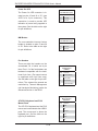
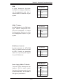
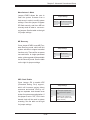
SGPIO Headers
SGPIO Header
Pin Definitions
The SGPIO (Serial General Purpose
Input/Output) headers are used to
communicate with the enclosure
management chip on the backplane.
See the table on the right for pin
definitions.
Pin#
Definition
Pin
Definition
1
NC
2
NC
3
Ground
4
DATA Out
5
Load
6
Ground
7
Clock
8
NC
NC = No Connection
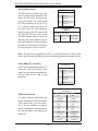
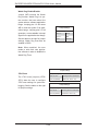
Overheat LED/Fan Fail (JOH1)
The JOH1 header is used to connect
an LED to provide warning of chassis
overheating or fan failure. This LED
will blink to indicate a fan failure. Refer
to the tables on right for LED status
and pin definitions.
OH/Fan Fail LED
States
Overheat LED
Pin Definitions
State
Message
Pin#
Definition
Solid
Overheat
1
5vDC
Blinking
Fan Fail
2
OH Active
5-20