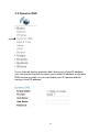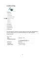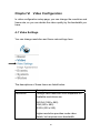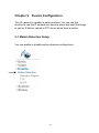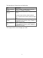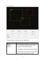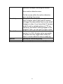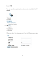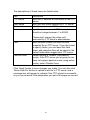
1
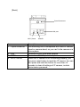
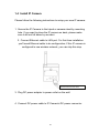
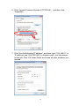
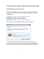
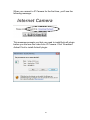
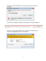
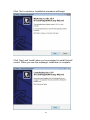
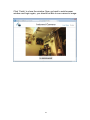
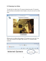
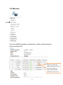
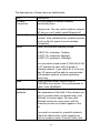
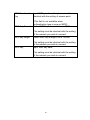
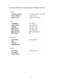
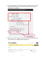
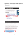
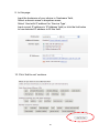
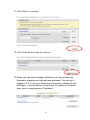
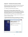
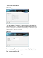
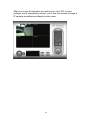
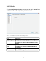
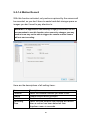
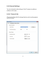
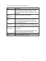
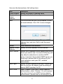
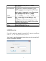
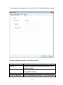
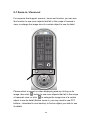
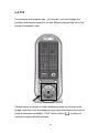
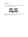
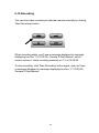
WIRELESS 11N HD IP CAMERA User Manual DN-16026 -CONTENTS- Chapter I Introduction ............................................................................................. 5 1.1 Highlights of your new Network IP Camera ......................................... 5 1.2 Safety Instructions ............................................................................... 6 1.3 Packaging Contents ............................................................................ 7 1.4 Install IP Camera ............................................................................... 10 Chapter II Using Network IP Camera by Web Interface ....................................... 12 2.1 Network Setup ................................................................................................. 12 2.2 Connect to IP Camera’s Web User Interface and Install ActiveX Plugin(for IE browser only) ......................................................................................................... 15 2.3 Viewing Live Video .......................................................................................... 20 Chapter III Setup IP Camera ..................................................................................... 23 3-1 Basic / Network Settings ................................................................................. 24 3-2 Wireless........................................................................................................... 27 3-3 Dynamic DNS .................................................................................................. 32 3-4 Date & Time .................................................................................................... 34 3-5 Users ............................................................................................................... 36 3-6 UPnP ............................................................................................................... 38 3-7 Bonjour ............................................................................................................ 39 Chapter VI Video Configuration .............................................................................. 40 4-1 Video Settings ................................................................................................. 40 4-2 Image Appearance .......................................................................................... 42 Chapter V Events Configuration ............................................................................. 43 5-1 Motion Detection Setup ................................................................................... 43 5-1-1 Detection Region ...................................................................................... 45 2 5-1-2 FTP ........................................................................................................... 48 5-1-3 SMTP........................................................................................................ 50 Chapter VI System Configuration ........................................................................... 53 6-1 ‘Basic’ Settings ................................................................................................ 53 6-1 ‘Advanced’ Settings ......................................................................................... 55 Chapter VII System Status ..................................................................................... 57 7-1 System Information ......................................................................................... 57 7-2 System Log ..................................................................................................... 59 Chapter VIII Advanced Operations ........................................................................... 61 8.1 Apply for free DYNDNS account ..................................................................... 61 Chapter IX Windows Surveillance Utility ................................................................ 68 9-1 Installing IP Camera Administration Software ................................................. 68 9-2 Using IP camera surveillance software ........................................................... 77 9-3 Configure IP camera surveillance software ..................................................... 80 9-3-1 Configure cameras ................................................................................... 80 9-3-1-1 ‘Camera’ tab .......................................................................... 81 9-3-1-2 Schedule Recording.............................................................. 84 9-3-1-3 Audio ..................................................................................... 87 9-3-1-4 Motion Record ....................................................................... 88 9-3-2 General Settings ....................................................................................... 90 9-3-2-1 ‘General’ tab .......................................................................... 90 9-3-2-2 ‘E-Mail Setting’ tab ................................................................ 92 9-3-2-3 Security ................................................................................. 94 9-3-2-4 About ..................................................................................... 96 9-4 Change Display Layout ................................................................................... 97 9-5 Full-screen mode........................................................................................... 100 9-6 Scan .............................................................................................................. 101 9-7 Zoom-in / Zoom-out ....................................................................................... 102 9-8 PTZ................................................................................................................ 103 3 9-9 Snapshot ....................................................................................................... 104 9-10 Recording .................................................................................................... 105 9-11 Video Playback............................................................................................ 106 Chapter X Appendix ............................................................................................. 107 10.1 Troubleshooting ........................................................................................... 107 10.2 Specification ................................................................................................ 108 4 Chapter I Introduction 1.1 Highlights of your new Network IP Camera Congratulations on purchasing this tiny network IP Camera! Its tiny size maximizes portability and eases installation; you can easily install the camera in most places where you need video surveillance. If there’s no Ethernet cable available at the place you wish to install this IP camera, you can use built-in wireless network to connect to your network, and saves the cost of cabling. Other highlights of this network IP Camera include: Compact size and lightweight design, installs anywhere. Mounting hole located at camera’s back, compatible with most of camera tripods. Wireless network with data security (encryption), secures data transfer over the air. Fixed-focus lens, works with most of environments. 5 1.2 Safety Instructions Please obey the safety instructions listed below when you’re using this Network IP Camera, or you would harm this camera and / or yourself! Also, the warranty will become void if you disobey these safety instructions. This Network IP Camera is sophisticated electronic device; do not drop it from high places. Do not place this IP Camera at hot / humid places, and avoid direct sunlight. This IP Camera is not a toy; keep it out from the reach of children. Do not insert any accessories of this IP Camera into your body. If you want to use this IP Camera at any place that may be spilled by water or dirt, a secure and water-proof camera housing is required. Do not pull any cord that is connected to this IP Camera by force. IP Camera will become hot after long time of use. Refrain from touch IP Camera with hand, or cover this IP camera with paper or cloth. If the IP Camera falls into water when powered, do not attempt to retrieve it back by yourself! Find a qualified electric technician for help. 6 1.3 Packaging Contents Please check the contents of your new Network IP Camera when you unpack the package. If any item is missing, please contact your dealer of purchase for help. Item No. 1 2 3 4 5 Description Network IP Camera AC power adapter Ethernet cable User manual Windows Utility CDROM Quick installation guide 7 Quantity 1 1 1 1 1 Familiar with your new Network IP Camera [Front] Antenna Lens Power / WPS LED LAN/WiFi LED Item 1 - Lens 2 - POWER LED 3 - Network LED 4 - Antenna Description IP Camera’s lens. Please keep the lens clean and do not touch by finger. POWER LED will light when the IP camera is powered on, and will flash when resetting IP camera’s settings. (LED light can be switched off even IP camera is powered on when necessary for security reasons) Ethernet LED will light when IP camera is connected to Ethernet network, and it will flash fast when transferring data (It will flash slow when using WPS). (LED light can be switched off even IP camera is powered on when necessary for security reasons) Wireless antenna. Please keep the antenna perpendicular to the ground for best signal reception. 8 [Back] Tripod Connector LAN port WPS / Reset Item 1 - Tripod connector 2 - LAN 3 - 5VDC 4 - WPS / RESET POWER Description This mounting hole is compatible with most of camera tripod or camera stand, so you can fix the camera at a secure place. Connects to your local area network. Connects to 5V DC power adapter. When the IP camera is not functioning properly, you can press reset button to reset the IP camera. You can also press and hold this button for more than 10 seconds to clear all settings of IP camera, include administrator password. 9 1.4 Install IP Camera Please follow the following instructions to setup your new IP camera. 1. Secure the IP Camera to the tripod or camera stand by mounting hole. If you want to place the IP camera on desk, please make sure it will not fall down by accident. 2. Connect Ethernet cable to LAN port. For first-time installation you’ll need Ethernet cable to do configuration; If this IP camera is configured to use wireless network, you can skip this step. Connect Ethernet net cable 3. Plug DC power adapter to power outlet on the wall. 4. Connect DC power cable to IP Camera’s DC power connector. 10 If everything’s ok, you should see the POWER LED light up (and Ethernet LED, if Ethernet cable is inserted). If not, please recheck every step and try again, or ask your dealer of purchase for help. Please note if you configured IP camera to switch LED lights off, two LED lights won’t light. 11 Chapter II Using Network IP Camera by Web Interface 2.1 Network Setup This IP camera’s default IP address is 192.168.2.3, and you must use a computer that uses 192.168.2.x IP address to connect to it. Please follow the following instructions to setup your computer’s IP address: 1. Please click ‘Start’ button and then click ‘Control Panel’. 12 2. Click ‘View network status and tasks’ under ‘Network and Internet’ 3. If you didn’t see ‘Network and Internet’ in control panel, please look for ‘Network and Sharing Center’ icon and double-click it. 4. Click ‘Local Area Connection’ 5. Click ‘Properties’ 13 6. Click ‘Internet Protocol Version 4 (TCP/IPv4), and then click ‘Properties’ 7. Click ‘Use the following IP address’, and then input ‘192.168.2.1’ in ‘IP address’ and ‘255.255.255.0’ in Subnet mask’, just like shown on the left. Click ‘OK’ when finish, and close all open windows you opened 14 2.2 Connect to IP Camera’s Web User Interface and Install ActiveX Plugin (for IE browser only) For first-time installation, you can connect to IP camera by Internet Explorer web browser by entering its default IP address: 192.168.2.3 in address bar: The use login screen will appear when you get connected: IP Camera’s administrator username is ‘admin’ (lower case) and password is ‘1234’ by default. Click ‘OK’ button or press ‘ENTER’ key on your keyboard when you finish entering username and password. 15 When you connect to IP Camera for the first time, you’ll see the following message: This message prompts you that you need to install ActiveX plugin before you can see the video from IP Camera. Click ‘Download ActiveX’ link to install ActiveX plugin: 16 Click ‘Run’ to start installation. After few seconds, you’ll see this message: For IE9: The message will appear at the bottom of Internet Explorer: Click ‘Run’ to begin installation. You may see UAC (User Account Control) message after you click ‘Run’ button: 17 Click ‘Yes’ to continue. Installation procedure will begin: Click ‘Next’ and ‘Install’ when you’re prompted to install ActiveX control. When you see this message, installation is complete: 18 Click ‘Finish’ to close the window. Now, go back to web browser window and login again, you should be able to see camera’s image: 19 2.3 Viewing Live Video To view the live video from IP camera, please log onto IP camera’s web interface as described in last chapter, and you can see live video view: When you’re in other setup pages of IP camera, you can click ‘Live View’ link located at the upper-right corner of IP camera’s web interface: 20 There are also some functions you can use in camera’s live view page: The descriptions of these items are listed below: Item Snapshot Record Fit to window Full Screen Digital Zoom Description Take a snapshot (save a picture) of current live view. Click the folder field (‘c:\’ by default) and you’ll be prompted to select a folder in your computer, and click ‘Get snapshot’ button to save a picture. Start recording video. Click the folder field (‘c:\’ by default) and you’ll be prompted to select a folder in your computer, and click ‘Start recording’ button to start recording. Click this button and the live view area will adjust according to the size of web browser automatically. Click this button and the live view will expand and fit the size of your computer monitor. Press ‘Esc’ key on your keyboard to resume. Click this button and a new window will popup: Check ‘Enable’ box to enable digital zoom 21 (enlarge video so you can see objects in detail). Drag the slide bar from 100% (no enlargement) to 400% to enlarge the image. The level of enlargement will be displayed in ‘Zoom Factor’ field. When you’re enlarging image (i.e. Zoom Factor > 100%), a green rectangular will appear in the image area: Drag the green rectangular to move the position of enlarged area in image. 22 Chapter III Setup IP Camera To setup the IP camera, please log onto IP camera’s web interface and click ‘Setup’ link on the upper-right corner: The setup menu will appear: There are five setup categories: Basic, Video, Events, System, and Status, which are located at the left of web interface. When you click on the link of every category, it will expand and show sub-menu. Please refer to following chapters for detailed instructions. 23 3-1 Basic / Network Settings In this menu, you can setup Ethernet network settings. (NOT Wireless Network!) 24 The descriptions of these items are listed below: Item Network Type Description Select the type of Ethernet connection: Static IP, DHCP, and PPPoE. Please select one from dropdown menu, if you’re not sure, please consult your network administrator or ISP. Static IP: IP: Please assign an IP address to this IP camera. Netmask: Please input the netmask of IP address. Gateway: Please input the gateway address of your network. Primary DNS: Input the IP address of DNS server. Secondary DNS: Input the IP address of secondary (backup) DNS. You can leave this field blank if no secondary DNS is available. HTTP port: The default web port number is 80, if you want to change it, you can input it from 25 1024 ~ 65535 in this field. When you connect to this IP camera next time, you have to add a colon and port number after IP camera’s IP address. For example, if the camera’s IP address is 192.168.2.3 and HTTP port number is 82, you have to input ‘http://192.168.2.3:82’ in web browser’s address bar. DHCP: IP camera will obtain IP address from DHCP server on your local area network automatically. PPPoE: IP camera will connect to network by PPPoE. Please input PPPoE user name and password, and input MTU value when required. Please note: In some cases you can improve network efficiency or correct connection problem by setting a new MTU value, however, In most cases you don’t have to change MTU setting. Click ‘Apply’ button to save changes you made. 26 3-2 Wireless You can establish wireless connections to other network devices such as network AP. When you enter this page, IP camera will scan for wireless devices nearby automatically and display them here. 27 The descriptions of these items are listed below: Item Wireless Connection Network Type Mode Description You can enable or disable wireless functionality here. Please note: You can switch wireless network off, but you can’t switch wired Ethernet off. Select the type of network you wish to connect: Infra (infrastructure: wireless access point) or Ad Hoc (point to point wireless connection). Select the wireless operating mode: B (802.11b, maximum 11mbps) G (802.11g, maximum 54mbps) N (802.11n, maximum 150mbps). Band Available Networks You can select mixed mode (2.4GHz B+G+N) so IP camera will work with all kinds of wireless network. If you select B, G, or N only, then IP camera will be able to communicate with wireless network of same operating mode only. Select wireless band: 20MHz only or 20/40MHz auto switch. It’s recommended to select ‘Auto 20/40MHz’. IP camera will list all nearby networks and their parameter in this field. If the network you wish to connect does not appear hear, click ‘Refresh’ to rescan again. You can click ‘Refresh’ button for many times until the network you wish to connect appear in the list. If you wish to connect to a specific network, select the radio button of the network you wish to connect (under ‘Connect’ field), and 28 the network’s connection parameter will appear in the fields below. SSID Channel Authentication Tips: If you can’t see the network you wish to connect after you click ‘Refresh’ button for many times, please move IP camera closer to the network’s access point). Input network’s SSID (access point’s wireless name) here, or select one network from network list above. If he network you wish to connect is a ‘hidden’ network (SSID is hidden to the public), you have to input SSID manually. Select wireless channel number. Use ‘Auto’ to select channel automatically. Select authentication type: None: no encryption WEP: use WEP encryption WPA-PSK: Use WPA with PSK encryption. WPA2-PSK: Use WPA2 with PSK encryption. Encryption Type The authentication type you selected here must be identical with the setting of access point. Select wireless encryption type. This option will vary depends on the authentication type of the network you wish to connect. The encryption type you selected here must be identical with the setting of access point. 29 WPA Pre-shared Key Input WPA pre-shared key here, must be identical with the setting of access point. WEP Key Format (This field is not available when authentication type is none or WEP). Select WEP key’s format: Hex or ASCII. WEP Key length This setting must be identical with the setting of the network you wish to connect. Select WEP key’s length: 64 or 128-bit. WEP Key This setting must be identical with the setting of the network you wish to connect. Input WEP key here. This setting must be identical with the setting of the network you wish to connect. 30 You can also setup encrypted wireless connection by WPS (Wi-Fi Protected Setup): The descriptions of these items are listed below: Item Self PinCode Configure via Push Button Configure via PinCode Description Displays the 8-digit pin code of this IP camera. Write this number down and you’ll need this number so get connected with other WPS-enabled network devices when requested. Click ‘Start PBC’ button to start PBC-style WPS pairing sequence: Click this button, and push WPS button of the access point (or click a software button in access point’s configuration web page). You must press WPS button of the wireless device you wish to connect within 120 seconds. Click ‘Start PIN’ to start PIN-style WPS pairing sequence. You have to input WPS registrar’s SSID in ‘Registrar SSID’ field first. Click ‘Apply’ button to save changes you made. 31 3-3 Dynamic DNS If your Internet service provider didn’t issue you a fixed IP address, you can use this function to report your current IP address to dynamic DNS service provider, so you can locate your IP camera without having a fixed IP address. 32 The descriptions of these items are listed below: Item Enable DDNS Provider Host Name User Name Password Description Select ‘Enable’ to enable DDNS functionality, orselect ‘Disable’ to disable DDNS functionality. Select Dynamic DNS service provider you’re using from dropdown menu. Input the hostname you registered with DDNS service provider. Input the user name you registered with DDNS service provider. Input the password you registered with DDNS service provider. Click ‘Apply’ button to save changes you made. TIPS: You can register free (or paid) dynamic DNS service from following website: Dyndns: www.dyndns.org Refer to Chapter VIII for DDNS application. 33 3-4 Date & Time You can setup IP camera’s system date and time here. Maintaining a correct system time is very essential when you need to replay recorded video. 34 The descriptions of these items are listed below: Item Mode Description Select date & time setup mode: Manually: Set time manually. Set Date/Time Manually Synchronize to PC time NTP Server Time Zone Daylight Saving NTP: Use NTP (Network Time Protocol) to setup date and time automatically via network. If you have Internet connection or there’s a NTP server on your local network, you can select this function to help you to keep IP camera’s date and time correct. There are 6 fields for you to input current date / time. The format is: YYYY/MM/DD HH:MM:SS Click this button the fill date / time field with your computer’s date and time. Input NTP server’s hostname or IP address. Select the time zone of the place you live from dropdown menu. If the area you live uses daylight saving, select ‘Enable’, or select ‘Disable’ when daylight saving is not used. Click ‘Apply’ button to save changes you made. 35 3-5 Users Besides default system operator account ‘administrator’, you can add additional operator account or user account here: Operator accounts can perform all functionalities and do configurations of this IP camera, while guest accounts can view image only. 36 The descriptions of these items are listed below: Item User List Description Lists all existing operators / users here. To modify an operator / user’s setting, click his / her name here first. User Name Input user’s name here. Password Input user’s password here. Confirm password Input user’s password here again for confirmation. Authority Select this user’s privilege: Operator can view video and go to setup page to change video setting. Guest can view video only. Add Click this button to add a new user with settings above. Modify Click this button to save changes of an existing user. Remove Click this button to remove a user. You must select a user in ‘User List’ field first. Anonymous Login Select ‘Enable’ to enable anonymous user to login this IP camera and view image. This function is useful when you want to establish a remote video server which welcomes everyone to view the video. If you only want to allow registered user to login, select ‘Disable’. Click ‘Apply’ button to save changes you made. 37 3-6 UPnP When you enable this function, Windows computers can discover this IP camera from windows network neighbor directly, and you don’t have to know this IP camera’s IP address in advance (This only works on local area network). Select ‘Enable’ to enable this function, or select ‘Disable’ to prevent users on local area network to discover this IP camera. 38 3-7 Bonjour When you enable this function, Macintosh computers can discover this IP camera from safari web browser directly, and you don’t have to know this IP camera’s IP address in advance (This only works on local area network). Select ‘Enable’ to enable this function, or select ‘Disable’ to prevent users on local area network to discover this IP camera by safari browser. Tips: Bonjour function must be enabled in safari browser first. 39 Chapter VI Video Configuration In video configuration setup page, you can change the resolution and frame rate, so you can decide the video quality by the bandwidth you have. 4-1 Video Settings You can change resolution and frame rate settings here. The descriptions of these items are listed below: Item Resolution Description Change video resolution from dropdown list. Available resolutions are: SXVGA (1280 x 960) VGA (640 x 480) QVGA (320 x 240) Higher resolution provides mode video details, but requires more bandwidth. 40 MAX. Frame rate Power frequency Select the maximum video frame rate. Higher frame rate provides more fluent video, but also requires more bandwidth. Please note: When the environment is dark, this IP camera will automatically adjust frame rate to a lower setting to provide better video quality by using a longer exposure time. Select the AC utility power’s frequency (50 or 60Hz). This will help reduce the flicker of video when there’s certain kind of lamp. If you don’t know the frequency of power you’re using, you can consult your utility power company. Click ‘Apply’ button to save changes you made. 41 4-2 Image Appearance You can change video appearance settings here. The descriptions of these items are listed below: Item Brightness / Contrast / Saturation / Sharpness / Hue Reset to default Save value Description Change video’s appearance. If you think you don’t like the video as it appears, you can change these parameters. Drag the blue lever by mouse to change the value. Click this button to reset all settings back to default value (50). Save changes you made. 42 Chapter V Events Configuration This IP camera is capable to detect motions. You can use this function to use this IP camera as a security alarm and send the image to you by E-Mail or upload to FTP server when there’s motion. 5-1 Motion Detection Setup You can enable or disable motion detection settings here. 43 The descriptions of these items are listed below: Item Motion Detection enable Motion Detection Interval Send snapshot to E-Mail Send snapshot to FTP Description Select ‘Enable’ to enable motion detection function, or ‘Disable’ to disable it. Select the time interval this IP camera detects motion. To detect minor motions, select a shorter time; to ignore minor motions, select a longer time. Select ‘Enable’ to send a snapshot picture to designated email recipient; select ‘Disable’ to disable this function. Select ‘Enable’ to upload a snapshot picture to designated FTP server; select ‘Disable’ to disable this function. Click ‘Apply’ button to save changes you made. 44 5-1-1 Detection Region You can setup the area in video where IP camera should detect changes in video (motion). Motions outside of detection region will be ignored by IP camera, and IP camera will do nothing when a motion is detected outside of detection region. This will help you to minimize the chance of false alarm. When you select this setup page, you’ll see the following setup page: (The setup page’s video view window is intentionally set to black so you can see 3 motion detection regions clearly). 45 The descriptions of these items are listed below: Item Region 1 / Region 2 / Region 3 Description Check the box to enable this motion detection area. A rectangle will appear on the video view when it’s checked (enabled). To change the size of motion detection area: Point the mouse to the upper-left, upper-right, lower-left, lower-right corner of motion 46 detection rectangle, and drag the mouse. Move motion detection area: Sensitivity Threshold Refresh Save Put the mouse within the motion detection area, and drag the mouse. Change the sensitivity of motion detection. Set to a higher value (right) and IP camera will trigger the alarm when there’re only small changes in video. If you found that IP camera sends E-mail or uploads picture to FTP too frequently, and there’s nothing happen in the snapshot video, you can set to a lower value. Set the motion detection threshold here (input number 0 to 100). A higher value represents IP camera will only trigger alarm when the object in motion detection area is really big. Refresh the reference picture. Save changes you made in this page. 47 5-1-2 FTP You can upload a snapshot picture when motion detected by this IP camera. When you select this setup page, you’ll see the following setup page: 48 The descriptions of these items are listed below: Item FTP Server User Name Password Port Path Passive mode Description Input the IP address or host name of the FTP server. Input the user name required by FTP server. Input the password of FTP server. Input the port number of FTP server, this should an integer between 1 to 65535. Please don’t change this value until instructed by FTP server’s administrator. Input the path (folder) you wish to save snapshot file on FTP server. If you don’t want to specify folder, you can leave this field blank, and snapshot files will be saved in the default folder when logged onto FTP server. Default setting is ‘Enable’ (use passive mode). If the FTP server you’re going to use does not support passive mode (using active mode), select ‘Disable’ here. Click ‘Apply’ button to save changes you made. You can also click ‘Send a test file’ button to upload a test file to FTP server, and a message box will appear to indicate if the FTP upload is successful, so you can examine if the parameters you set in this page are correct. 49 5-1-3 SMTP You can send a snapshot picture by E-Mail when motion detected by this IP camera. 50 When you select this setup page, you’ll see the following setup page: The descriptions of these items are listed below: Item Public Server SMTP Server SMTP Port Recipient E-Mail Address Description If you’re using Hotmail, Yahoo mail, or Google mail, select appropriate item from dropdown menu, and IP camera will fill the SMTP server address and port number for you automatically. Input the host name or IP address of SMTP server. SMTP server is usually provided by your ISP. Input the SMTP port number here. Most of SMTP servers use port number ‘25’, while some SMTP servers uses encrypted connection and port number is ‘465’. Consult mail server administrator when in doubt. Input E-mail recipient (receiver)’s E-mail address here. 51 Sender E-Mail Address SSL/TLS SMTP Authentication Account Password Input an E-Mail address here, which will be used by E-Mail sender’s address. This will help you to identify the E-Mail sent by this IP camera, and will help you to prevent problems caused by anti-spam software. Select ‘SSL or TLS’ when your SMTP server requires encryption. When in doubt, consult your SMTP server administrator. Select ‘Enable’ when your SMTP server requires authentication. When in doubt, consult your SMTP server administrator. Input SMTP account when your SMTP server requires authentication. Input the password used for SMTP server authentication. Click ‘Apply’ button to save changes you made. You can also click ‘Send a test E-mail’ button to send a test E-mail to SMTP server, and a message box will appear to indicate if the E-mail send is successful, so you can examine if the parameters you set in this page are correct. 52 Chapter VI System Configuration You can configure the basic system settings in this setup page, or backup / restore system configurations. 6-1 ‘Basic’ Settings You can set the camera’s name and password here. You can also change the behavior of LED lights. 53 The descriptions of these items are listed below: Item IPCamera Name Description Set the name of IP camera. It’s recommended to use a meaningful name which can describe the location where the IP camera is installed. This will help you to identify IP camera when you have more than one IP cameras. Administrator Input administrator’s new password here if Password you want to change it. Confirm Password Input administrator’s new password here again for confirmation. LED Indication For security reasons, you can disable the LED lights in front of IP camera by select ‘off’ here, so other people can’t identify if the IP camera is working by them. Click ‘Apply’ button to save changes you made. 54 6-1 ‘Advanced’ Settings You can save or restore IP camera’s configuration file here. You can also reboot the IP camera remotely here. The descriptions of these items are listed below: Item Firmware Filename Backup Config Description You can improve the functionality of this IP camera by uploading new firmware file when available. Please download new firmware file from our website, and save it to your computer’s hard disk. Then, click ‘Browse’ button to select the file on your hard disk, and click ‘Apply’ button to upload the firmware to IP camera. Click ‘Apply’ button to download current configuration as a file and save it on your computer’s hard drive. 55 Restore Config Reboot Now Reset to default Click ‘Browse’ button to select a previously-saved configuration file on your computer’s hard drive, and then click ‘Apply’ to upload the configuration file. Click this button to reboot IP camera. This function is useful when you think IP camera is not working properly. Reset the IP camera’s setting back to default value. There are 2 options: 1) Keep Network Setting: Reset all settings back to default value, except network settings. You can still use the same IP address to connect to the IP camera. 2) Factory Default: Reset all settings, include network settings. Please reconnect to IP camera by its default IP address: 192.168.2.3 Click ‘Apply’ to reset. You can press and hold ‘WPS / Reset’ button for more than 10 seconds to reset IP camera’s setting to default value. 56 Chapter VII System Status You can view the status of this IP camera, which is helpful when you need to do detailed configuration, or debug. 7-1 System Information You can see system-wide information of this IP camera here. 57 A system information summary page will appear like this: 58 7-2 System Log The IP camera’s usage and actions will be displayed here. The system log will appear here, you can use scroll bar to view logs, with some adjustable parameters: 59 The descriptions of these items are listed below: Item Log Level Remote Log Remote Log Server Description Select the log level from dropdown list. Select 0 and the IP camera will only log very important information, or select 4 to log everything. This IP camera can send log information to a remote server for archive. Select ‘Enable’ to enable this function. This IP camera supports syslog log server. Input the IP address or host name of log server you wish to use. Click ‘Apply’ button to save changes you made. 60 Chapter VIII Advanced Operations In this chapter, you’ll learn how to apply a free DYNDNS account to use with this IP camera when you don’t have a fixed IP address, and view the video of this IP camera on your iPhone. 8.1 Apply for free DYNDNS account If your ISP issues you with an IP address which is not fixed, please follow the following instructions to apply for a free DYNDNS account to get a host name which is dynamically mapped to your current IP address. 1. Launch your web browser and navigate to http://www.dyndns.org 61 2. Click ‘Sign In’ button (located at upper-right corner of dyndns.org’s webpage) 3. Click ‘Create an Account’ in pop-up menu. 62 4. Fill all fields appear in this menu, and click ‘Create Account’ button to create a new account. You’ll be prompted if the account you selected is not available. 5. When you see this image, you’ll receive an e-mail confirmation at the e-mail box you registered with dyndns.org. 63 6. Check your e-mail box and you should be able to get confirmation e-mail. Click the link to connect to dyndns.org website and complete registration procedure. If you didn’t get the mail, please re-check the e-mail address, or click ‘resending it’ link in last step. Also, if nothing happen after you click the link, please copy the link text and paste it in web browser’s address bar. 64 7. When you see ‘Account Confirmed’ webpage, indicates your dyndns.org account has been confirmed and activated. Now you can click ‘Create a dynamic DNS host within our Free domains’ link to continue. 8. Click ‘Create Hostname’ button. 65 9. In this page: Input the hostname of your choice in ‘Hostname’ field, Select a domain name in dropdown menu, Select ‘Host with IP address’ for ‘Service Type’, Input current IP address in ‘IP Address’ field (or click the link below to use detected IP address to fill this field’. 10. Click ‘Add to cart’ continue. 66 11. Click ‘Next’ to continue. 12. Click ‘Activate Services’ to continue. 13. When you see this message, indicates your free dyndns.org hostname mapping service has been activated. You can go to chapter 2-2-3 to use your dyndns.org username, password, and hostname + domain name to locate your IP camera on Internet even you’re using dynamic IP address! 67 Chapter IX Windows Surveillance Utility Besides using web browser to operate this IP camera, you can also use windows utility to use this IP camera, which provides faster access to all functions of this IP camera. 9-1 Installing IP Camera Administration Software There are two files in the surveillance software’s folder: Setup_Admin_xxx and Setup_Viewer_xxx (xxx is version number and will be different as the version number changes). Please install Administration software first. You can use administration software to locate and administer IP cameras on your local area network. Please note that you still have to configure remote IP cameras (i.e. IP cameras on Internet) manually. 1. Double click the Setup_Admin_xxx file located in ‘xxx’ folder in supplied CD-ROM, when the following window appears, click ‘Next’. 68 2. You can specify the destination folder of software installation, you can just use the default folder, and click ‘Next’ to continue. 3. If you need installation program to create a desktop icon or a quick launch icon for you, click all items you need here, than click ‘Next’ to continue. 69 4. Here lists all options you chose in previous steps, if everything’s correct, click ‘Install’ to start installing procedure, or click ‘Back’ to go back to previous step to modify installing settings. 5. The installing procedure will take some time, please be patient. 70 6. When you see this window, it means the software installing procedure is complete. Please click ‘Finish’ to finish the procedure (IP camera surveillance software will start after you click ‘Finish’ button, if you want to start it later, uncheck ‘Launch IPCam Surveillance Software’ box). 7. After software is launched, you can click cameras on your local area network. 71 button to search for IP 8. When one (or more) IP camera(s) is found: you can click button to connect to IP camera by web browser, or button to configure its setting. You’ll be prompted to input IP click camera’s administrator username and password if you wish to configure it: 72 There are two setting pages. LAN Setting: You can configure IP camera’s IP address setting in this page. You can either use ‘DHCP’ (IP camera will acquire IP address from DHCP server on your local area network automatically), or ‘Manual IP’ (you have to input IP address manually). Security: You can change IP camera’s name, and change its administrator password here by inputting new password in both ‘New Password’ and ‘Confirm Password’ field. 73 9.2 Install Video Viewer 1. Double-click Setup_Viewer_xxx file to start installation. 2. Click ‘Next’ to continue. 74 3. You can uncheck the boxes here if you don’t want to create desktop / quick launch icon, and click ‘Next’ to continue. 4. Please check if everything’s correct here. If you want to change any setting, click ‘Back’ to go back to previous page, or click ‘Install’ to start installation. 75 5. Installation procedure takes few seconds to few minutes to complete, please be patient. 6. Installation is complete when you see this message. You can click ‘Finish’ to finish installation procedure and launch utility, or unckeck ‘Launch IPCam Surveillance Software’ box before you click ‘Finish’ button if you don’t want to launch software after installation is complete. 76 9-2 Using IP camera surveillance software You can click ‘IPCam Surveillance Software’ icon from desktop, quick launch bar, or start menu to start the IP camera surveillance software. Before you start: IP camera surveillance software will only work when your monitor’s resolution is ‘1024 x 768’. Please change the resolution before you use IP camera surveillance software, or it won’t start. Here are descriptions for all components of IP camera surveillance software: Video displaying area Language Display layout Full screen / Scan Zoom Out / Zoom In PTZ Control / Home Close window (stop surveillance) / Minimize window Message display box Recording / System configure Playback / Snap shot 77 You can put the mouse cursor on a certain component and see its button name, and here’re detailed descriptions of all buttons: Item Video displaying area Language Display layout Full screen Scan Zoom out Zoom In PTZ control Home Description The image of all connected cameras will be displayed here. Select a language from this dropdown menu to change display language. Change camera image display layout (Click a layout icon to change camera display layout). There are 8 kinds of available display layouts. Click this button to switch to full screen mode (only display all camera’s image), press ‘ESC’ key to quit full screen mode. Click this button and the IP camera surveillance software will switch displaying the image of all connected camera automatically. Click this button once to activate scan function (scan icon will become blue ), click again to stop scanning (scan icon will become white ). Zoom-out (To see more objects). This function is only available for supported cameras. Zoom-in (Too see more details). This function is only available for supported cameras. There are 8 directions in PTZ control ring. If the camera you connect support PTZ, you can use PTZ control ring to change the direction that camera points to. This function is only available for supported cameras. Click this button to return the camera to ‘Home’ (default) position. This function is only available for supported cameras. 78 Recording Start video recording. Configure Software / camera configuration. Playback Playback a recorded video file. Snapshot Take a snapshot of current camera. Message display Close window (stop surveillance) Displays all system messages like camera is disconnected etc. Terminates IP camera surveillance software. Minimize window Minimizes IP camera surveillance software window. Video displaying area Displays the image of all cameras by the display layout you selected. 79 9-3 Configure IP camera surveillance software 9-3-1 Configure cameras Before you use this IP camera surveillance software, you must configure the camera(s) you wish to connect. Please click ‘System and a popup menu will appear: configure’ button Please select ‘Configure Cameras’ to configure cameras: Note: If you’re prompted by a windows security alert which asks you if you want to block ‘IPCamViewer’ program, please click ‘Unblock’ button, of IP camera surveillance software will not be able to function correctly. 80 9-3-1-1 ‘Camera’ tab In this tab you can configure all cameras you wish to connect. Up to 16 cameras can be connected simultaneously: Here are the descriptions of all setting items: Item Channel Camera Search Select Refresh Description Select the channel number you wish to set. All cameras found on your local network will be displayed in ‘Camera Search’ box. Select a camera listed in ‘Camera Search’ box, and click ‘Select’ button to fill all parameters of selected camera in every camera configuration fields. Rescan all cameras on your local network. If you didn’t see the camera you expected in ‘Camera Search’ box, or new cameras has been joined to your local network after last scan. 81 Name* Input the name of camera here. Default value is the first 6 bytes of camera’s MAC address, you can change the name of camera so you can remember the camera’s location of purpose easily. Model Displays the model of selected camera, this field can not be changed. IP* Input the IP address of camera. Username* Input the user name of camera. Web Port* Input the web port of the camera. By default it’s ‘80’. Password Input the password of camera. Default value is ‘1234’. You should change the password if you changed the password of selected camera. Video Select the video encoding format of this camera Format** (MJPEG or MPEG4). Reset Clear all fields in ‘Camera Configuration’ section. OK Save settings in this tab. Cancel Discard all settings in this tab. *: It’s recommended to use ‘Select’ button to fill the content of this field. **: Only available for cameras support this function. 82 After you’ve set all channels you wish to set, click ‘OK’ to save settings, and if everything’s correct, you’ll see the camera’s image in IP camera surveillance software’s main menu: 83 9-3-1-2 Schedule Recording In this tab, you can setup scheduled video recording, so you can record the video captured by all cameras you have by a pre-defined schedule. Here are the descriptions of all setting items: Item Channel One Time Schedules Description Select the channel number you wish to set. You can specify the one-time schedule for selected camera; this schedule will be executed once only. 84 New (One Time Schedules) Click this button and a new window will appear: Please specify the time duration of this one-time schedule (the date and time of ‘From’ and ‘To’), then click ‘OK’ to save settings. Edit Delete New (Weekly Schedules) Please note you must set a schedule that will be happened in the future, you can not set a schedule in the past. You can modify a scheduled recording item. Select a schedule in ‘One Time Schedules’ list, and click ‘Edit’ button to edit the start and end time of this schedule. Delete a selected schedule item. Click this button and a new window will appear: 85 You can define recording schedule that will be executed at the specified time of certain weekday(s) in a week. Please check all weekdays that applies, and set the start time in ‘From’ field. You can set the duration of video recording in ‘Period’ field (format is HH:MM:SS), and the end time will be calculated automatically and displayed in ‘To’ field. You can also click ‘All Time Record’ button to define a recording schedule that will be executed every weekday, from 12:00:00AM to 11:59:59PM. Edit Delete OK Cancel Click ‘OK’ to save changes. You can modify a scheduled recording item. Select a schedule in ‘One Time Schedules’ list, and click ‘Edit’ button to edit the start and end time of this schedule. Delete a selected schedule item. Save settings in this tab. Discard all settings in this tab. 86 9-3-1-3 Audio For cameras that support audio, you can use this tab to decide if you wish to hear the audio captured by selected camera. Here are the descriptions of all setting items: Item Channel Mute Audio Record Video Only OK Cancel Description Select the channel number you wish to set. Check this box and the IP camera surveillance software will not play the audio captured by this camera. Check this box and the IP camera surveillance software will not record the audio captured by this camera. Save settings in this tab. Discard all settings in this tab. 87 9-3-1-4 Motion Record With this function activated, only motions captured by the camera will be recorded, so you don’t have to waste hard disk storage space on images you don’t need to pay attention to. WARNING: For applications that security is highly concerned, it’s not recommended to use this function since some tiny changes you may need to know may not be able to trigger the camera and the camera will not start recording. Here are the descriptions of all setting items: Item Channel Enable Disable Recording Time Description Select the channel number you wish to set. Enable motion record function. Disable motion record function. Select the time duration that camera will record when a motion has been detected from dropdown menu in seconds. 88 Invoke alarm when motion is triggered Send mail when motion is triggered OK Cancel Send an alarm when a motion has been detected by the camera. Send an email to a pre-defined address when a motion has been detected by the camera. Save settings in this tab. Discard all settings in this tab. 89 9-3-2 General Settings You can set system-wide settings of this IP camera surveillance software in this menu. 9-3-2-1 ‘General’ tab All general settings like file storage directory and recording spaces can be set here. 90 Here are the descriptions of all setting items: Item Data Directory Description Set the directory (folder) you wish to store the recorded video and captured image. You can click ‘Browse’ button to pick a directory in your hard disk. Displays remaining storage space. Free Recording Space Max Video File Defines the maximum file size of every video file. Size When the size of file exceeds this value, IP camera surveillance software will open another file to record the video. Scan Time Define the time period to pause between every camera switch when you activate ‘Scan’ function. Cycle You can decide the behavior when hard disk Recording space is full: OK Cancel Disable: Do not overwrite recorded video files. Enable: Overwrite recorded video files. Save settings in this tab. Discard all settings in this tab. 91 9-3-2-2 ‘E-Mail Setting’ tab If you want to use motion detection function and wish to get an email that contains the image captured by the camera, please setup your email related parameters here first. 92 Here are the descriptions of all setting items: Item E-Mail Subject Recipient E-Mail Address New Edit Delete Sender E-Mail Address SMTP Server SMTP port SMTP Auth Description Specify the subject of sending email. Here lists all email addresses you set. Click this button and you’ll be prompted to input the email address. Click ‘OK’ to save changes. Select an email address from ‘Recipient E-Mail Address’ box, and click ‘Edit’ to edit the email address. Delete selected email address. Specify the email address of email sender. Specify the IP address or host name of the SMTP server you wish to use. For most of ISPs they will only allow its subscriber to use their SMTP server, if you don’t know which SMTP server you should use, please refer to the setting of your email software or ask your ISP / network administrator. Specify the port number of the SMTP server you wish to use here. By default (and the setting of most of SMTP servers) it’s ‘25’. Select ‘Enable’ if your SMTP server requires authentication, select ‘Disable’ if it’s not required. If you don’t know if your SMTP server requires authentication, please refer to the setting of your 93 email software or ask your ISP / network administrator. SMTP Account Input the SMTP account (username) of your SMTP server here. In most cases, it’s the same with your POP3 username (the one you used to receive email). Please refer to the setting of your email software or ask your ISP / network administrator if you’re not sure about this. SMTP Input the SMTP password of your SMTP server Password here. In most cases, it’s the same with your POP3 password (the one you used to receive email). Please refer to the setting of your email software or ask your ISP / network administrator if you’re not sure about this. OK Save settings in this tab. Cancel Discard all settings in this tab. 9-3-2-3 Security If you don’t want other people to access this IP camera surveillance software, you can set a password to protect it. You’ll need to input the password every time you wish to use this IP camera surveillance software: 94 To set password, please use ‘Security’ tab in ‘General Options’ menu: Here are the descriptions of all setting items: Item Enable Disable Password Confirm Password Description Requires password authentication when this software starts. Password authentication is not required when this software starts. Input the password you wish to use here. Input the password you wish to use here again. 95 9-3-2-4 About This tab shows the version number of the IP camera surveillance software you’re using. 96 9-4 Change Display Layout This IP camera surveillance software provides 8 kinds of display layout: Every layout displays different number of camera and camera arrangement, you can click the icon that presents a specific kind of layout, and the video displaying area will change accordingly. Layout style 1: Displays the video of 1 camera only. 1 Camera only Layout style 2: 4 Cameras Displays the video of up to 4 cameras. 97 Layout style 3: 6 Cameras Displays the video of up to 6 cameras. Layout style 4: 8 Cameras Displays the video of up to 8 cameras. Layout style 5: 9 Cameras Displays the video of up to 9 cameras. Displays the video of up to 10 cameras. Layout style 6: 10 Cameras 98 Layout style 7: 13 Cameras Displays the video of up to 13 cameras. Layout style 8: 16 Cameras Displays the video of up to 16 cameras. 99 9-5 Full-screen mode If you want to use all available spaces on your monitor to display surveillance image, you can click ‘Full Screen’ button to switch display mode to full-screen mode. To exit full-screen mode, press ‘ESC’ key. 100 9-6 Scan If you have more than one camera configured, and you wish to switch the displaying image between cameras, you can click ‘Scan’ button to switch between all configured cameras. NOTE: If a camera is configured but disconnected, it will still be displayed in a scan sequence (you’ll see nothing and you’ll see ‘Disconnected’ text displayed at the upper-left corner of display image). Click ‘Scan’ button once to activate scan function (scan icon will become blue ), click again to stop scanning (scan icon will become white ). 101 9-7 Zoom-in / Zoom-out For cameras that support zoom-in / zoom-out function, you can use this function to see more objects that fall in the scope of camera’s view, or enlarge the image size of a certain object to see its detail. Please select a camera in video displaying area by clicking on its image, then click button to see more objects that fall in the scope of camera’s view, or click to enlarge the image size of a certain object to see its detail (Before zoom-in, you may need to use PTZ buttons - described in next section) to find an object you wish to see its detail). 102 9-8 PTZ For cameras that support pan - tilt function, you can change the position that camera points to, to see different places that fall in the scope of camera’s view. Please select a camera in video displaying area by clicking on its image, and then click the directions you wish the camera to move to (total 8 directions available). Click ‘Home’ button ( camera’s home (default) position. 103 ) to return to 9-9 Snapshot You can take a snapshot of selected camera and save it to ‘Snapshot’ sub-folder of pre-defined data directory. Click snapshot button once to take a snapshot; you can take as much snapshot as you want before hard disk is full. 104 9-10 Recording You can start video recording of selected camera manually by clicking ‘Start Recording’ button: When recording starts, you’ll see a message displayed in message displaying box like ‘1/1 10:00:00, Camera 2 Start Manual’, which means camera 1 starts recording manually on 1/1 at 10:00:00. To stop recording, click ‘Start Recording’ button again, and you’ll see a message displayed in message displaying box like ‘1/1 10:00:00, Camera 2 Stop Manual’. 105 9-11 Video Playback You can playback all recorded video by clicking this button. A new window will appear: You have to search the video file before you can play it. There are two kinds of video search: Time Search (search all videos file that falls in a specific period of time) and Motion Search (search all videos recorded by motion detection function and falls in a specific period of time). Please define the start and end date / time of the time period you wish to search, and then click ‘Search’ button (of ‘Time Search’ of ‘Motion’ Search’). All found videos will be displayed, select the video you wish to play and click ‘Play’ button to playback. 106 Chapter X Appendix 10.1 Troubleshooting Please don’t panic when you found this IP Camera is not working properly. Before you send this IP Camera back to us, you can do some simple checks to save your time: Problem description Can’t connect to IP Camera Possible solution(s) 1) Please check the IP address of IP Camera again. 2) Please make sure the network cable is correctly connected to your local area network. 3) Please make sure power cable is correctly connected to IP Camera. No IP Camera found No image 4) Please make sure IP Camera is switched on (the LED lights on IP Camera will light up), if LED lights are not switched off by configuration menu (System -> Basic -> LED light). 1) ‘Auto search’ function only works on IP Cameras located on local area network. 1) If the place where IP camera is installed is too dark, try to add some lights when possible. 2) Check if there’s anything covering the lens. 107 10.2 Specification Hardware Specification Product CPU Wireless DSP Flash RAM Image sensor Lens LAN AC Adapter Dimenion Temperature Humidity Certification Compression Frame rate Wireless security User level Supported web browser Supported OS Supported tool Entry-level 802.11n wireless Internet camera MIPS 802.11n (1T1R) Image backend IC 4MB 32MB Mega pixel CMOS senso Fixed focus (F/N 2.8) 10/100M UTP x 1 5VDC, 1A 80 x 65 x 27 (mm) 0o~ 40oc 10~90%, non-condensing FCC Class B, CE Mark M-JPEG 30 @ VGA / QVGA, 10-15 @ HD WEP / WPA / WPS Admin / Operator / Guest IE / Safari / Firefox / Chrome / Opera XP / Vista / Win7 iPhone / ipad / android phone / android pad on browser Supplied Software IPCam Administration Utility IPCam Surveillance Utility 108