1
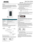
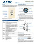
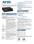
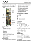
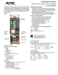
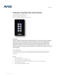
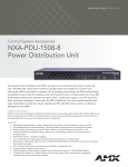
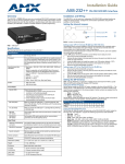
Installation Guide
AXB-REL8 Relay Controller
Overview
Installation
The AXB-REL8 (FG5774) controls closure-activated devices, acting as an eight-channel
relay control port on the AxLink bus.
Setting the DEVICE DIP Switch
Note: Use the DIPSwitch 2.0 application available for free download from AMX to quickly
figure out DIP Switch settings for all types of DIP Switches.
Set the device number on DEVICE DIP switch, located on the front of the AXB-REL8. The
device can be 1 of the 255 devices in an Axcess control system. The device number must
match the device assignment in the Axcess program. Device numbers are assigned into the
following three segments:
• Cards 1 through 95
• Boxes 96 through 127
• Panels 128 through 255
Set the device number by setting the device DIP switches. The device number is the total of
all of the switches in the ON position, and take effect by cycling the power.
DEVICE DIP Switch Settings
FIG. 1 AXB-REL8
Position
1
2
3
4
5
6
7
8
Specifications
Value
1
2
4
8
16
32
64
128
Wiring
Specifications
Preparing and Connecting Captive Wires
Dimensions (HWD)
1.51" x 5.55" x 5.45" (3.84 cm x 14.10 cm x 13.84 cm)
Enclosure
Non-glare, high-impact black matte plastic
1.
2.
Power Consumption
• Baseline draw: 90 mA @ 12 VDC (min)
• With all 8 relays On: 170 mA @ 12 VDC (max)
3.
Weight
17.50 oz. (496.11 g)
Wiring Guidelines
Included Accessories
Metal tab strips included for external adjacent relay communing.
Optional Accessories
AC-RK Accessory Rack Kit
Dimensions (HWD)
1.51" x 5.55" x 5.45" (3.84 cm x 14.10 cm x 13.84 cm)
Enclosure
Non-glare, high-impact black matte plastic
Front Panel Components
AxLink Status indicator
AxLink LED (green and blinks to indicate AxLink
communication activity and power:
• Full-Off indicates no power is being received or the
controller is not functioning properly.
• One blink per second indicates power is active and
AxLink communication is functioning.
• Full-On indicates there is no AxLink control or activity, but
power is On.
Device DIP switch
An eight-position DIP switch is used to set the device
number for the AXB-REL8.
Relay LEDs 1-8 (Red)
Illuminate when associated relay is closed. Relay LED's
should match panel control function.
Rear Panel Components
AxLink connector
Four-pin captive wire receives power and information via
the AxLink bus and AxLink system controller.
Relay contacts
Eight (normally -open) isolated two-pin relay contacts
1 A @ 28 VAC or VDC:
• Relays 1-4 can share a common if use jumper "A" pins
with a tab strip
• Relays 5-8 use discrete commons (wire commons
individually)
Device DIP
switch
Relay
LEDs (1-8)
Strip 0.25 inch of wire insulation off all wires.
Insert each wire into the appropriate opening on the connector according to the wiring
diagrams and connector types described in this section.
Tighten the screws to secure the wires. Do not tighten the screws excessively; doing
so may strip the threads and damage the connector.
The interface requires a 12 VDC power to operate properly. The interface uses a PSN2.8
power supply. The Central Controller supplies power via the AxLink cable or external 12 VDC
power supply.
The maximum wiring distance between the Central Controller and interface is determined by
power consumption, supplied voltage, and the wire gauge used for the cable.
The table below lists wire sizes and maximum lengths allowable between the REL8 and
Central Controller. The maximum wiring lengths for using
AxLink power are based on a minimum of 13.5 volts available at the Central Controller’s
power supply.
Wiring Guidelines at 170 mA
Wire Size
Maximum Wiring Length
18 AWG
690.42 feet (210.43 m)
20 AWG
436.80 feet (133.13 m)
22 AWG
272.33 feet (83.00 m)
24 AWG
171.66 feet (52.32 m)
AxLink Data and Power Connections
Connect the control system's AxLink connector to the AxLink connector on the rear panel of
the AXB-REL8 for data and 12 VDC power as shown in FIG. 3.
PWR +
PWR +
AXP/TX
AXP/TX
AXM/RX
AXM/RX
GND -
GND AXB-REL8
Central Controller
FIG. 3 AxLink wiring
Wiring AxLink With Optional 12 VDC Power Supply
Connect the control system's AxLink connector to the AxLink connector on the rear panel of
the AXB-REL8 as shown in FIG. 4.
PWR (+)
AxLink LED
DEVICE
AXlink
1
2
3
4
5
6
7
8
Local +12 VDC power supply
(coming from the PSN power supply)
GND (-)
ON
Relay contacts 1-4
(shared commons)
Relay contacts 5-8
(discrete commons)
AxLink
connector
AXP
AXM
PWR
GND
8
B
7
A
B
6
A
B
5
A
B
4
A
B
3
A
B
A
B
A
B
PWR +
AXP/TX
AXM/RX
AXM/RX
GND -
GND -
1
2
PWR +
AXP/TX
A
AXB-REL8
Central Controller
FIG. 4 Wiring AxLink with Optional 12 VDC power supply
AXlink
FIG. 2 AXB-REL8 front and rear views
Use a 12 VDC power supply when the distance between the control system and AXB-REL8
exceeds the limits described in the Wiring Guidelines at 170 mA table, or the power supply
current capacity cannot accommodate the 170 ma (max) draw of the AXB-REL8.
• Make sure to connect the GND and +12 VDC wire on the AXB-REL8 AxLink connector
end.
• Do not connect the optional +12 VDC power supply wire to the control system's power
supply side of the AxLink connector (FIG. 4).
Checking The Installation
After set-up is complete:
1.
Check continuity of relay wiring.
2.
Check cable numbers and wiring, interfaces and sources against supplied
documentation.
3.
Install tab strips to jumper between shared commons and clip off excess tabs.
4.
Insert relay wiring terminals into AXB-REL8.
System Worksheet
Relay connections
The relay specification is 1 A @ VAC or VDC. FIG. 5 shows the relay wiring diagram for the
AXB-REL8. The dotted lines are used to indicate commons. Install supplied tab strips to
jumper between shared commons. Clip off excess tabs and bend strip up, away from other
wiring.
1
2
3
4
5
A
B
A
B
A
RELAYS SHARING A COMMON
Jumper "A" pins with tab strip
B
A
B
A
B
A
6
7
B
RELAYS WITH DISCRETE COMMONS
Wire commons individually
A
B
A
8
B
FIG. 5 Relay wiring diagram
Testing The Installation
1.
2.
3.
4.
5.
6.
Check AxLink status LED - it should blink once per second (see Specifications table for
AxLink status LED).
Relay LED lights, but source does not activate:
Check wiring continuity.
Check jumpers used for shared commons.
Check cable and source against supplied documentation.
Check operational status of interface or source.
FIG. 6 AXB-REL8 System Worksheet
Rack-Mounting the AXB-REL8 (optional)
To rack-mount the AXB-REL8 into the optional AC-RK Accessory Rack Kit:
1.
Remove any connected relay and AxLink connectors from the rear panel.
2.
Remove the two screws on the front panel of the AXB-REL8.
3.
Remove the front panel and the space bracket behind the panel.
4.
Place the unit in the appropriate opening in the AC-RK.
5.
Place the front panel of the AXB-REL8 on the front of the rack, over the unit.
6.
Fasten the front panel to the rack and to the unit with the two screws you removed.
For full warranty information, refer to the AMX Instruction Manual(s) associated with your Product(s).
5/12
©2012 AMX. All rights reserved. AMX and the AMX logo are registered trademarks of AMX.
AMX reserves the right to alter specifications without notice at any time.
3000 RESEARCH DRIVE, RICHARDSON, TX 75082 • 800.222.0193 • fax 469.624.7153 • technical support 800.932.6993 • www.amx.com
93-5774-01
REV: A