1
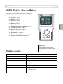
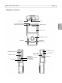
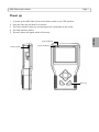
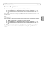
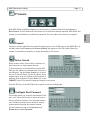
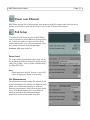
User’s Guide
ENGLISH
AXIS T8414 Installation Display
About this Document
This document includes instructions for setting up and
using the AXIS T8414 Installation Display.
Legal Considerations
Video and audio surveillance can be prohibited by laws
that vary from country to country. Check the laws in
your local region before using this product for
surveillance purposes.
Electromagnetic Compatibility (EMC)
This equipment generates, uses and can radiate radio
frequency energy and, if not installed and used in
accordance with the instructions, may cause harmful
interference to radio communications. However, there is
no guarantee that interference will not occur in a
particular installation.
If this equipment does cause harmful interference to
radio or television reception, which can be determined
by turning the equipment off and on, the user is
encouraged to try to correct the interference by one or
more of the following measures: Re-orient or relocate
the receiving antenna. Increase the separation between
the equipment and receiver. Connect the equipment to
an outlet on a different circuit to the receiver. Consult
your dealer or an experienced radio/TV technician for
help. Shielded (STP) network cables must be used with
this unit to ensure compliance with EMC standards.
USA - This equipment has been tested and found to
comply with the limits for a Class B computing device
pursuant to Subpart B of Part 15 of FCC rules, which are
designed to provide reasonable protection against such
interference when operated in a commercial
environment. Operation of this equipment in a
residential area is likely to cause interference, in which
case the user at his/her own expense will be required to
take whatever measures may be required to correct the
interference.
Europe This digital equipment fulfills the
requirements for radiated emission according to limit B
of EN55022, and the requirements for immunity
according to EN55024 residential and commercial
industry.
Australia - This electronic device meets the
requirements of the Radio communications
(Electromagnetic Compatibility) Standard AS/NZS
CISPR22.
Equipment Modifications
This equipment must be installed and used in strict
accordance with the instructions given in the user
documentation. This equipment contains no
user-serviceable components. Unauthorized equipment
changes or modifications will invalidate all applicable
regulatory certifications and approvals.
Liability
Every care has been taken in the preparation of this
document. Please inform your local Axis office of any
inaccuracies or omissions. Axis Communications AB
cannot be held responsible for any technical or
typographical errors and reserves the right to make
changes to the product and documentation without
prior notice. Axis Communications AB makes no
warranty of any kind with regard to the material
contained within this document, including, but not
limited to, the implied warranties of merchantability
and fitness for a particular purpose. Axis
Communications AB shall not be liable nor responsible
for incidental or consequential damages in connection
with the furnishing, performance or use of this material.
RoHS
This product complies with both the European
RoHS directive, 2002/95/EC, and the Chinese
RoHS regulations, ACPEIP.
WEEE Directive
The European Union has enacted a Directive
2002/96/EC on Waste Electrical and Electronic
Equipment (WEEE Directive). This directive is
applicable in the European Union member
states.
The WEEE marking on this product (see right) or its
documentation indicates that the product must not be
disposed of together with household waste. To prevent
possible harm to human health and/or the environment,
the product must be disposed of in an approved and
environmentally safe recycling process. For further
information on how to dispose of this product correctly,
contact the product supplier, or the local authority
responsible for waste disposal in your area.
Business users should contact the product supplier for
information on how to dispose of this product correctly.
This product should not be mixed with other commercial
waste.
Support
Should you require any technical assistance, please
contact your Axis reseller. If your questions cannot be
answered immediately, your reseller will forward your
queries through the appropriate channels to ensure a
rapid response. If you are connected to the Internet, you
can:
• download user documentation
• find answers to resolved problems in the FAQ database.
Search by product, category, or phrases
• report problems to Axis support by logging in to your
private support area.
AXIS T8414 User’s Guide
Page 3
AXIS T8414 User’s Guide
This user’s guide provides instructions for using the
AXIS T8414 Installation Display.
Overview - page 4
Battery - page 6
Power up - page 7
Viewing Images - page 8
Menus - page 10
Setup - page 15
Connect to a network camera - page 11
Snapshot function - page 17
Network cable test - page 12
AV in - page 12
System setup - page 20
Alternative connection methods - page 21
Technical Specifications - page 22
ENGLISH
•
•
•
•
•
•
•
•
•
•
•
•
•
Important!
This product must be used in
compliance with local laws and
regulations.
Package contents
Item
Models/variants/notes
Installation Display
AXIS T8414
Power supply with power cable
12 V DC Adapter
Battery
7.4V Li-ion Battery Pack 2200mAh
Cables
•
BNC Cable
•
Network Cable
Printed materials
Included accessories
AXIS T8414 User’s Guide (this document)
•
Soft carrying case
•
Terminator block
•
Car charger
Page 4
AXIS T8414 User’s Guide
Overview
AXIS T8414 is a battery-powered, handheld device that greatly simplifies the installation of both
Axis network cameras and analog cameras. It displays live video from a camera and makes setting a
camera’s viewing angle and focus at the installation site easier than with the use of a laptop or
remote computer. It offers user-friendly features such as touchscreen, zoom and snapshot
functions. AXIS T8414 can connect directly to a camera, or to a network, and search for Axis
network video products. An Axis camera with built-in PoE support can even be powered directly by
AXIS T8414, giving installers greater flexibility.
•
•
•
•
•
Simplifies setting the camera's viewing angle and focus
The live video display and zoom functions help installers to adjust the field of view and set
and test the camera focus.
Power over Ethernet for powering cameras
AXIS T8414 delivers PoE to Axis network video products with PoE support either from the
unit's battery or from PoE by-pass. This allows network cameras with PoE to be powered
up and tested without extra tools or the need for electricity and network infrastructures at
the installation site.
User-friendly
AXIS T8414 Installation Display has user-friendly functions that greatly simplify camera
setup. For example, the touchscreen monitor is simple and convenient to use at awkward
installation locations. Full zoom in the image is via a simple tap on the touchscreen.
Snapshot function
AXIS T8414 allows installers to take snapshots of images the network camera delivers as
proof of finalized installation. The snapshots from network cameras can be saved to USB,
Micro SD card, or AXIS T8414.
Supports both Axis network video products and analog cameras
AXIS T8414 Installation Display supports Axis network cameras and encoders, as well as
analog cameras through a BNC connector. AXIS T8414 is shipped with both an Ethernet
cable and a BNC cable.
AXIS T8414 User’s Guide
Page 5
Hardware overview
Stylus slot
AV in
Data indicator LED
Power indicator LED
ENGLISH
Light sensor
LCD screen
Navigation keys
Start/Enter
Snapshot key
ESC key
POWER on/off
Power bank on/off
LAN/PoE OUT
USB slot
CAT5 Cable
tester port
LAN/PSE IN
(External power bank
not included)
Micro SD slot
Charging LED
DC12V
Page 6
AXIS T8414 User’s Guide
Unit connectors
LAN/PoE OUT - RJ-45 Ethernet connector. Provides power to network cameras that are PoE
enabled.
LAN/PSE IN - The Power bank provides 48 V DC power (External power bank not included).
USB slot - Connect USB storage devices for data storage.
Micro SD slot - Insert a Micro SD card into the slot for data storage.
AV in - BNC connector for connecting an analog camera. Use a 75 ohm coaxial video cable.
CAT5 Cable tester - for testing and detecting wiring types. See Network cable test, on page 12 for
instructions on testing wiring type.
Power Adapter - 12 V DC connector.
LED indicators
LED
Indication
Power
Power on indicator.
Data
Flashes when the AXIS T8414 is under operation
Charging
The LED will stay lit while the AXIS T8414’s battery is charging.
Battery
The AXIS T8414 is powered by a rechargeable Li-ion battery pack that takes approximately 4 hours
to charge, and provides the AXIS T8414 with up to 3 hours run time.
To open the battery compartment cover, press it while sliding it
outward, as shown in the figure below.
When installing the battery, make sure that it is oriented correctly
as shown in the figure.
During the charging process, the charging indicator will be lit.
AXIS T8414 User’s Guide
Page 7
Power up
1.
2.
3.
4.
5.
To power up the AXIS T8414, first set the Power switch to the “ON” position.
Press the Start key and hold for 3 seconds.
The Power indicator lights up. and a progress bar is displayed on the screen.
The Data Indicator flashes
The main menu will appear within 45 seconds.
ENGLISH
Data indicator
Power switch
Power indicator
Start key
Page 8
AXIS T8414 User’s Guide
Viewing images
With AXIS T8414 Installation Display you can connect to a camera either through Connect or
Device Search for viewing images, see Connect and Device Search, on page 11. The default view
from the camera is at a relatively low resolution. When zooming into the view (see Digital zoom
below) the camera's own default resolution is used instead, to provide greater detail.
Press the ESC key on the AXIS T8414 front panel at any time to exit the viewing screen.
Digital zoom, PT mode, and Flip view all cameras
Zoom - Tap ZOOM on the screen for digital zoom. This
will show the image at the camera's own default
resolution, to allow fine adjustment of the focus.
PT Mode - While digitally zoomed into the view from the
camera, the navigation keys can be used to move around
in the image. The letters PT (Pan/Tilt) indicate that this is
enabled. The arrows and digits at the bottom of the
screen indicate the current position.
Up
R
L
Down
ESC
Flip view - Press and hold the Up and Down navigation
keys to flip the view 180 degrees. Press again to flip back
again.
DC-Iris cameras
If the camera has a DC-Iris, this can be disabled for focusing by holding down the L and R
navigation keys at the same time. Repeat to enable the DC Iris again.
Remote focus cameras
For cameras that support remote focus, this is controlled by the following:
Press and hold the L and R navigation keys to start the focus procedure. This also
automatically disables the DC-Iris. Press and hold the L and R keys again to re-enable the
DC-Iris.
• Press and release the L or R key for single small focus steps.
• Press and hold the L or R key for continuous large focus steps.
When digitally zoomed into the image, tap the ZF (Zoom/Focus) indicator/switch to switch to PT
(Pan/Tilt) mode.
•
AXIS T8414 User’s Guide
Page 9
Cameras with optical zoom
For cameras that support optical zoom, this is controlled by the following:
Press and hold the Up or Down navigation key for continuous optical zoom, in or out.
Press and release the Up or Down navigation key for optical zoom in single steps, in or
out.
When digitally zoomed into the image, tap the ZF (Zoom/Focus) indicator/switch to switch to PT
(Pan/Tilt) mode.
•
•
When connected to a mechanical PTZ camera, the PTZ functions can be controlled by the following:
•
•
•
Tap the direction arrows on the screen to pan and tilt the view.
Press and hold the Up or Down navigation key for continuous optical zoom, in or out.
Press and release the Up or Down navigation key for optical zoom in single steps, in or
out.
Tap ZOOM on the screen for digital zoom, which will show the image at the camera's default
resolution. Since the camera has mechanical Pan/Tilt functionality, the digital PT mode is not
available.
ENGLISH
PTZ cameras
Page 10
AXIS T8414 User’s Guide
Menus - Main menu
Button
Function
Main Menu.
Return, go to previous page.
Enter, opens a submenu or saves
settings.
PoE indicator
Battery status
Connect to an Axis network
camera.
View analog camera connected
to AV IN connector
CAT5 Network cable test
PoE On/Off
PoE Setup
Setup menu
AXIS T8414 User’s Guide
Page 11
IP Camera
Connect
Connect a network cable from the camera’s network port to one of LAN ports on the AXIS T8414. In
the Main menu tap IP camera and Connect. Waiting will appear on the LCD display. When the
camera is connected successfully, its image will display in the screen.
Device Search
Device search can be used to find all cameras in a
local network or a single camera directly.
To find cameras on a local Network, connect AXIS
T8414 to the LAN with a network cable from one of
the LAN ports. Tap the Device Search icon to show
the list of cameras found. Tap the IP address of the
target camera, enter its Username and Password if
different from the default. Tap the Enter icon or the
CONNECT button. The camera’s image will display in the screen.
Press the ESC key on the AXIS T8414 front panel to exit the viewing page.
Configure Root Password
This setting allows you to specify a password for the
user ‘root’, which will be used to access all new or
factory defaulted cameras. If an individual camera
uses a different password, this should be directly
entered when accessing that camera instead.
Use the keyboard to tap in the Username and
Password and tap Set Password.
ENGLISH
With AXIS T8414 Installation Display you can connect to a camera either through Connect or
Device Search. If the IP address for the camera is not the default address expected, AXIS T8414 will
change its own IP address to enable the connection. This may take a few seconds to complete.
Page 12
AXIS T8414 User’s Guide
AV In
Video in
Test analog video by connecting the BNC cable from the camera's video output to the AXIS T8414
video input port. Tap the AV In icon in the Main Menu, and the video signal will be displayed on the
LCD screen. Press the ESC key to return to the menu.
To adjust the contrast in the image, go to Setup > Setup AV.
Network cable test
Follow these steps to test a network cable for
type; straight or cross, and for errors; open,
short or miswire.
1. Connect one end of the network cable to
the supplied CAT5 Network terminator and
the other end to the CAT5 port.
2. Tap the CAT5 icon in the Main menu
3. The cable's wire map will be displayed on
the screen.
AXIS T8414 User’s Guide
Page 13
Power over Ethernet
AXIS T8414 delivers PoE to Axis network video products with PoE support either from the unit's
battery or from PoE by-pass. Tap this icon to turn on and off Power over Ethernet.
PoE Setup
Power Level
The output Power Consumption Level range can be
set according to different needs. The options include
<Very Low (~3W)>, <Low (3~5W)>, and Mid-High
(6~25W+EXT 12V)>.
Note:
Please make sure the PoE function is set to Off
before changing the Power Level setting.
PoE Measurement
The information includes voltage (V), current (I) and
power consumption (P) of Power over Ethernet (PoE)
which can be measured according to different
Ethernet circumstances. Select from the drop-down
list of <PoE Measurement> to fit your Ethernet
condition and show the PoE Measurement
information on the screen while using PoE.
ENGLISH
To enable that PoE starts as soon the AXIS T8414
itself is powered up, select ON from the drop-down
list. To limit the amount of time that PoE will be
enabled when there is no camera connected, select
the number of seconds from the PoE autoshutdown after drop-down list.
Page 14
PoE Measurement Display
Select the desired combination of PoE Measurement
information from the drop-down list, including
Voltage (V), Current (I), and Power Consumption (P).
Enable PoE after Tester Bootup
To enable PoE while the Tester is booting up, please
select <ON> from the drop-down list of <Enable
PoE when booting>.
The Tester will provide power to the camera right
after system startup.
PoE Auto-shutdown
Set the PoE auto-shutdown interval to 20 seconds,
40 seconds or 60 seconds. The setting will help save
battery when there is no network camera or other
device using the Tester as the PSE. A reminder will
show 5 seconds before shutting down.
Tap <Enter/Save>
to save all the settings and
you will then automatically be directed to the Home
Screen. Or tap <Return>
to exit the setting page
without saving settings.
AXIS T8414 User’s Guide
AXIS T8414 User’s Guide
Page 15
SETUP
Under SETUP are the menus for IP, AV, System, and Snapshot
ENGLISH
Setup - IP
Setup - IP connection
These settings are optional and advanced. In most
situations the you will not need to change them.
The settings that cannot be changed are intended
for future use. Leave other settings as they are,
unless specifically required.
1. Tap the Setup- IP connection icon. Enter the
information in each field using the stylus.
AXIS T8414 - The IP address can be set to DHCP or to a fixed address. DHCP is the default setting and should be used in most situations, even when there is no actual DHCP server available
via a network. The IP address is grayed out when set to DHCP. To set a fixed address, tap Set,
change the IP address and then tap the Enter icon.
Camera Profile - this allows you to store camera configurations so that they can be recalled
later. Select a profile from the list, or change the name and settings.
Camera IP - enter the network camera’s IP address.
Page 16
AXIS T8414 User’s Guide
Camera Type- AXIS Camera (by default)
User Name - enter the user name for the camera. By default Axis’ products have “root”
Password - enter the password for the camera. By default Axis’ products use “pass”. To reveal
the password being entered, tap Show.
Management Port, Streaming Port, Streaming Format, and Streaming Protocol can be left at
their default settings unless the camera has been set up with different settings.
2. To save a new camera profile, make changes and tap the “+” key. To delete a camera profile,
find it in the list and tap the “-” key.
3. When finished, tap the Enter button and tap the Return button.
Note: If AXIS T8414 detects a camera with an IP address on a different subnet it will
automatically change its own address so that a connection becomes possible.
Setup - IP camera
These settings are advanced and not normally
required. To make particular settings for an
individual camera, tap the IP camera icon and
enter the network setting of a network camera.
Import Camera Type - used to import a text file
containing camera configuration information from
a USB memory stick.
Load from Camera - Load the current camera configuration, which can then be modified and
reloaded to the camera, using Set to Camera.
Setup - AV
Tap the Setup - AV icon to open the Video Display setup page, from where you can adjust video
brightness, sharpness and contrast. Use the up or down keys on the AXIS T8414 front panel to move
among the items, or tap the icon on the right-side of the value indicator. To adjust the value, press
the left/right keys on the front panel or tap the slider in the page.
Tap the Enter icon to save the settings.
Tap this icon to switch between
brightness, sharpness and contrast
AXIS T8414 User’s Guide
Page 17
Snapshot Function
Snapshot key
Edit
Once the Snapshot key is pressed, the Snapshot
editing page will open. Choose a location to store
the snapshot by tapping on T8414, USB or SD.
1. Enter a file name and description.
2. Tap Enter/Save icon and return to the viewing
page.
File management
To manage snapshot files from the Main Menu tap
the SETUP icon > Setup-Snapshot. Here you can
preview, copy and delete images.
1. To view files, select the correct Display Path,
T8414, USB or SD.
2. Available snapshot files are listed under File List.
3. To view a snapshot, tap the file name in the list
and the image will appear in Image Preview.
• Copy - Tap the Copy icon, select the
location, and tap Save.
Copy Delete Select all
• Delete - Select the file to remove and tap
the Delete icon. Tap OK to complete the
removal.
• Select all - To select all files for copying or deleting tap the Select all icon.
ENGLISH
In the IP Camera viewing mode, press the Snapshot key on the AXIS T8414 front panel to save the
current image
Page 18
AXIS T8414 User’s Guide
Video Recording
The Tester supports Video Recording, Video Setup, Video File Management and Video Playback
function for camera live views when necessary.
Implement Video Recording
In the camera’s live view mode, tap the text “REC” on
the right top corner of the live view screen to start
Video Recording. During the recording process, the
text will be in red. Tap the text “REC” one more time
to stop Video Recording.
Video Recording Setup
(Video- Rec Setup)
Tap the <Setup>
icon on the Home Screen to
enter the Video Recording Setup screen. Enter
<Setup - Video> by tapping the icon.
Tap <Video - Rec Setup> on the Video Setup Screen
to access video recording setup page.
AXIS T8414 User’s Guide
Page 19
Assign a storage location (Tester/ USB/ SD) located
on the top of the setup page and save the videos by
tapping the radio button to the left side of the
selected option. Enter the file name and description
for the snapshot.
Tap <Enter/Save>
to save all the settings and
return to the live view mode, or tap <Return>
to exit the setting page without saving settings.
Preview, copy and delete video on the <VideoPlayback> page. Tap the <Setup>
icon on the
Home Screen and tap on <Setup- Video>
to
enter the Video Setup Screen. Then tap on <VideoPlayback> to access video play back page.
Video Playback
On the <Setup-Snapshot> page, select the recording
video storage path (Tester/ USB/SD). Then all the
video files will be listed in the <File List> field. To
view a video, tap the file name in the list and tap the <Playback> button on the bottom, the video
will appear as full screen.
In the Video Playback mode, press the <ESC>key on the Tester (see Hardware overview, on page 5)
to stop playback and return to video playback page.
Single File Copy
Tap the file name in the list to Copy, and then tap the < Copy> icon in <File Manager> section
below <Image Preview>. Select the location to copy the file to in the pop out window, and then tap
<Enter/Save>
ENGLISH
Video Playback
Page 20
AXIS T8414 User’s Guide
All Files Copy
Tap the <Select All> icon in <File Manager> section below <Image Preview> to select all the files
in <File List>. Then tap the <Copy> icon to copy all the files. Select the location to copy the files to
in the pop out window, and then tap <Enter/Save>
Single File Deletion
Tap the file name in the list to delete then tap the <Delete> icon in <File Manager> section below
<Image Preview>. Tap <OK> on the pop out window to allow file deletion.
All Files Deletion
Tap the <Select All> icon in <File Manager> section below <Image Preview> to select all the files
in <File List>. Then tap the <Delete> icon to delete all the files. Tap <OK> on the pop out window
to allow all files deletion.
System Setup
Tap the Setup-System icon to enter the AXIS T8414
System setup page. In this page, you can adjust the
brightness of the screen, implement firmware
upgrades and restore all settings of the AXIS T8414
to factory default.
Backlight Adjustment - Control the brightness of
the AXIS T8414 screen by moving the slider of the
Backlight value indicator. A higher value produces a
brighter image.
Firmware Upgrade - When you upgrade your AXIS
T8414 with the latest firmware from the Axis Web
site, your Installation Display receives the latest functionality available. Always read the upgrade
instructions and release notes available with each new release, before updating the firmware.
1. Save the firmware files (*.tgz, *.tgz.md5) to a USB device in a folder named
upgrade\upd_t8414s.
2. Tap the Upgrade button, to open the File Select dialog.
3. Tap the USB button and select the firmware upgrade file.
4. Tap the Enter icon.
Complete Update - Check this option if you would like a complete installation of every component
in the firmware. If this option is not checked, only the changes in the firmware will be upgraded.
Restore to Factory Defaults - Restore the AXIS T8414 system to factory default by tapping the
Default button,
AXIS T8414 User’s Guide
Page 21
Auto Shutdown - To save power, tap the drop-down list to choose the amount of idle time before
AXIS T8414 shuts down.
Alternative connection methods
External powerbank
Connect a camera to PoE out, connect a powerbank to PSE IN, set the Powerbank’s switch to the
ON position.
ENGLISH
Page 22
AXIS T8414 User’s Guide
Technical Specifications
Function/
group
Item
Specification
Model
AXIS T8414 Installation Display
Color LCD Field Display
3.5 inches
Resolutions
320x240
Video
Image settings
Autosensing
Network
IP Setting
• Static IP address
• DHCP
General
Casing
ABS plastic
Memory
128 MB RAM (16 MB available for snapshots)
Power
• 12 V DC +/- 10%, 1 A
• CANON BP-915 (7.4 V 2000 mAh)
80% capacity after 300 charge cycles
Charge time 3.5 Hrs
Operation time 3 Hrs with PoE off, 2 Hrs with PoE
on.
Connectors
• BNC Video in
• RJ-45 10BASE-T/100BASE-TX PoE IEEE 802.3af
• CAT-5
• USB 2.0
• PoE
Operating conditions
0 – 50 °C (32 –122 °F)
Humidity 20 - 80% RH (non-condensing)
Local Storage
SD/SDHC memory card slot (card not included)
Approvals
• USA/FCC Class B
• Europe/CE Class B
• Australia/ C-tick Class B
Dimensions (HxWxD)
170 x 99 x 38 mm
(6.7” x 3.9” x 1.5”)
Weight
450 g (0.99 lb.)
Included accessories
• Soft carrying case with sunshield
• Protective rubber sleeve
• Built-in stylus
• Terminator block for CAT-5 Cable test
• CAT5 Network cable
• BNC cable
• Car charger 12 V DC
• Power supply
Display
User’s Guide
AXIS T8414
© Axis Communications AB, 2012
Ver.1.00
Printed: January 2012
Part No. 45360