1
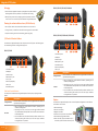
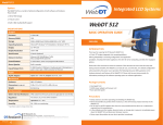
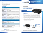
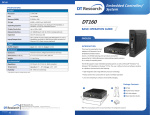
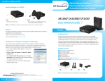
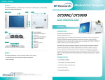
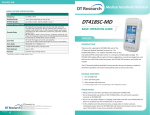
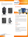
Integrated LCD Systems
Integrated LCD System
Mounting
The DT Research Integrated LCD System is designed to be secured to VESA-compliant mounting
arms or stands. This is accomplished by equiping the standard metal base on the rear of the display
unit. The VESA-compliant mounting holes at the rear of the device will mate with VESA mounts or
arms to meet the requirements of the deployment.
BASIC OPERATION GUIDE
ENGLISH
1. Remove the detachable base by pressing
upward to remove the cover, then unscrewing
the four screws attaching the base to the
display.
2. The display without the base.
INTRODUCTION
Thank you for acquiring the DT Research Integrated LCD System, a 15-inch/ 17-inch/ 19-inch/
21.5-inch TFT display-integrated, thin computing platform, offering adaptability to mounting
configurations and applications, including information appliance, thin client for server computing,
and disk drive-equipped options.
Please take a few moments to review the contents of this document to ensure that the setup and
startup proceed smoothly. The DT Research Integrated LCD System is ready for use, out of the box,
in its default configuration when powered by the power source provided. The following discussion
offers guidance on the hardware elements and features of the DT Research Integrated LCD System.
Please refer to your device provider for information pertaining to the software operating system or
software applications.
3. Attach the new VESA-compliant mounting
device or stand to the display.
4. The display successfully mounted on a
VESA-compliant mounting arm.
Package Contents
• One DT Research Integrated LCD System
• AC/DC power adapter with power cord
• Basic operation guide
Precautions
• Always exercise care when operating and handling the DT Research Integrated LCD System.
• Never disassemble any portion of the enclosure, as this will void any product warranty on the
DT Research Integrated LCD System.
• Do not use any AC/DC adapter other than the one provided with the device or a replacement
acquired from the manufacturer.
• In the unlikely event that smoke, abnormal noise, or strange odor is present, immediately power
down the DT Research Integrated LCD System and disconnect all power sources. Please report
the problem to your device provider immediately.
DT Research, Inc.
2000 Concourse Drive, San Jose, CA 95131 http://www.dtresearch.com
4
ENGLISHsignage dtri com
Copyright © 2012, DT Research, Inc. All Rights Reserved. DT Research is a registered trademark of DT Research, Inc.
BOG050412ILENG
Integrated LCD Systems
Packaging
DT515D/ DT517D/ DT519S/ DT519S-MD
• The DT Research Integrated LCD System is packaged with recyclable materials
and designed for maximum protection in transportation and handling.
• When possible, please save the packaging carton and protective inserts for
re-use if there is ever a need to ship the DT Research Integrated LCD System.
Cleaning the anti-microbial enclosure (DT500 MD series)
1
2
3 4
5
6
7
• Use a soft/non-abrasive cloth moistened with water to clean the enclosure.
8
• If using a cleaner, an alcohol-free and oxide-free cleaning liquid is recommended.
• To prevent scratching the anti-microbial coating, please wipe gently.
DT522D/ DT522S/ DT522D-MD/ DT522S-MD
9
I/O Panels & Function Buttons
The DT Research Integrated LCD System has a comprehensive set of I/O ports. The following ports
are located along the lower rear edge of the display unit.
8
DT517C/ DT519C
1
8
1
2
3 4 5
6 7
1. Two USB 2.0 ports
2. COM ports
3. Audio-out jack
4. Microphone-in jack
5. Line-in jack
6. Ethernet port (RJ45)
7. DC-in jack
8. Two USB 2.0 ports
9
The four buttons are intended to be user programmable via software in
applicable operating systems.
10. Power
• May be configured to perform different functions, depending on the
software operating system.
• Depending on the OS, a brief, firm push will trigger software-enabled
entry into Shutdown or Standby modes. Push in similar manner to Restart or
to exit Standby mode.
• Push and hold for over 4 seconds to forcefully shut down the device. This
method of powering off should only be used when proper shutdown
through software is not possible.
ENGLISH
2
6
7
9
8. Programmable
The three buttons are intended to be user programmable via software in
applicable operating systems.
9. Power
• May be configured to perform different functions, depending on the
software operating system.
• Depending on the OS, a brief, firm push will trigger software-enabled
entry into Shutdown or Standby modes. Push in similar manner to Restart or
to exit Standby mode.
• Push and hold for over 4 seconds to forcefully shut down the device. This
method of powering off should only be used when proper shutdown
through software is not possible.
The side panel of the DT Research Integrated LCD System features power, and programmable
buttons.
9. Programmable
5
Description
Side Panel Function Buttons
Description
3 4
Button
10
Button
2
1. Two USB 2.0 ports
2. COM ports
3. Audio-out jack
4. Microphone-in jack
5. Two USB 2.0 ports
6. Ethernet port (RJ45)
7. DC-in jack
Options
The DT Research Integrated LCD System has a number of optional configurations in both software
and hardware. These include:
1. SSD or HDD storage
2. IR touch screen display
3. Magnetic card reader
4. Presence sensor and scanner auto detection
5. Built-in 802.11a/b/g/n WLAN module
6. Smart card reader; supports ISO 7816 T=0, T=1
smart card, 3V/ 5V smart card and memory card
3
ENGLISH