Transcript
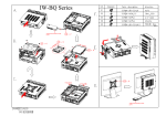
Installation Guide
(Please read the following steps to assemble)
Please note that the pictures in this installation guide are for
your reference only, and they may vary from the actual
product.
1
2
6
5
4
3
2
7
8
1
Front Panel Header
9
IEEE 1394 Header
USB Header
HD Audio Header
AC'97 Audio Header
12
11
10
Red
White
TPA1+
1
2
TPA1-
Reset SW
Orange
White
Ground
3
4
Power SW
Brown
White
TPA2+
5
+12V
7
H.D.D. LED
+
-
+
-
+
Power LED
Blue
Power LED
Blue
-
White
+
-
White
+
Key (no pin)
-
VCC (+5V)
R
(Red)
(MIC) Port 1L
1
2
Ground
Ground
MIC
1
2
AUD_Ground
D-
W
(White)
(MIC) Port 1R
3
4
Presence#
MIC Bias
3
4
AUD_Ground
6
TPA2-
D+ G
(Headphone) Port 2R
5
6
Sense1_Ret FP_Out_R
5
6
FP_Return_R
8
+12V
Sense_Send
7
Key (no pin)
No use
10
Ground
9 10
Sense2_Ret
FP_Out_L
GND
BK
(Green)
(Black)
(Headphone) Port 2L
Key (no pin)
9 10 FP_Return_L
【 O p e n i n g t he Chassis 】
1.Remove Top Cover:
Unlock the screws and remove top
cover. 1 2
2.Remove Front Panel:
Unlock the locking tabs and remove front
panel. 3
3.Remove ODD Cage:
Unlock the screws. 4
Pull up and remove ODD Cage. 5
4.Remove Partition:
Pull up and remove the partition plate. 6
5.Remove HDD Cage:
Unlock the screws. Pull the HDD Cage to
the front and remove HDD Cage. 7 8
13
14
20
【 M o t h e r b o ard Installation 】
15
21
27
16
22
28
17
23
29
19
18
24
25
26
30
6.Please follow M/B Installation Guide to
connect power cables to M/B. Equip IOshield, Motherboard, CPU, Memory and
heat sink. 9
【Front I/O Wires Installation】
7.Connect all cables to M/B. (Included USB,
1394, HDD LED, HD Audio, Power Switch,
Power LED, Reset Switch…) (IEEE1394 is
an optional feature.) 10 11
【 E x t e r n a l HDD Installation 】
8.Equip HDD drive into the HDD cage. Slide
HDD cage into the HDD bay. 12 13
9.Connect cables to the HDD drive. Secure
it with screws. 14
【External 3.5” Card Reader Installation】 【ODD (5.25” drives) Installation】 【Add-On (PCI/AGP) Card Installation】
10.Slide 3.5” Card Reader drive into the 3.5”
drive bay. 15
11.Connect cables to the Card Reader drive.
Secure it with screws. 16
【 Partition Installation 】
12.Equip Partition on the chassis. Make
IDE and Power cables through partition.
17 18
13.Adjust the position of ventilation hole
according to the CPU fan location. 19
14.Slide ODD ROM into the ODD cage.
Equip ODD cage onto the chassis.
Remove Filter from ODD cage. (Filter is
an optional part.) 20 21
15.Connect IDE and Power cables to
ODD ROM. Equip Filter on ODD cage.
(Filter is an optional part.) 22 23
16.Secure the position with screws from
the front. 24
17.Pull up the I/O slot screw cover and
unlock the screws. Remove the I/O slot
cover. 25 26
18.Equip Add-On cards. 27
19.Lock the screws and close the slot screw
cover. 28
【Panels Installation】
22.Install the front panel. 29
23.Slide the top cover back to the chassis
and secure it with screws. 30
【Installation Completed】