1
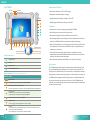
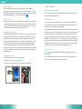
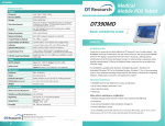
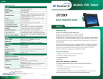
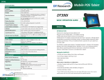
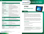
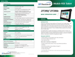
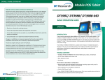
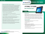
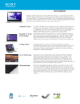
DT390MD
Medical
Mobile POS Tablet
SPECIFICATIONS
System
Processor
Memory (RAM)
Storage
Intel® Atom™ Z530, 1.6GHz
2GB DDR2 533MHZ
2GB to 32GB Flash
Operating Systems
Microsoft® Windows® Embedded Standard 7, Windows® 7
Professional, Windows® XP Embedded; Windows® XP Pro
for Embedded Systems, or Linux
Display
8.9” LED-backlight screen with resistive touch; sunlightreadable LCD option
Display Resolution
1024 x 600 (WSVGA)
Network Interface
Wi-Fi 802.11a/b/g/n, Bluetooth 2.1 with EDR
Trusted Platform Module
Yes, TPM 1.2 support
Control Switch and Buttons
Indicator
Speaker/Microphone
1 power button, 7 front buttons and 1 trigger button
Input/Output Ports
1 DC-in Jack; 1 USB 2.0 ports; 1 Headphone-out Jack
combined with microphone, 1 Full Slot Smart Card Reader
Full Slot Smart Card Reader
Reads ISO 7816 T=0, T=1; EMV 2000 certified, 1.8/3/5V
smart card
Power
AC/DC Adapter
Built-in speaker; built-in internal microphone
Internal 7.4V, 3760mAh/
Optional: External 7.4V, 3760mAh/ 7.2V, 3900mAh
Mechanical
Enclosure
Stylus
Protective Bumpers
Dimensions (H x W x D)
Weight
ABS + PC plastics
Non-electronic tip
Rubber bumpers on each corner for handling protection
7.7 x 10 x 1.25 in/ 196 x 256 x 32 mm
Vibration and Shock Resistance
Regulatory
2.43 lbs/ 1.1 kg
Thank you for acquiring the latest addition to DT Research’s line of mobile tablets— the
DT390MD. Featuring an IP64-rated, slim yet robust enclosure, the two-pound DT390MD
with 8.9” TFT display is powered by the Intel® Atom™ processor, offering optimal
combinations of performance and power savings. An external battery expansion option
provides approximately 3-4 hours of additional battery operation for up to eight hours
of mobile usage.
The DT390MD is available with Windows® Embedded Standard 7, Windows® XP
Embedded, Windows® XP Pro for Embedded Systems, Windows® 7 Pro or Linux operating
systems. Each software operating system features web browser, client/server computing
software, media player, accessories, and applications support.
PACKAGE CONTENTS
IP64 * IP64 rating may not be applicable for units with module
• Basic Operation Guide
options
• Handstrap
MIL-STD-810G
Major options, depending on configuration:
FCC Class B, CE, C-Tick, RoHS compliant
Operation: -20°C - 40°C
Storage: -20°C - 60°C
Humidity
0% - 90% non-condensing
• Desktop Charging Cradle with DC-in Power Jack and Ethernet/ USB Ports
• X-handstrap
• External External Battery Pack and Battery Charger Kit
• Vehicle/ Wall Mount Cradle
* Specifications subject to change without notice.
* If your DT390MD contains MSR, half-slot smart card reader, RFID reader, camera, 3G or scanner
module, please refer to the POS module operation guide for detailed operation.
DT Research, Inc.
2000 Concourse Drive, San Jose, CA 95131
http://www.dtresearch.com
Copyright © 2012, DT Research, Inc. All Rights Reserved.
DT Research is a registered trademark of DT Research, Inc.
8
INTRODUCTION
• AC-DC Power Adapter with Power Cord
Temperature
ENGLISHsignage dtri com
ENGLISH
• DT390MD with Internal Battery Pack, Stylus and Bumpers
Environmental
Water and Dust Resistance
BASIC OPERATION GUIDE
1 power/ battery status LED and 1 WLAN active LED
Input: 100 – 240V AC; Output: 18.5V DC, 3.89A
Battery Pack
DT390MD
BOG030612DT390MDENG
DT390MD
The DT390MD
Power/Battery LED Status:
Microphone
Wireless LED
Battery/Power LED
• Blue indicates the battery is 25% to 100% charged
• Blinking blue indicates the battery is charging
Stylus
8
D
• Orange indicates that the battery is between 11% to 25%
• Blinking orange indicates that the battery is below 10%
9
Precautions
A
• Always exercise care when operating and handling the DT390MD.
B
• Do NOT apply excessive pressure to the display screen.
C
• We recommend using the Stylus provided to keep the screen clean.
• Avoid prolonged exposure of the display panel to any strong heat source. Wherever
possible, the DT390MD should face away from direct light to reduce glare.
1
2
3
4
5
6
7
Button Management
Calibration
Battery and Power Meter
Wireless Network Settings
Input/ Output Ports
A
Headphone Jack
B
USB Port
C
DC Power Input
D
Full Slot Smart Card Reader
Button Functions (with Windows XP Operating System)
BUTTON
1
ENGLISH
2
3
ACTION
Programmable
4
Programmable, launch soft (on-screen) keyboard (default)
5
Launch SAS (Secure Attention Sequence)
Generate Ctrl+Alt+Del keys to invoke the security windows defined under Windows XP
6
Programmable,
Calibrate touch screen before log on the operating system
Change display orientation (portrait/ landscape) (default)
7
Programmable, system utility menu (default)
8
Programmable,
As scanner trigger when equipped with the scanner module
9
Power on,
Push/release typically enters Standby mode, or Push/release exits Standby mode or
restarts device (software dependent)
Push and hold (over 4 seconds) invokes hardware shutdown
2
• If the AC-DC power adapter is used to recharge or power the device, do NOT use any
AC-DC adapter other than the one provided with the device or acquired from the
manufacturer or its partners.
• In the unlikely event that smoke, abnormal noise, or strange odor is present,
immediately power off the DT390MD and disconnect all power sources. Report the
problem to your device provider immediately.
• Never attempt to disassemble the DT390MD, as this will void the warranty.
Basic Features
The DT390MD wireless tablet integrates a bright and responsive touch display, 1 USB
port, and embedded networking elements such as wireless LAN or optional 3G. The
primary device is complemented by a suite of accessories, including battery expansion,
docking cradles, and wall/ vehicle mount cradles, for a comprehensive user experience.
A DT390MD typically integrates an 802.11a/b/g/n wireless LAN (WLAN) adapter that
may connect to other wireless devices or access points. If your DT390MD does not
come with such a network adapter, please consult your device provider to establish the
desired network connectivity.
3
ENGLISH
DT390MD
OPERATION
Internal Battery
Warning! !
The Internal battery pack should only be replaced by an authorized DT Research service
representative. Please contact your product and/or service provider for internal battery
replacement service.
Powering ON and OFF
To activate the DT390MD, push and quickly release the Power Button. The display will
come on in a few seconds. To put the DT390MD in Standby mode, push and quickly
release the Power Button. To turn the DT390MD off for extended storage, power off the
device safely using any software function that “shuts down computer” provided in the
software operating system.
NOTE: The battery packs shipped with your device may be low in power—please use
the AC-DC adapter with the DT390MD when setting up the device for the first time to
fully charge the internal battery pack. You may charge the external battery pack with it
attached to the DT390MD, or with the optional external battery charger kit.
NOTE: When the battery pack(s) is (are) charging, the blue-colored Battery LED should
blink slowly. If plugging in the AC-DC adapter does not trigger this blinking activity
and the LED stays dark, the battery pack(s) may have been drained substantially. Try
unplugging/ replugging the AC-DC adapter to the DT390MD a few times to activate the
charging process.
NOTE: To conserve power, use (push and quick release) the Power Button to put the
device in “Standby” mode while not in use. Pushing briefly on the same button will wake
up the system within seconds.
NOTE: Avoid using the Power Button (“hold 4+ seconds” feature) to turn off the
device—this form of hardware shutdown is intended to be a means of recovery from
device lockups, and not as normal operation.
Start Up
If the power up (from Standby or otherwise) is successful, the appropriate interface will
be displayed after a launch sequence of several seconds. The wireless LAN connection
may take 10-15 seconds to be established.
Configuring the DT390MD
The device may be configured using the utilities and methods dictated by the software
operating system. The DT390MD should be configurable for various properties such as
user profiles, network features, and several system elements.
Calibration
The touch display for the DT390MD is calibrated before shipping. In the event that the
calibration has been modified or is unsatisfactory, the respective calibration routines
(e.g., PenMount (PM) for Windows XP) to calibrate the touch interface may be used.
Such applications are typically executed through touch input via Stylus or through mouse
click via a USB mouse.
Wireless Networking
Wireless LAN
The DT390MD is often delivered with an embedded (user-inaccessible) 802.11a/b/g/n
WLAN adapter equipped with a hidden custom antenna.
• Through the support of typical WLAN adapters, the DT390MD should be able to
detect all 802.11 access points in the vicinity for you to select the access point of
your choice for connection.
• The SSID and WEP/WPA/WPA2 (if enabled) parameters on the DT390MD and the
access points have to match. The SSID is case-sensitive and it is recommended
that you enable WEP/WPA/WPA2 encryption (or advanced alternatives) for secure
access.
• When WEP/WPA/WPA2 is enabled, you may need to consult your network administrator or your networking equipment literature to properly configure associated
settings such as Authentication mode, etc.
• Refer to the access point operating manuals for setting up the 802.11 access points.
ENGLISH
4
5
ENGLISH
DT390MD
Button Management
Where supported by software, many of the hard buttons on the DT390MD are
programmable to perform a function of the user’s choice. The exception is the Power
Button and the SAS Button. To activate the button re-assignment application, invoke the
Button Manager application, e.g., in Windows XP Embedded
.
Brightness Control
Where supported by device firmware and software, a hard button may be engaged to
manipulate the display brightness. Press the System Utility Menu button (Button 7) on
the front of the DT390MD. The System screen will display a Brightness control section
with up and down arrows that can be activated with the stylus.
Battery and Power Management
The DT390MD is equipped with an internal 3760mAh Li-Ion battery pack that is capable
of supporting approximately 3 - 4 hours of continuous operation. With the internal
battery and an external battery pack that clips (hot-pluggable) onto the back of the
device, the maximum period of continuous operation will be approximately 6 - 8 hours.
The period between battery recharges can be significantly lengthened by putting the
device into Standby mode through the Power Button (see Buttons Function Table)
whenever the device is not in use. Depending on the operating software, the DT390MD
may also be configured to enter various power-saving modes via the Power Button or
through timed entry.
Full Slot Smart Card Reader
The DT390MD comes with a full slot smart card reader.
• Remove the rubber and insert a card (Picture 1).
USING THE DT390MD
Memory & Storage Configuration
The DT390MD is available with 2GB memory configuration. Storage options currently
range from 2GB to 32GB flash memory.
Peripherals Support
Through its USB port, the DT390MD supports a wide range of USB-based peripherals.
These peripherals are applicable for software installation, applications storage, data
storage, docking or software recovery and update.
The DT390MD is complemented by an optional Desktop Cradle or Wall/ Vehicle Mount
Cradle for support, pass-through charging, and connection to a range of USB peripherals,
including keyboard and mouse. The Cradles offer the following interfaces: a DC-in port
for the AC-DC adapter, an Ethernet port, a VGA output and USB ports. Always seat the
DT390MD securely onto the cradle. The cradle must be powered by the AC-DC adapter
for the Ethernet and USB ports to function. The battery packs on the DT390MD may be
recharged by connecting the AC-DC adapter directly to the DC-in port on the DT390MD
or through the DC-in port on the Cradle while the DT390MD is docked.
For More Support
Users can download the Software Utility and Modules Operation Guides from the DT
Research website.
If the DT390MD comes with a 3G module, please contact your product and/or service
provider for the SIM Card Slot Location and Insertion Guide.
• Use the stylus to pull the metal pull and then remove the card (Picture 2).
(Picture 1)
ENGLISH
6
(Picture 2)
7
ENGLISH