1
ENGLISH
Installation diagram
Coupling with filtering
Coupling without filtering
Attention: If micro modules are used that can only generate an X-10 PLC signal at 0 and 180
degrees (such as the LWM1, TMA4, TMD4 and AWM2), you will only be able to use the Phase
Couplers/Filters as a filter. In order to couple the phases a CAT3000 will be required.
FREQENTLY ASKED QUESTIONS
What is the reason for modules to switch on/off spontaneously?
It is possible that a Marmitek X-10 System is installed at one of your neighbours using the same
House Code. To solve this problem try to change the House Code of your system.
Must the FD10 be placed before or after the earth switch?
In general the FD 10 can be connected best after the three phase main switch of a 400 V group
(for instance the cooker group). When earth switches are used the FD10 must be installed
before these switches. By doing so undesired switching off of these switches is prevented.
How many FD10 units do I need in my house for phase coupling?
For a 1-phase system: 0 FD10 modules are necessary.
For a 2-phase system: 1 FD10 modules are necessary.
For a 3-phase system: 3 FD10 modules are necessary or a CAT3000 (product info CAT3000).
When using MicroModules (product info MicroModules) always use the CAT3000.
Can I also use MicroModules if I have FD10 modules?
Yes, the only thing that will not work, is the transmission function (2-way communication,
status indicator) of the AWM2, TMA4, TMD4 and the LWM1. The AW12 and LW12 have no
2-way communication and will work normally. If you want to use 2-way communication, you
need to use the CAT3000 for coupling.
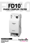
FD10™
7