1
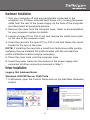
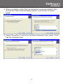
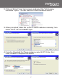
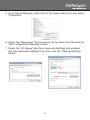
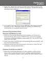
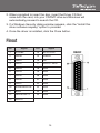
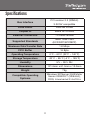
PCI1PM
Instruction Manual
PCI Parallel Adapter
1-Port Remappable PCI Parallel
Adapter Card
Manual Revision:01/10/2011
For the most up-to-date information, please visit www.startech.com
FCC Compliance Statement
This equipment has been tested and found to comply with the limits for a Class B digital
device, pursuant to part 15 of the FCC Rules. These limits are designed to provide
reasonable protection against harmful interference in a residential installation. This
equipment generates, uses and can radiate radio frequency energy and, if not installed
and used in accordance with the instructions, may cause harmful interference to radio
communications. However, there is no guarantee that interference will not occur in a
particular installation. If this equipment does cause harmful interference to radio or
television reception, which can be determined by turning the equipment off and on, the
user is encouraged to try to correct the interference by one or more of the following
measures:
• Reorient or relocate the receiving antenna.
• Increase the separation between the equipment and receiver.
• Connect the equipment into an outlet on a circuit different from that to which the receiver
is connected.
• Consult the dealer or an experienced radio/TV technician for help.
Use of Trademarks, Registered Trademarks, and other Protected Names and Symbols
This manual may make reference to trademarks, registered trademarks, and other
protected names and/or symbols of third-party companies not related in any way to
StarTech.com. Where they occur these references are for illustrative purposes only
and do not represent an endorsement of a product or service by StarTech.com, or an
endorsement of the product(s) to which this manual applies by the third-party company
in question. Regardless of any direct acknowledgement elsewhere in the body of
this document, StarTech.com hereby acknowledges that all trademarks, registered
trademarks, service marks, and other protected names and/or symbols contained in this
manual and related documents are the property of their respective holders.
Table of Contents
Introduction...................................................................... 1
Packaging Contents..................................................................... 1
System Requirements.................................................................. 1
Installation........................................................................ 2
DIP Switch Settings...................................................................... 2
Hardware Installation.................................................................... 3
Driver Installation.......................................................................... 3
Legacy ISA Address Mode....................................................... 3
Standard Plug-and-Play Mode................................................. 9
Pinout............................................................................... 10
Specifications................................................................... 11
Technical Support............................................................ 12
Warranty Information....................................................... 12
i
Introduction
The PCI1PM Re-mappable 1 Port PCI Parallel Card adds one fully
featured I/O mapped IEEE 1284 parallel port to your system using a
PCI expansion slot.
Saving time and money in costly upgrades of legacy hardware, the
re-mappable parallel card can be installed and configured using legacy
memory ranges (278, 378, and 3BC legacy ISA addresses) under
DOS® and Windows® operating systems for compatibility with legacy
devices such as security dongles that require a specific memory I/O
range for operation.
The card also supports standard installations, with plug-and-play
WHQL certified drivers for Windows® as well as support for DOS® and
Linux®.
Packaging Contents
• 1 x PCI Parallel card
• 1 x Low Profile Installation Bracket
• 1 x Driver CD
• 1 x Instruction Manual
System Requirements
• PCI enabled computer with available full or low profile PCI slot
• Microsoft® Windows® XP/Server 2003/Vista/Server 2008 R2/7
(32/64-bit), or DOS, or Linux® kernel 2.4.x/2.6.x
1
Installation
WARNING! PCI cards, like all computer equipment, can be severely
damaged by static electricity. Be sure that you are properly grounded
before opening your computer case or touching your PCI card.
StarTech.com recommends that you wear an anti-static strap when
installing any computer component. If an anti-static strap is unavailable,
discharge yourself of any static electricity build-up by touching a large
grounded metal surface (such as the computer case) for several
seconds. Also be careful to handle the PCI card by its edges and not
the gold connectors.
DIP Switch Settings
This card supports both standard PCI Plug-and-Play mode, as well as
the legacy ISA addresses 278, 378 and 3BC. Set the switches on the
card to the desired mode, prior to installation.
System Assigned
(PnP)
1 - OFF
2 - OFF
3 - OFF
4 - OFF
378 (Legacy ISA)
1 - ON
2 - ON
3 - OFF
4 - OFF
278 (Legacy ISA)
1 - ON
2 - OFF
3 - ON
4 - OFF
3BC (Legacy ISA)
1 - ON
2 - OFF
3 - OFF
4 - ON
2
Hardware Installation
1.Turn your computer off and any peripherals connected to the
computer (i.e. Printers, external hard drives, etc.). Unplug the power
cable from the rear of the power supply on the back of the computer
and disconnect all peripheral devices.
2.Remove the cover from the computer case. Refer to documentation
for your computer system for details.
3.Locate an open PCI or PCI-X slot and remove the metal cover plate
on the rear of the computer case.
4.Insert the card into the open PCI or PCI-X slot and fasten the card’s
bracket to the rear of the case.
NOTE: If installing the card into a small form factor/low profile system,
replacing the pre-installed full profile bracket with the included low
profile installation bracket may be necessary.
5.Place the cover back onto the computer case.
6.Insert the power cable into the socket on the power supply and
reconnect all other connectors removed in Step 1.
Driver Installation
Legacy ISA Address Mode
Windows 2000/XP/Server 2003/Vista
1.In Windows, open the Control Panel and run the Add New Hardware
wizard.
3
2.When prompted, select that the hardware is already installed, then
choose the “Add a new hardware device” from the list of device
types.
3.Select the option to install the hardware manually, then select “Ports”
has the hardware type.
4
4.From the Standard Port Types, select ECP Printer Port, then
proceed to complete the installation.
5.Once the hardware wizard has completed, access the Device
Manager by right-clicking on My Computer and selecting the
“Manage” option. In the Computer Management window, select
Device Manager from the left window panel.
6.Locate the new port under the “Ports” category and right-click on it
and select “Properties”.
7.In the Properties window, select the “Resources” tab along the top
and click the “Set Configuration Manually” button.
5
8.Select “I/O Range” under the Resource Settings then click the
“Change Settings” button.
9.Select the “Value” that matches the DIP switch settings used for the
adapter card and note any conflicts that appear. Accept the settings
and reboot the computer.
10.If a conflict is not reported in Device Manager, then the port should
be ready for use. Otherwise contact the system or motherboard
manufacturer for a possible work around.
Windows 7/Server 2008 R2
1.Access the Device Manager by right-clicking on My Computer
and selecting the “Manage” option. In the Computer Management
window, select Device Manager from the left window panel.
6
2.Click on “Action” from the top menu and select the “Add Legacy
Hardware” option. This will launch the Add Hardware wizard.
3.When prompted, select the option to install hardware manually, then
select “Ports” as the hardware type.
4.From the Standard Port Types category, select ECP Printer Port,
then proceed to complete the wizard.
7
5.From Device Manager, right-click on the newly added port and select
“Properties”.
6.Select the “Resources” tab from along the top tabs and then click the
“Set Configuration Manually” button.
7.Select the “I/O Range” field from Resource Settings and uncheck
the “Use Automatic Settings” box, then click the “Change Settings”
button.
8
8.Select the “Value” that matches the DIP switch settings used for the
adapter card and note any conflicts that appear. Accept the settings
and reboot the computer.
9.If a conflict is not reported in Device Manager, then the port should
be ready for use. Otherwise contact the system or motherboard
manufacturer for a possible work around.
Standard Plug-and-Play Mode
Windows 2000/XP/Server 2003
1.When the Found New Hardware wizard appears on the screen,
insert the Driver CD into your CD/DVD drive. If you are prompted
to connect to Windows Update, please select the “No, not this time”
option and click Next.
2.Select the option “Install Drivers Automatically (Recommended)” and
then click the Next button.
3.Windows should now start searching for the drivers. Once this has
completed, click the Finish button.
Windows Vista/7/Server 2008 R2
1.When the Found New Hardware window appears on the screen,
click on the “Locate and install drivers software (recommended)”
option. If prompted to search online, select the “Don’t search online”
option.
9
2.When prompted to insert the disc, insert the Driver CD that
came with the card, into your CD/DVD drive and Windows will
automatically proceed to search the CD.
3.If a Windows Security dialog window appears, click the “Install this
driver software anyway” option to proceed.
4.Once the driver is installed, click the Close button.
Pinout
Pin
Pin
Signal
1
STROBE
Signal
14
AUTO FEED
2
DATA0
15
ERROR
3
DATA1
16
INT
4
DATA2
17
SELECT INPUT
5
DATA3
18
GND
6
DATA4
19
GND
7
DATA5
20
GND
8
DATA6
21
GND
9
DATA7
22
GND
10
ACKNOWLEDGE
23
GND
11
BUSY
24
GND
12
PAPER EMPTY
25
GND
13
SELECT
10
Specifications
PCI revision 2.3 (33MHz)
Bus Interface
3.3V/5V compatible
Form Factor
Full/Low Profile
Chipset ID
Sunix UL7512EQ
External Connectors
1 x DB25 female
Supported Standards
IEEE 1284-1994
(ECP/EPP/SPP/BPP)
Maximum Data Transfer Rate
1.8 Mbps
FIFO Buffer
16 Byte
Operating Temperature
0°C ~ 60°C (32°F ~ 140°F)
Storage Temperature
-20°C ~ 85°C (-4°F ~ 185°F)
Humidity
5% ~ 95% RH
Dimensions
121.0mm x 61.0mm x 13.0mm
Weight
75g
Compatible Operating
Systems
Windows XP/Server 2003/Vista/
Server 2008 R2/7 (32/64-bit),
DOS, Linux kernel 2.4.x/2.6.x
11
Technical Support
StarTech.com’s lifetime technical support is an integral part of our
commitment to provide industry-leading solutions. If you ever need
help with your product, visit www.startech.com/support and access our
comprehensive selection of online tools, documentation, and downloads.
Warranty Information
This product is backed by a lifetime warranty.
In addition, StarTech.com warrants its products against defects in
materials and workmanship for the periods noted, following the initial
date of purchase. During this period, the products may be returned
for repair, or replacement with equivalent products at our discretion.
The warranty covers parts and labor costs only. StarTech.com does
not warrant its products from defects or damages arising from misuse,
abuse, alteration, or normal wear and tear.
Limitation of Liability
In no event shall the liability of StarTech.com Ltd. and StarTech.com USA
LLP (or their officers, directors, employees or agents) for any damages
(whether direct or indirect, special, punitive, incidental, consequential, or
otherwise), loss of profits, loss of business, or any pecuniary loss, arising
out of or related to the use of the product exceed the actual price paid
for the product. Some states do not allow the exclusion or limitation of
incidental or consequential damages. If such laws apply, the limitations
or exclusions contained in this statement may not apply to you.
12
StarTech.com has been making “hard-to-find easy” since 1985,
providing high quality solutions to a diverse IT and A/V customer
base that spans many channels, including government, education
and industrial facilities to name just a few. We offer an unmatched
selection of computer parts, cables, A/V products, KVM and Server
Management solutions, serving a worldwide market through our
locations in the United States, Canada, the United Kingdom and
Taiwan.
Visit www.startech.com today for complete information about all
our products and to access exclusive interactive tools such as the
Cable Finder, Parts Finder and the KVM Reference Guide.