1
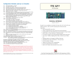
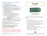
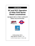
4
Combined Decoder SL51-2
108
109
110
111
112
113
116
121
122
123
124
125
126
127
128
129
130
131
132
133
134
135
136
137
138
139
140
141
142
143
144
Bitmask for endless manual sound:
ONLY operational when CV49 Bit 5 is set. For use with LGB pulse chains
Bit 0 for sound 1, Bit 1 for sound 2, Bit 3 for sound 3 aso…… Bit 6 for sound 7
Selection of CV Sets: Bit 0 = 0 ? CV-Set 1, Bit 0 = 1 ? CV-Set 2 for various use. Hard Reset
will only effect the selected CV-set, CV109 will be unchanged by Hard Reset
Load dependent sound variation: CV110 = 0 ? no load dependent sound variation
CV110 = 1 ? high dependency, CV110 = 15 low dependency to loadchanges
Intensiy of acknowledgment pulse (ACK): improves the programming capability, 128 = ca. 50%
of max. acknowledgment puls (Motor dependent) 150 = normal
RAND_1: Selection of aux. sound in idling (see CV131) CV112 = 0 ? auxillary sound off
Bit 0 - 7 ? Selection of auxillary sound
RAND_2: Selection of aux. sound in running condition (see CV131) CV113 = 0 ? auxillary sound
off
Bit 0 - 7 ? Selection of auxillary sound
Shunting function (yard mode): F3 default (CV37) remappable see CV35-42
Bit 0 = 1 ? CV3 and CV4 is disabled
Bit 1 = 1 ? max. speed will be half going forward and reverse
Bit 2 = 1 ? reverse only 65% max. speed (independent of shunting mode)
Register 0: Sound level main sound (running sound) 1 = low, 2 = medium, 3 = high, F1, CV121=0
? off
Register 1: Bit 0 - 1 aux.function 1 : Bit 2- 7 for number of repetitions, F2, CV122=0 ? off
Register 2: Bit 0 - 1 aux.function 2 : Bit 2- 7 for number of repetitions, F3, CV123=0 ?off
Register 3: Bit 0 - 1 aux.function 3 : Bit 2- 7 for number of repetitions, F4, CV124=0 ? off
Register 4: Bit 0 - 1 aux.function 4 : Bit 2- 7 for number of repetitions, F5, CV125=0 ? off
Register 5: Bit 0 - 1 aux.function 5 : Bit 2- 7 for number of repetitions, F6, CV126=0 ? off
Register 6: Bit 0 - 1 aux.function 6 : Bit 2- 7 for number of repetitions, F7, CV127=0 ? off
Register 7: Bit 0 - 1 aux.function 7 : Bit 2- 7 for number of repetitions, F8, CV128=0 ? off
Strong time: Time, when the sound after accelaration si being strongly reduced (unit: 0,5
seconds, valid for sounds in position 00-03 in the filelist)
Weak time: Time, when the sound after breaking is being slightly reduced (unit: 0,5 seconds,
valid for sounds in position 08-11 in the filelist)
Rand time: Minimum time between two aux.sounds (unit: 0,5 seconds! )
Stroke Base H: Time between two steam strokes at speed step full speed.
Stroke Base L: Time between two steam strokes for logical speed step 1 in seconds. 153 = 9,6
sec.
Constant K = 1476 / time
1. Exampel: 20 seconds wanted K = 1476 / 20 = 73,8 rounded 74; ? CV133 = 74, CV134 = 0.
2. Exampel: 3 seconds: K = 1476 / 3 = 492. for K>256 splitting into high and lowbyte is
necessary
CV134 = K / 256 (not rounded, decimals is simply cut off) 492 / 256 = 1,927875 ? CV134 = 1
CV133 = K - (CV134 * 256) = 492 - (256 * 1) = 236
Time between steam strokes: the time between 2 steam strokes at logical speed step 1 in
seconds (see CV133) Highbyte is set in CV 134.
Frequency_min: Sound pitch in lower range () 64 = default pitch
Frequency_max: Sound pitch in higher range () 64 = default pitch
Special CV: CV137 valid for F0 – F12, between. CV33 – CV46 remappable.
Bit0 – Function selection 0 = 8 Functions, 1 = 14 Functions (MAN Bit)
Bit1 = Zimo – Train numberimpuls: 0 = off, 1 = on
Bit2 = 1: strong/normal/weak switched with F1, only if CV110 is active, dimmable over CV54
Bit3 = 1: strong/normal/weak switched with F2, only if CV110 is active, dimmable over CV54
Bit4 = 1: Zimo speed control (HLU, MX9) 0 = off, 1 = on
Break time (HLU): Break delay for HLU section (For Zimo systems only)
Shortcircuit-threshold 1: direct cut-off at overload of functional outputs
Shortcircuit -threshold 2: fast cut-off at overload of functional outputs
Shortcircuit -threshold 3: slow cut-off at overload of functional outputs
Shortcircuit-threshold 1: direct cut-off at overload of motor output
Shortcircuit -threshold 2: fast cut-off at overload of motor output
Shortcircuit -threshold 3: slow cut-off at overload of motor output
0
0
0 - 255
0-1
4
1 - 15
255
0 - 255
255
0 - 255
255
0 - 255
0
0 - 255
User manual
Combi-decoder SL51-2
3
1-3
96
96
96
96
96
96
96
1
1
1
1
1
1
1
- 255
- 255
- 255
- 255
- 255
- 255
- 255
4
0 - 255
4
20
100
0 - 255
0 - 255
0 - 255
153
0 - 255
0
0 - 255
64
128
0 - 255
0 - 255
0
0 - 255
3
10
8
6
60
50
40
0
0
0
0
0
0
0
- 255
- 255
- 255
- 255
- 255
- 255
- 255
Table 2 CV Table
for N and H0-scale
Size 27/15/,.8mm (L/B/H)
Picture 1 the Decoder
Safety disclaimer
Not suitable for children under three years of age because of the danger of their swallowing the small constituent pieces. Improper use
can result injury from functionally necessary points an edges. For use only in dry areas. We reserve the right to make changes in line with
technical progress, product maintenance or changes in production methods. We accept no responsibility for error that may occur of
similar reason. We accept no responsibility for direct or indirect damage resulting from improper use, non-observance of instructions,
use of transformers or other electrical equipment that is not authorised for use with model railways or transformers and other electrical
equipment that has been altered, adapted or are faulty. Nor can we accept we accept responsibility for damage that results from
unsupervised adjustments to equipment or from acts of violence or from overheating or from effects of moisture etc. Furthermore in all
such cases the guarantee becomes invalid
The SL51-2 is delivered mounted in tubing. Fi t the decoder using double-sided adhesive tape, there should be no contact between
metal parts such as locomotive chassis or locomotive housing and the electronic of the decoder. Insulate all metalparts with
insulation tape so that shortcircuit can be avoided. Never cover the decoder with insulation tape, that will reduce the aircirculation around
the decoder wich could harm the decoder. Never touch the decoder when it is under power, this may damage both the software and
hardware of the decoder.
Grillparzergasse 5
A-2700 Wiener Neustadt
Tel. Fax : +43 2622 82086
Tel.: +43 664 4719963
http://www.tran.at e-mail: [email protected]
CT-Elektronik, www.tran.at
2
1.
Combined Decoder SL51-2
Technical data and installation
Combined decoder SL51-2
2.
Track voltage DCC............................................................................................................ 10-24V
Maxim um continuos current to motor....................................................................................... 1.5A
Maxim um peak current to motor 5sec ......................................................................................... 2A
Maximum continuos current aux. f unctions .......................................................................each 0.5A
Maxim um total current all aux. f unctions.................................................................................. 1.5A
High frequency motor control............................................................................................... 16kHz
Low frequency motor control........................................................................................ 30 – 150 Hz
Dimming frequency ..............................................................................................................80Hz
Maxim um continuos output sound ................................................................................ 1W/32 Ohm
Maxim um sound memory capacity at 11kHz, 8 Bit (Mono) ......................................... 44-160 Seconds
Operating temperature................................................................................................. -10 to 90°C
Dimensions ............................................................................................ (L x B x H) 27/15/3,8 mm
Configuration table (CV’s)
CV
1
2
3
4
5
6
7
8
9
13
17+18
19
Table 1 Technical data
1.1.
Connection of the SL51-2
29
SL51-2 view from above
Reed 2
Reed 1
SL51-2
Ansicht von oben
30
Motor rechts (orange)
Schiene rechts (rot)
Motor links (grau)
Schiene links (schwarz)
Speak + (braun)
Plus + (blau)
Speak - (braun)
33 - 42
43 - 46
105
106
User-CV : free for remembering purchase date or similar user information
107
Break threshold: Trigging of break sequence, CV107 = 50 ? Break sequence will be triggered
between speedstep 25-24 CV107 = 0 ? Break sequence will be triggered between speedstep 1-0
50
51
52
Hard Reset: CV1 = 0 resets all CV´s depending on setting of CV109 to factory setting.
Connection: The connected loudspeaker must have an impedance of min. 32 Ohm, if the intended loudspeaker has a lower
impedance a resistor must connected in series with the loudspeaker giving a combined resistance of minimum 32? .
53
For use of a Reed contact for synchronized steam stroke the Reed contact 1 should be connected to the positive pole (blue).
54
The idle current consumption of the decoder is ca. 50mA this is due to the LF-amplifier. A heat release at idle load is therefore
harmless. In operation under load the cooling element may reach a temperature up to 90°C. At track voltages over 24V the decoder
must be mounted on a metal surface (for example locomotive chassis) so that heat can be transported away.
55
56
The SL51 behaves in the service mode like a commercial locomotive decoder. The acknowledgement of programming is received via the
built in motor, a low impedance loudspeaker can therefore be installed without problem and does not have to be removed during
programming.
57
Notes for Roco Lokmaus users
59
60
61
64
58
The Roco Lokmaus System only supports addresses from 0-99. Therefore programming of CV-values above 99 is not directly
possible. The SL51 offers a solution to this problem. By setting CV53 = 1 the following CV that is being programmed will get a 1 in
front of the figures entered, setting CV53 = 2 means that the following entry will get a value starting at 200. For setting of values from
0-99, CV 53 must be set at 0.
Users of Digital systems that support the full range of values can off cause program the values directly without use of CV53. This
function can be used for all CV´s except for the Decoder address since programming of higher addresses than 99 would make the
locomotive unreachable for lokmaus users.
67-94
1
Explaination
Locomotive address: For short addresses when CV29 Bit 5 is set at 0
Starting voltage: Voltage to motor at Speed step 1
Acceleration: rate of acceleration
Deceleration: rate of deceleration
Maximum speed
Middle speed: together with CV2 and CV5 a three-point speed curve can be set. CV6 = 0 -->
linear speedcurve .
Versionsnummer:
Manufacturer ID
PWM: 13 – 63 stepless from 30 – 150 Hz,
141 – 191 ?16 kHz, for coreless and bell anchor motors
Analogue mode: Bit 0-3 switches output 1-4 on when operating on DC.
Extended addresses: is active when in CV 29 Bit 5 is set. (for example. CV29 = 42 when
address over 127 is wanted.)
Multi unit (consist) address
Configuration bits: decoder properties.
Bit value-calculation for CV
Bit 0 - Direction: 0 = normal 1 = inverted
29
Bit 1 - Speedsteps: 0 = 14/27, 1 = 28/128
Bit 0: 0 or 1
Bit 2 – Operating mode: 0 = only digital mode
Bit 1: 0 or 2
1 = conventional and digital
Bit 2: 0 or 4
Bit 3: not used
Bit 3: 0 or 8
Bit 4 – Speed curve :
Bit 4: 0 or 16
0 = Default-speed curve using CV 2, 5, 6
Bit 5: 0 or 32
1 = Free speed curve using CV 67 – 94
Bit 6: 0 or 64
Bit 5 – Address selection:
Bit 7: 0 or 128
0 = 1-127 according to CV 1
1 = 128 - 10240 according CV 17 + 18
Bit 6 not used
Bit 7 not used
Error diagnosis: 1 = Motor, 2 = Light, 3 = both short-circuit
Function mapping: according to NMRA for F0 - F7, CV33-42 = 0 ? Function off (1, 2, 4, 8, 16, 4,
8, 16, 32, 64)
Function mapping: according to NMRA for F8 - F11 CV43-46 = 0 ? Function off 16, 32, 64, 128
Configuration bits 1 for Sounds: Setting, influence of sound type, cylinder number aso. . . .
CV49 = 0 ? factory set for 4 cylinder steam engine
Bit 0 = 1 ? suitable for Reed contacts for wheel synchronising for steam engines dependent on
CV133 = number of Reed contacts -pulses per stroke . CV133 =1 ? 1 stroke /puls
Bit 1 = 2 ? diesel-, electric
Bit 2 = 4 ? 2 cylinder steam
Bit 3 = 8 ? 3 cylinder steam
Bit 4 = 16 ? no steam strokes during downhill run (only idle sound)
Bit 5 = 32 ? evaluate the LGB-puls from F1
Bit 6 = 64 ? no sound between stand still – running (whistle)
Bit 7 = 128 ? no sound between running – stand still (Breakes)
EMF intensity: how strong is EMF 0 = no influence, 255 = maximum. If you plan to use
locomotives in consist then reduce the value set in CV 50. This avoid models work against each
other if they can’t be configured to perform totally equal.
P-Value : optimizes EMF characteristic. Modify this variable to adapt to specific motor
requirements or characteristics.
I-Value : optimizes EMF characteristic. Modify this variable to adapt to specific motor
requirements or characteristics.
Special CV1: for Roco Lokmaus users
CV53 = 66 ? Programming and feedback off
CV53 = 77 ? Programming and feedback on
CV53 = 1 ? 100 + programmed value
CV53 = 2 ? 200 + programmed value
Special for users of Roco Lokmaus: to be able to use values over 99.
If CV53 = 1 or 2 all CV´s will get a 1 or a 2 in front of the programmed value.1 Users of command
stations with a complete value range do not use this feature.
PWM for function output: provides a dimming functionality CV54 = 50 means 50% of power
PWM for decoupler: represents the holding current for the decoupler, i.e. the reduced power for
holding after the uncoupling impulse.
Decoupler pulse time: how long is the impulse on the decoupler with full power until it is
reduced to the value defined CV 55. Time is set n 1/20 sec.
Dimming mask: turns dimming (defined in CV 54) on and off for each function output. Each bit
represents one function output
Dimming mask for decoupler function: defines which outputs should have that function enabled.
Each bit represents one function output.
Signal controlled speed: “L” only available in ZIMO environment.
Signal controlled speed: “U” only available in ZIMO environment.
Signal controlled acceleration reaction time: only available in ZIMO systems (unit: =1/20 sec)
Reference voltage : for EMF 160 = 16V track voltage
Free Speed curve: activated when Bit 4 in CV 29 is set to 1.
Default value: 9,18, 27, 36, 45, 54, 63, 72, 81, 90, 99,
108, 117, 126, 135,1 44, 153, 162, 171, 180, 189, 198, 207, 216, 225, 234, 243, 252
User-CV : free for remembering purchase date or similar user information
49
Notes on installation and Programming
3
3
3
4
4
0
0
Defaultvalue
1 - 127
0 - 255
0 - 255
0 - 255
0 - 255
0 - 255
-
0
0
variabel
117
13 - 63
141 - 191
0 - 255
12810240
1-127
2
0 - 255
148
0
0
0-3
---
0 - 255
---
0 - 255
0
0 - 255
255
0 - 255
80
0 - 255
40
0 - 255
0
0 - 255
50
32
0 - 100
0 - 100
60
0 - 255
0
0 - 255
0
0 - 255
168
84
1
160
0
0
0
0
- 255
- 255
- 255
- 255
---
0 - 252
0
0 - 255
0
0
0 - 255
0 - 255
Exampel: CV 50 shoud have the value 167: First you set CV53=1 then you set CV50=67. Through CV53=1 the value 167 will be written
to CV50.