1
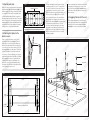
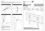
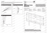
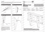
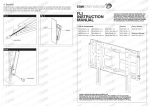
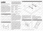
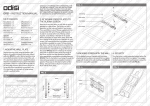
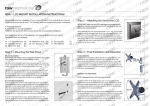
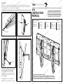
l
t
l
i
n
n
a
t
e
i
o
n
n
a
t
i
i
o
n
n
i
t
w
i
o
n
t
i
w
in atio
a
a
t
w
a
a
w
r
n
a
a
w
l
r
n
r
a
l
r
r
n
a
a
l
r
e
rawinternational
r
n
a
e
t
l
r
r
n
n
a
t
e
l
i
n
n
a
t
e
i
o
n
n
a
t
i
i
o
n
n
i
t
w
i
n
t
io
w
in atio
a
a
t
w
a
a
w
r
n
a
a
w
l
r
n
r
a
l
r
PT1 ter
n
a
a
l
r
e
r
n
a
t
l
r
r
n
n
a
e
l
i
n
n
a
t
e
i
o
n
n
INSTRUCTION
a
t
i
i
o
n
n
i
t
w
i
o
n
n
t
i
w rna
i
o
a
t
w
i
a
a
t
w
MANUAL
r
a
a
w
l
r
n
a
a
l
r
r
n
a
a
l
r
e
r
n
a
e
t
l
r
r
n
n
a
t
e
l
i
n
n
a
t
e
i
o
n
n
a
t
i
i
o
n
n
i
t
w
i
o
n
n
t
i
w
i
o
a
a
t
w
i
a
a
t
w
r
n
a
a
w rna
l
r
n
r
a
l
r
r
n
a
a
l
r
e
r
a
e
t
l
r
n
n
a
t
e
l
i
n
n
a
t
e
i
o
n
n
a
t
i
i
o
n
n
i
t
w
i
o
n
n
t
i
w
i
o
a
a
t
w
i
a
a
t
w
r
n
a
a
w rna
l
r
n
r
a
l
r
r
n
a
a
l
r
e
r
a
e
t
l
r
n
n
a
t
e
l
i
n
n
a
t
e
i
o
n
n
a
t
i
i
o
n
n
i
t
w
i
o
n
t
i
w
in atio
a
a
t
w
a
a
w
r
n
a
a
w
l
r
n
r
a
l
r
r
n
a
a
l
r
e
r
n
a
e
t
l
r
r
n
n
a
t
e
l
i
n
n
a
t
e
i
o
n
n
a
t
i
i
o
n
n
i
t
w
i
n
t
io
w
in atio
a
a
t
w
a
a
w
r
n
a
a
w
l
r
n
r
a
l
r
r
n
a
a
l
r
e
r
n
a
e
t
l
r
r
n
n
a
t
e
l
i
n
n
a
t
e
i
o
n
n
a
t
i
i
o
n
n
i
t
w
i
o
n
n
t
i
w
i
o
a
a
t
w
i
a
a
t
w
r
n
a
a
w
l
r
n
r
a
a
l
r
r
n
a
a
l
r
e
r
n
a
e
t
l
r
r
n
n
a
t
e
l
i
n
n
a
t
e
i
o
n
n
a
t
i
i
o
n
n
i
t
w
i
o
n
n
t
i
w
i
o
a
a
t
w
i
a
a
t
w
r
n
a
a
w rna
l
r
n
r
a
l
r
r
n
a
a
l
r
e
r
a
e
t
l
r
n
n
a
t
e
l
i
n
n
a
t
e
i
o
n
n
a
t
i
i
o
n
n
i
t
w
i
o
n
n
t
i
w
i
o
a
a
t
w
i
a
a
t
w
r
n
a
a
w rna
l
r
n
r
a
l
r
r
n
a
a
l
r
e
r
a
e
t
l
r
n
n
a
t
e
l
i
n
n
a
t
e
i
o
n
n
a
t
i
i
o
n
n
i
t
w
i
o
n
t
i
w
in atio
a
a
t
w
a
a
w
r
n
a
a
w
l
r
n
r
a
l
r
r
n
a
a
l
r
e
r
n
a
e
t
l
r
r
n
n
a
t
e
l
i
n
n
a
t
e
i
o
n
n
a
t
i
i
o
n
n
i
t
w
i
n
t
io
w
in atio
a
a
t
w
a
a
w
r
n
a
a
w
l
r
n
r
a
l
r
r
n
a
a
l
r
e
r
n
a
e
t
l
r
r
n
n
a
t
e
l
i
n
n
a
t
e
i
o
n
n
a
t
i
i
o
n
n
i
t
w
i
n
t
io
w
in atio
a
a
t
w
a
a
w
r
n
a
a
w
l
r
n
r
a
l
r
r
n
a
l
r
e
r
n
a
e
t
l
r
n
a
t
e
l ra
in
n
n
a
t
e
i
o
n
n
4. Security
Once the screen is safely suspended, please tighten the bolts on the bottom right and left corner of the
bracket using a screwdriver (DO NOT OVER TIGHTEN). This engages the front plates to the wall mounting
plate to ensure the screen cannot be lifted from the wall (fig. 7).
Fig. 5
CONSULT AUTHORISED SERVICE PERSONNEL FOR
THE INSTALLATION OF THIS UNIT. INSTRUCTIONS
MUST BE FOLLOWED PRECISELY FOR SAFE AND
STABLE INSTALLATION. RAW INTERNATIONAL ARE
NOT LIABLE FOR ANY DAMAGE OR INJURY CAUSED
BY MISHANDLING OR IMPROPER INSTALLATION.
Fig. 6
List of components
screen
bracket
M4x20mm x 4
M5x20mm x 4
M6x20m x 4
M8x20mm x 4
17x8.3x5 x 4
M4X600mm x 4 M5x55mm x 4
M6x55 x 4
M8x55mm x 4
17x8.3x10 x 4
3mm hex key x 1 M5x75mm 4
5mm hex key x 1 M8x75mm x 4
17x8.3x20 x 4
4mm hex key x 1
6mm hex key x 1 17x8.3x30 x 4
17x8.3x40 x 4
screw driver
Fig. 7
Fig. 8
allen key
screw driver
5. Adjusting the tilt mechanism
Now that the screen is safely suspended on the
wall, using an allen key loosen the fixing on the tilt
mechanism (fig. 8).
Once you have chosen your desired tilt angle
tighten the fixing on the tilt mechanism once again.
Spacers
INSTALLATION (PLEASE READ CAREFULLY)
INSTALLATION OF THIS UNIT SHOULD ONLY BE CARRIED OUT BY QUALIFIED
TECHNICIANS. INSTALL IN AN APPROPRIATE LOCATION ONLY AFTER CHECKING
WALL STRUCTURE AND DURABILITY FOR ACCIDENT PREVENTION. CONSULT A
QUALIFIED BUILDER IF IN ANY DOUBT AS TO STRUCTURAL INTEGRITY OF WALL.
l
t
l
i
n
n
a
t
e
i
o
n
n
a
t
i
i
o
n
n
i
t
w
i
o
n
t
i
w
in atio
a
a
t
w
a
a
w
r
n
a
a
w
l
r
n
r
a
l
r
r
n
a
a
l
r
e
r
n
a
e
t
l
r
r
n
n
a
t
e
l
i
n
n
a
t
e
i
o
n
n
a
t
i
i
o
n
n
i
t
w
i
n
t
io
w
in atio
a
a
t
w
a
a
w
r
n
a
a
w
l
r
n
r
a
l
r
r
n
a
a
l
r
e
r
n
a
e
t
l
r
r
n
n
a
t
e
l
i
n
n
a
t
e
i
o
n
n
a
t
i
i
o
n
n
i
t
w
i
o
n
n
t
i
w rna
i
o
a
t
w
i
a
a
t
w
r
a
a
w
l
r
n
a
a
l
r
r
n
a
a
l
r
e
r
n
a
e
t
l
r
r
n
n
a
t
e
l
i
n
n
a
t
e
i
o
n
n
a
t
i
i
o
n
n
i
t
w
i
o
n
n
t
i
w
i
o
a
a
t
w
i
a
a
t
w
r
n
a
a
w rna
l
r
n
r
a
l
r
r
n
a
a
l
r
e
r
a
e
t
l
r
n
n
a
t
e
l
i
n
n
a
t
e
i
o
n
n
a
t
i
i
o
n
n
i
t
w
i
o
n
n
t
i
w
i
o
a
a
t
w
i
a
a
t
w
r
n
a
a
w rna
l
r
n
r
a
l
r
r
n
a
a
l
r
e
r
a
e
t
l
r
n
n
a
t
e
l
i
n
n
a
t
e
i
o
n
n
a
t
i
i
o
n
n
i
t
w
i
o
n
t
i
w
in atio
a
a
t
w
a
a
w
r
n
a
a
w
l
r
n
r
a
l
r
r
n
a
a
l
r
e
r
n
a
e
t
l
r
r
n
n
a
t
e
l
i
n
n
a
t
e
i
o
n
n
a
t
i
i
o
n
n
i
t
w
i
n
t
io
w
in atio
a
a
t
w
a
a
w
r
n
a
a
w
l
r
n
r
a
l
r
r
n
a
a
l
r
e
r
n
a
e
t
l
r
r
n
n
a
t
e
l
i
n
n
a
t
e
i
o
n
n
a
t
i
i
o
n
n
i
t
w
i
o
n
n
t
i
w
i
o
a
a
t
w
i
a
a
t
w
r
n
a
a
w
l
r
n
r
a
a
l
r
r
n
a
a
l
r
e
r
n
a
e
t
l
r
r
n
n
a
t
e
l
i
n
n
a
t
e
i
o
n
n
a
t
i
i
o
n
n
i
t
w
i
o
n
n
t
i
w
i
o
a
a
t
w
i
a
a
t
w
r
n
a
a
w rna
l
r
n
r
a
l
r
r
n
a
a
l
r
e
r
a
e
t
l
r
n
n
a
t
e
l
i
n
n
a
t
e
i
o
n
n
a
t
i
i
o
n
n
i
t
w
i
o
n
n
t
i
w
i
o
a
a
t
w
i
a
a
t
w
r
n
a
a
w rna
l
r
n
r
a
l
r
r
n
a
a
l
r
e
r
a
e
t
l
r
n
n
a
t
e
l
i
n
n
a
t
e
i
o
n
n
a
t
i
i
o
n
n
i
t
w
i
o
n
t
i
w
in atio
a
a
t
w
a
a
w
r
n
a
a
w
l
r
n
r
a
l
r
r
n
a
a
l
r
e
r
n
a
e
t
l
r
r
n
n
a
t
e
l
i
n
n
a
t
e
i
o
n
n
a
t
i
i
o
n
n
i
t
w
i
n
t
io
w
in atio
a
a
t
w
a
a
w
r
n
a
a
w
l
r
n
r
a
l
r
r
n
a
a
l
r
e
r
n
a
e
t
l
r
r
n
n
a
t
e
l
i
n
n
a
t
e
i
o
n
n
a
t
i
i
o
n
n
i
t
w
i
n
t
io
w
in atio
a
a
t
w
a
a
w
r
n
a
a
w
l
r
n
r
a
l
r
r
n
a
l
r
e
r
n
a
e
t
l
r
n
a
t
e
l ra
in
n
n
a
t
e
i
o
n
n
1. Mounting wall plate
Fig. 1
Remove security screw from bottom of bracket and
detach front plate (fig. 3). Mount wall plate (fig. 1) on
wall in desired position using screws/ bolts suitable
to construction of the wall. (If in any doubt please
consult a qualified builder). Attach screws/bolts
through as many holes/slots as possible. There are a
total of 22 fixing holes on the back plate, however the
minimum amount of fixings that Raw International
recommend is six. (If in any doubt as to strength
of fixings please consult a qualified builder.)
Mounting holes/slots
Fig. 2
2. Attaching front plates to the
plasma screen
Firstly loosen the fixing which controls the tilt
mechanism on the front plate (fig. 2). This will
allow clear access to the front plate fixing holes
which will be used to attach the from plate to the
screen. Place the screen face down on soft cloth
(to prevent damage) on a flat surface. The fixings
you use is dependent on the make and model
of your screen. There are different sets of fixings
supplied with the bracket. Only ONE set of fixings
will be required. In order to ascertain which set
of fixings will be required, screw fixings in the
back of the screen before attempting to attach
front plates. Only ONE set of fixings will be of the
correct diameter for your screen.
It is important that the front plates are fixed as
centrally as possible to screen. To help achieve
this, there is a 2mm hole in the centre of each of
the front plates. Line this hole up so it is equal
distance between the top and bottom fixings on
the back of the screen (fig. 3). Once it is lined
up, the nearest fixing hole on the front plates to
the top fixing on the plasma screen are the ones
that should be fixed first (fig. 4) using appropriate
screws/washers/isolators/spacers. Then fix
the bottom two fixings through the slots using
appropriate screws/washers/isolators/spacers.
Please use an Allen key to tighten all four fixings.
Only use isolators if back of screen is not flush
with the front plates.
Ensure front plates are situated in a centralised
horizontal position, tighten the screws on the
top of the front plates (fig. 5 overleaf) using a
screw driver. Now fully tighten the fixing on the
tilt mechanism.
3. Engaging Plasma with the wall
Lift the display (minimum 2 people) with front
plates attached so that the bars engage with the
angled slots on the wall mounting plate (fig. 6
overleaf), the screen is now safely suspended.
Fig. 4
allen key
steel fixings
steel washer
front plates
Fig. 3
screen
nylon isolator
2mm
hole
equal distance to 2mm hole
screen
security
screw
fixings holes on back of screen