1
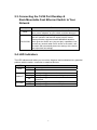
16/24 Port Desktop & Rack-mountable Fast Ethernet Switch User Manual Certification FCC Statement This equipment has been tested and found to comply with the limits for a Class B digital device, pursuant to part 15 of the FCC rules. These limits are designed to provide reasonable protection against harmful interference in a residential installation. This equipment generates, uses and can radiate radio frequency energy and, if not installed and used in accordance with the instructions, may cause harmful interference to radio communications. However, there is no guarantee that interference will not occur in a particular installation. If this equipment does cause harmful interference to radio or television reception, which can be determined by turning the equipment off and on, the user is encouraged to try to correct the interference by one or more of the following measures: - Reorient or relocate the receiving antenna. - Increase the separation between the equipment and receiver. - Connect the equipment into an outlet on a circuit different from that to which the receiver is connected. - Consult the dealer or an experienced radio/TV technician for help. To assure continued compliance, any changes or modifications not expressly approved by the party responsible for compliance could void the user’s authority to operate this equipment. (Example- use only shielded interface cables when connecting to computer or peripheral devices) FCC Radiation Exposure Statement This equipment complies with FCC RF radiation exposure limits set forth for an uncontrolled environment. This transmitter must not be co-located or operating in conjunction with any other antenna or transmitter. This equipment complies with Part 15 of the FCC Rules. Operation is subject to the following two conditions: (1) This device may not cause harmful interference, and (2) This device must accept any interference received, including interference that may cause undesired operation. Caution! The manufacturer is not responsible for any radio or TV interference caused by unauthorized modifications to this equipment. Such modifications could void the user authority to operate the equipment 2 Package Contents The following items should be found in your package: 16/24 Port Desktop or Rack-mountable Fast Ethernet Switch Power Adapter User Manual Rack Brackets Screws Make sure that the package contains above items. If any of the above items is missing or damaged, please contact the store you bought this product from. 3 Content 1. INTRODUCTION 5 1.1. PRODUCT OVERVIEW 5 1.2. MAIN FEATURES 5 1.3. STANDARDS 6 1.4. WORKING ENVIRONMENT 6 2. INSTALLATION 7 2.1. BEFORE INSTALLATION 7 2.2. INSTALLATION 7 2.3. CONNECTING THE 16/24 PORT DESKTOP & RACK-MOUNTABLE FAST ETHERNET SWITCH TO YOUR NETWORK 8 2.4. LED INDICATORS 8 3. TROUBLESHOOTING 9 4 1. Introduction 1.1. Product Overview The 16/24 Port Desktop & Rack-mountable Fast Ethernet Switch is designed to allow simultaneous transmission of multiple packets via an internal high-speed data channel. This means that it can partition a network more efficiently than bridges or routers in most environments .This 16/24 Port Desktop & Rack-mountable Fast Ethernet Switch is a highly reliable network switch and is the ideal device for bridging Ethernet to Fast Ethernet work groups or networks .Simple and cost-effective, it supports IEEE802.3 10Base-T Ethernet and IEEE802.3u 100Base-TX Fast Ethernet. Designed specifically for connecting work group devices and desktops, companies no longer have to invest in expensive and inflexible switches engineered primarily for backbone implementations. Companies can deploy this scalable, affordable switch that increases the aggregate bandwidth of the network by boosting throughput to the work groups that need it most. 1.2. Main Features Compliant with IEEE802.3 10Base-T Ethernet, IEEE802.3u 100Base-TX 16/24 port 10/100Mbps TX Auto-Negotiation Ethernet Switch 3.2/4.8Gbps switching fabric capacity Full/Half-Duplex capability on each TX port Supports TP interface Auto MDIX function for auto TX/RX swap IEEE802.3x flow control for full-duplex, back pressure function for half-duplex operation Supports up to 8K MAC addresses LED indicators for simple diagnostics Built-in power supply Plug and Play 5 1.3. Standards IEEE 802.3 10Base-T IEEE 802.3u 100Base-TX IEEE 802.3x Flow Control IEEE 802.3az 1.4. Working Environment Temperature 0° to 40° C (operating) -40° to 70° C (storage) Humidity 10% to 90 % non-condensing (operating) 5% to 90% non-condensing (storage) Power 100 - 240VAC, 50 - 60Hz 6 2. Installation 2.1. Before Installation Take note of the following conditions before using your switch: Install the 16/24 port desktop & rack-mountable fast Ethernet switch in a fairly cool and dry place. See Working Environment for the acceptable operating temperature and humidity ranges Install the switch in a site free from strong electromagnetic sources, vibration, dust, and direct sunlight. Leave at least 10cm of space to both the left and right of the switch for ventilation. Visually inspect the AC power jack and make sure the power adapter cord is securely connected. Do not place items on top of switch 2.2. Installation Desktop or Shelf Installation When installing the switch on a desk or shelf, the rubber feet included with the device should first be attached. Attach these cushioning feet on the bottom at each corner of the device. Allow enough ventilation space between the device and the objects around it. Rack Installation The Switch can be mounted in an standard 1U rack space. To install, attach the mounting brackets (one on each side) and secure them with the screws provided. Then, use the screws provided with the rack to mount the Switch in the rack. 7 2.3. Connecting the 16/24 Port Desktop & Rack-Mountable Fast Ethernet Switch to Your Network Description PWR 1X-16X/24X Function Connect to power adapter provided with unit. Don’t use other power adapters as your switch could be damaged. These ports support network speeds of 10Mbps or 100Mbps, and can operate in half and full-duplex transfer modes. These ports also support automatic MDI/MDIX detection, which gives the Switch true ‘plug and play’ capabilities. Just connect any network cable from a device to the switch, and the switch will automatically detect the settings of the device and adjust itself accordingly. 2.4. LED Indicators The LED Indicators will allow you to monitor, diagnose and troubleshoot any potential problem with the switch, connection or attached devices. LED PWR LINK/ACT Function On Off ON Flashing Off 10/100M ON OFF Power on Power off Corresponding port connection normal Corresponding port data transmitting Corresponding port connection abnormal/not connected Corresponding port works at 100Mbps Corresponding port works at 10Mbps 8 3. Troubleshooting 1. The Power LED is not lit Check if the AC power cord is well connected. Try to unplug and plug back in the power cord to the switch or try another power outlet. 2. The Link LED is not lit Make sure the network configuration of connecting device is correct, and network card and drivers are installed correctly. Check the cable connections. Make sure the cable distance between the switch and other IEEE802.3 compatible network device does not exceed 100 meters. 3. Performance is bad Check the status of Ethernet switching. If Ethernet switching is set to full-duplex on one device but a partner is set to half-duplex, then performance will be poor. Make sure the cable between the switch and other IEEE802.3 compatible network device is Category 5 UTP or better. 4. Some devices can’t talk to other devices on the network Check status of the Link LEDs to make sure devices are linked. Make sure that the devices' network configurations are correct. Reset the switch if needed. 9