1
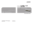
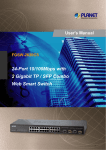
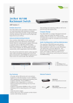
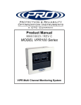
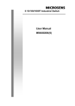
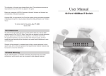
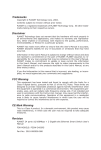
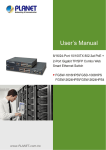
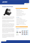
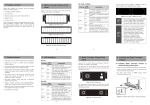
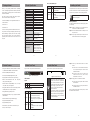
1. Package Content
3. Product Specification
Thank you for purchasing PLANET 24-Port 10/100Mbps
+2-Port unmanaged Gigabit Ethernet Switch, FGSW-2620.
Terms of “Switch” in following section of this User’s Manual
means the FGSW-2620.
Upon open the box of the Switch and carefully unpack it.
The box should contain the following items:
● 24-Port 10/100Mbps+ 2-Port Gigabit Ethernet Switch x 1
● User’s Manual x 1
● Power Cord x 1
● Rubber Feet x 4
● Two rack-mounting brackets with attachment screws x 6
If any of these are missing or damaged, please contact your
dealer immediately, if possible, retain the carton including
the original packing material, and use them against to
repack the product in case there is a need to return it to us
for repair.
Product
Hardware Specification
10/100Base-TX MDI/MDIX Ports
10/100/1000Base-T MDI/MDIX Ports
Throughput (packet per second)
Switch fabric
Weight
Power Consumption / Dissipation
Power Requirement
Dimensions (W x D x H)
Switch Processing Scheme
Address Table
Power Green Ethernet
Operating: 0~50 Degree C
Storage: -10~70 Degree C
Humidity Operating:
5% to 90%, Storage: 5% to 90%
(Non-condensing)
Green
IEEE
IEEE
IEEE
IEEE
IEEE
● Features Store-and-Forward
filtering and forwarding rates
mode
with
wire-speed
● Hardware based 10/100/1000Mbps, half / full duplex
mode, flow control, auto-negotiation
● Comply IEEE 802.3x flow control for full duplex operation
and Backpressure for half duplex operation
● Comply IEEE 802.1p Quality of Service
● Integrated address look-up engine, support 8K absolute
MAC addresses
● Automatic address learning and address aging
● Supports Auto MDI/MDI-X function
● Support CSMA/CD protocol
● 100~240V AC, 0.6A, 50~60Hz universal Power input
● FCC, CE class A compliant
-2-
not
need
Step 1: Attach the rubber feet to the recessed areas on
the bottom of the Fast Ethernet Switch.
Step 2: Place the Fast Ethernet Switch on desktop near an
AC power source.
Step 3: Keep enough ventilation space between the Fast
Ethernet Switch and the surrounding objects.
-5-
5. Switch Rear Panel
Figure 2 shows a rear panel of Fast Ethernet Switch.
Figure 2: FGSW-2620 rear panel
LED Indicators
System
Color
Function
PWR Green Lights to indicate that the Switch has power.
Per 10/100Mbps port
LED
does
To install the Fast Ethernet Switch on desktop, simply follow
the next steps:
Figure 1: FGSW-2620 front panel
LED
Note
This Fast Ethernet Switch
software configuration.
Desktop Installation
● 24-Port 10/100Mbps Fast Ethernet ports
● Supports powerful Green Ethernet to power saving
This part describes how to install your Fast Ethernet Switch
and make connections to it. Please read the following topics
and perform the procedures in the order being presented.
802.3 (Ethernet)
802.3u (Fast Ethernet)
802.3ab (Gigabit Ethernet)
802.3x (Full-duplex Flow Control)
802.1p (Class of Service)
Figure 1 shows a front panel of Fast Ethernet Switch.
● 2-Port 10/100/1000Mbps Gigabit Ethernet ports
6. Installing the Switch
FCC Part 15 Class A, CE
4. Switch Front Panel
● Comply with IEEE 802.3, 10Base-T, IEEE 802.3u 100BaseTX, IEEE 802.3ab 1000Base-T Ethernet standard
Lights to indicate the port is run at
10/100/1000Mbps.
Lights to indicate the port is run at
1000Mbps.
1000Mbps Green
Off: indicate that the port is operating
at 10/100Mbps.
-3-
2. Product Features
Function
24
2
6.54Mpps
8.8Gbps
2.40 kg
18.8 Watts / 64 BTU
100~240 VAC, 0.6A, 50-60 Hz
440 x 180 x 44mm, 1U height
Store-and-Forward
8K entries
From 10m to 100m Saving up to 12%
Temperature
-1-
Color
LNK/ACT
Back pressure for half duplex, IEEE
802.3x Pause Frame for full duplex
Standards Compliance
LED
FGSW-2620
Flow Control
Standards Conformance
Regulation Compliance
Per 10/100/1000Mbps port
Power
Notice
Color
Function
Lights to indicate the link through that
port is established successfully.
LNK/ACT Green Blinks indicate that the Switch is
actively sending or receiving data over
that port.
1. The device is a power-required device, it
means, it will not work till it is powered. If
your networks should active all the time,
please consider using UPS (Uninterrupted
Power Supply) for your device. It will
prevent you from network data loss or
network downtime.
2. In some area, installing a surge suppression
device may also help to protect your Fast
Ethernet Switch from being damaged by
unregulated surge or current to the Switch
or the power adapter.
-7-
Step 4: Connect your Fast Ethernet Switch to network
devices.
A. Connect one end of a standard network cable
to the 10/100 RJ-45 ports on the front of the
Fast Ethernet Switch.
B. Connect the other end of the cable to the
network devices such as printer servers,
workstations or routers…etc.
Step 5: Supply power to the Fast Ethernet Switch.
A. Connect one end of the power cable to the Fast
Ethernet Switch.
B. Connect the power plug of the power cable to a
standard wall outlet.
When the Fast Ethernet Switch receives power, the Power
LED should remain solid Green.
Lights to indicate the port is run at
100Mbps.
100Mbps Green
Off: indicate that the port is operating
at 10Mbps.
-4-
-6-
-8-
Rack Mounting
To install the Fast Ethernet Switch in a 19-inch standard
rack, follow the instructions described below.
Step 1: Place your Fast Ethernet Switch on a hard flat
surface, with the front panel positioned towards
your front side.
Step 2: Attach a rack-mount bracket to each side of the
Switch with supplied screws attached to the
package. Figure 3 shows how to attach brackets to
one side of the Fast Ethernet Switch.
Customer Support
Thank you for purchase PLANET products. You can browse
our online FAQ resource at the PLANET Web site first to
check if it could solve you issue. If you need more support
information, please contact PLANET switch support team.
PLANET online FAQ:
http://www.planet.com.tw/en/support/faq.php?type=1
Switch support team mail address:
[email protected]
Copyright @ PLANET Technology Corp. 2010.
Contents subject to revision without prior notice.
PLANET is a registered trademark of PLANET Technology
Corp. All other trademarks belong to their respective
owners.
Figure3: Attaching the brackets to the Fast Ethernet Switch
Caution
You must use the screws supplied with the
mounting brackets. Damage caused to the parts
by using incorrect screws would invalidate your
warranty.
-9-
- 11 -
Step 3: Secure the brackets tightly.
Energy Saving Note of the Device
Step 4: Follow the same steps to attach the second
bracket to the opposite side.
This power required device does not support Standby mode
operation.
Step 5: After the brackets are attached to the Fast
Ethernet Switch, use suitable screws to securely
attach the brackets to the rack, as shown in Figure
4.
For energy saving, please remove the power cable to
disconnect the device from the power circuit.
Without removing power cable, the device will still
consuming power from the power source. In the view of
Saving the Energy and reduce the unnecessary power
consuming, it is strongly suggested to remove the power
connection for the device if this device is not intended to be
active.
Figure 4: Mounting the Fast Ethernet Switch in a Rack
Step 6: Proceeds with the steps 4 and steps 5 of Desktop
Installation to connect the network cabling and
supply power to your Fast Ethernet Switch.
- 10 -
- 12 -
- 13 -
- 14 -