1
OMNI
TM
Combined Bar Code
and
Magnetic Stripe Reader
Keyboard Wedge
and
USB/Keyboard Wedge
User’s Manual
Agency Approved
Specifications for subpart B of part 15 of FCC rule for a Class A computing device.
Limited Warranty
ID TECH warrants this product to be in good working order for a
period of one year from the date of purchase. If this product is not in
good working order as warranted above, or should this product fail
to be in good working order at any time during the warranty period,
repair or replacement shall be provided by ID TECH.
This warranty does not cover incidental or consequential damages
incurred by consumer misuse, or modification of said product. For
limited warranty service during the warranty period, please contact
ID TECH to obtain an RMA number and instructions for returning the
product.
©2005 International Technologies & Systems Corporation. The information contained herein is provided to the user as a convenience.
While every effort has been made to ensure accuracy, ID TECH is not
responsible for damages that might occur because of errors or omissions, including any loss of profit or other commercial damage. The
specifications described herein were current at the time of publication,
but are subject to change at any time without prior notice.
ID TECH is a registered trademark of International Technologies &
Systems Corporation. Omni and Value through Innovation are trademarks of International Technologies & Systems Corporation.
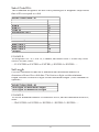
Table of Contents
Section 1. Introduction
Description
1
Section 2. Installation
Host Connection Step
2
Section 3. Operation
Operating Procedure
3
Section 4. Configuration
Configuration Setup Procedure
Default Settings
Terminal Type Selection
General Selections
Code ID Definitions
Bar Code Message Formatting Selections
Magnetic Stripe Formatting Selections
Bar Code Selections
Magnetic Stripe Selections
Reviewing Configuration Selections
4
4
6
6
7
10
11
13
15
28
29
Section 5. Data Editing
Data Fields
Data Editing Formulas
The Formula Sequence
Using the Data Editing Functions
Data Editing Commands
Omni Data Flow
Examples
31
32
33
34
35
36
41
42
Section 6. Troubleshooting
General Procedures
Keyboard Interface Problems
Scanning Configuration Problems
45
45
46
47
Appendix A. Bar Code Default Settings
48
Appendix B. Magnetic Stripe Data Output Format
51
Appendix C. Function Code Table
52
Appendix D. Magnetic Stripe Standard Data Formats
ISO Credit Card
California Driver’s License
AAMVA Driver’s License
53
54
56
Appendix E. Connector Pin Outs
Keyboard Ports
57
Apendix F. USB/Keyboard Interface
Installation
Operation
58
59
Section 1
INTRODUCTION
Description
The Omni™ slot reader can scan and decode most popular bar codes, as well
as read 1, 2, or 3 tracks of magnetic stripe information. In addition, it has full
data editing capabilities.
When connected to the host computer, the Omni is completely compatible
with the host’s software. The decoded data appears to the host as if it were
entered manually by the operator through the keyboard.
The keyboard wedge unit is fully programmable through the keyboard using
any document editor. The USB/Keyboard Wedge unit can be programmed
through the keyboard using the ID TECH USB Reader Setup Utility. (Please
see Apprendix F for details.) The data can be formatted with preamble/postamble and terminator characters to match the format expected by the host.
Power is obtained from the host.
The programming codes are the same for both keyboard wedge and USB/
Keyboard Wedge units. Please see Appendix F for details.
1
Section 2
INSTALLATION
Host Connections
The Omni reader is connected between the keyboard input port of the host
computer and the keyboard itself using a “Y” cable. The “Y” cable has a
6-pin mini-DIN female on one end, and a 6-pin mini-DIN male on the other
end.
To connect the reader to the host, turn the power off and disconnect the keyboard from the computer. Connect the keyboard to the female end of the “Y”
cable. Then insert the male end of the “Y” cable into the keyboard port. This
“wedges” the reader between the host and the keyboard.
Manually-entered data from the keyboard passes through the unit to the host,
leaving the keyboard fully functional at all times.
Data from either of the input heads is transmitted to the host keyboard port,
where it appears to the host as coming directly from the keyboard. This makes
the reader, as a data source, completely transparent to the host’s application
software. In other words, if it is expecting data from the keyboard, that same
data can be entered via the Omni and make no difference to the host.
Since the host computer’s application software is expecting data to be input in
a particular order and format, the reader’s output can be configured to simulate the keyboard-entered data stream by adding terminating characters and
special preamble and/or postamble character strings to scanned data.
2
Section 3
OPERATION
Operating Procedure
The Omni reader is easy to operate. Just follow these simple steps:
1. Make sure the reader is properly connected (see sections 2 and 6) and is receiving sufficient power. (See Section 6, Troubleshooting, if there is a cabling
or power problem.)
2. To read a card, slide the card, in either direction, through the reader slot,
with the bar code facing the optical head (LED side) or the magnetic stripe
facing the magnetic head (opposite side).
3. Once the entire bar code or magnetic stripe has been read, the LED
indicator will light up as green to signal a “good read.” If a good read is not
obtained, the LED indicator will light up as red.
4. A beep will also sound to indicate a good read on the bar code or each
magnetic track, as appropriate. If all three tracks have been read successfully,
the reader will beep three times.
5. The decoded data will be transmitted to the host application.
Note: Output data can be verified in Notepad (or another document editor).
3
Section 4
CONFIGURATION
The Omni reader must be appropriately configured to your application.
Configuration settings enable the reader to work with the host system. These
settings are programmed into the reader through the keyboard. Once programmed, these configuration settings are stored in the reader’s non-volatile
memory (so they are not affected by the cycling of power).
Bar Code Input
The reader may need to be configured to accept the desired bar code data and
format it for transmission to the host. This includes enabling it for the correct
bar code symblogy, setting any check digit, start/stop codes, preamble/postamble, and min/max symbol length. Default settings enable all least restrictive settings.
Magnetic Stripe Input
The reader may need to be configured to accept the desired magnetic stripe
data and format it for transmission to the host. The encoded data can be
ANSI, ISO, AAMVA, and California Drivers License magnetic stripe formats.
The reader can be configured to read any track, 1 only, 2 only, 3 only, 1 & 2, 2
& 3, or 1,2 &3. In addition, track start/stop sentinels can be sent or suppressed
and track 2 account number information only can be selected along with user
selectable track separator characters. Default settings enable reading on all
available tracks (depending on whether the reader is equipped to read one,
two, or three tracks).
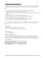
Configuration Setup Procedure
1. On an AT-compatible computer, enter any document editor. (Notepad is
recommend in the Windows environment.)
2. Turn on the CAPS LOCK feature on the keyboard, as the configuration
code is case sensitive.
3. Identify the settings that you wish to change. All options are covered in the
various setup groups explained in this manual. (The reader’s related setting
features are grouped together.)
4. Enter the GROUP SETUP MODE by typing /E/D/FX (where X is the
group name identified in Step 3).
4
5. Press the <Enter> key. The reader will beep twice to indicate the reader is
now in the Setup Mode for group X.
6. Type the two-character selection code for the feature that you wish to
change.
7. Press the <Enter> key. The reader will beep twice to indicate the code is
accepted by the reader as a valid code for Setup Group X.
8. Type the one-character code for the change you wish to make.
9. Press the <Enter> key. The reader will beep twice to indicate the code is
accepted by the reader as a valid code for that particular feature.
10. Repeat Steps 6 to 9 for any other features that you wish to change in the
same Setup Group.
11. Save the changes and exit Setup Mode by typing XZ. (Of course, X must
be the same group name entered in Step 4.)
12. Press the <Enter> key. The reader will sound four beeps to indicate
the new settings have been saved in the reader and the reader is back to the
normal reading mode.
EXAMPLE:
To set the reader’s beep volume to LOW, enter following setup code in
Notepad:
/E/D/FB<Enter>B1<Enter>1<Enter>BZ<Enter>
The setup routine is always the same, regardless of group:
1. Enter group setup mode.
2. Enter the feature selection code.
3. Change the setting for that feature.
4. Save the change and exit.
The reader’s response is always the same, regardless of group:
· Two slow beeps indicate the code has been accepted by the reader.
· Four slow beeps indicate the reader has saved the settings and has exited the
setup mode successfully.
· Four quick beeps indicate the code entered is invalid and has been rejected
by the reader.
Notes: Type codes in slowly (no more than two characters per second). If there
is a typing error, do not use the BACKSPACE key to correct it. Instead, press the
<ENTER> key. The reader will sound four quick beeps to indicate the error code has
been rejected. Then re-enter the code correctly.
For the numeric character in the code, use the number keys located on top of the main
alphanumeric keypad. Do not use the number keypad located on the right side of the
keyboard.
Before proceeding to enter the next code, make sure the reader gives the correct
number of beeps when <ENTER> is depressed.
5
Codes must be typed from an external keyboard when the reader is connected to a
Notebook PC. (The Omni’s USB keyboard interface model is the best choice for use
with a Notebook PC.)
If a code is typed correctly, but the reader won’t give the appropriate beeps, it may be
necessary to press the CAPS LOCK key a few times and leave the CAPS LOCK feature
on. Then try to re-enter the configuration code.
Default Settings
The Omni reader is shipped from the factory with the default settings already
programmed. In the following sections, the default settings are shown in
boldface. For a list of all default settings, please see Appendix A. In order to
modify these settings, the host computer and keyboard must be IBM PC/ATcompatible.
By default, the reader has been programmed with the least restricted settings,
thus making the Omni reader able to read most bar code labels and standard
format magnetic stripe cards out of box.
The reader’s output data format can be reconfigured to meet the expectations
of the host application.
To reset the reader to the factory default, follow these steps:
1. On an AT-compatible computer, enter any document editor. (Notepad is
recommend in the Windows environment.)
2. Turn on the CAPS LOCK feature on the keyboard, as the configuration
code is case sensitive.
3. Enter the GROUP SETUP MODE by typing /E/D/FA.
4. Press the <Enter> key. The reader will beep twice.
5. Type AW.
6. Press the <Enter> key. The reader will beep twice.
7. Type AZ.
8. Press the <Enter> key. The reader will sound four beeps.
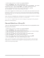
Terminal Type Selection (Group A)
The Omni reader is set at the factory to interface as a PC/AT Keyboard
Wedge. To change this setting to permit the Omni to operate without an external keyboard (as with a touch screen or laptop computer), please follow these
steps:
01 for PC/AT Keyboard Wedge
42 for PC boot-up without external keyboard
6
1. Enter GROUP SETUP MODE by typing /E/D/FA.
2. Press <ENTER>. The reader should beep twice.
3. For the keyboard-less (PC boot-up) feature, type 4 <ENTER>. The reader
should beep twice. Type 2 <ENTER>. The reader should beep twice.
4. Save the changes and exit the Group Setup Mode by typing
AZ <ENTER>. The reader should beep four times.
Note: When configured to Terminal Type 42, the reader can work without an external
keyboard. It will be necessary to power down and restart the Omni after unplugging
the keyboard. To set up, you may plug a keyboard into the keyboard end of the wedge
cable at any time.
Note: The review command (AY) will display the version number and date in addition
to the terminal type setting while the reader is in setup mode.
The “reset all” command (AW) will return settings for all groups to their group defaults (as set at the factory).
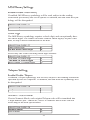
General Selections (Group B)
The basic operating parameters of the Omni reader can be programmed with
this group of selections.
1. Enter GROUP SETUP MODE by typing /E/D/FB .
2. Press <ENTER>. The reader should beep twice.
3. Type the two-character selection code for the feature you wish to change.
4. Press <ENTER>. The reader should beep twice.
5. Type the one-character code for the change you wish to make.
6. Press <ENTER>. The reader should beep twice.
7. Save the setting and exit the Group Setup Mode by typing BZ.
8. Press <ENTER>. The reader should beep four times.
Note: To review the group’s current setting(s), type BY<ENTER> while in Group
Setup Mode. To reset the current setting(s) to its group default, type BX<ENTER>
while in the Group Setup Mode.
7
EXAMPLE:
To set the current settings to the group default, enter:
/E/D/FB<ENTER>BX<ENTER>BZ<ENTER>
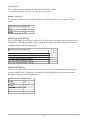
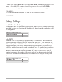
Beep Volume
The beep volume can be adjusted to two different levels, or turned off entirely.
SELECTION CODE: B1
Off
0
Low
1
High
2
Intercharacter Delay
This is the time period the reader will wait before sending the next successive
character. Certain terminals and computers require an intercharacter delay to
simulate human keyboard entry.
SELECTION CODE: B2
2 ms intercharacter delay
5 ms intercharacter delay
10 ms intercharacter delay
20 ms intercharacter delay
50 ms intercharacter delay
100 ms intercharacter delay
0
1
2
3
4
5
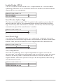
Interblock Delay
This is the time period the reader will wait before transmitting the next successive data block. Some host systems need additional time between data
blocks to process the information.
SELECTION CODE: B3
0 ms
0
10 ms
1
30 ms
2
100 ms
3
300 ms
4
1 second
5
8
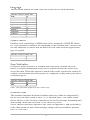
Language
This selection defines the scan code sent to the host for each character.
SELECTION CODE: B4
U.S.
0
U.K.
1
Swiss
2
Swedish
3
Spanish
4
Norwegian
5
Italian
6
German
7
French
8
Japanese
9
Code/Track ID
Each bar code symbology or MSR track can be assigned a CODE ID character. This character is added to the beginning of the scanned data. The host can
use this character to ensure that the data received came from the appropriate
type of symbol.
SELECTION CODE: B5
On
A
Off
B
Scan Verification
In order to insure accuracy of scanned data from poor-contrast bar code
labels, a second confirmation swipe can be required before the reader will
accept the data. When this option is enabled the reader requires the card to be
swiped a second time and both swipes are compared. If they match, the data is
considered good.
SELECTION CODE: B6
On
A
Off
B
Note: This function applies to bar codes only.
Function Code
The standard computer keyboard contains more keys than are supported by
the ASCII code table (such as the F1-F12 function keys). The Omni reader
allows the key codes for these functions to be used in message formatting and
data editing. When this selection is ON, these key codes
can be entered from the Function Code Table in Appendix C and be included
in the data stream as part of the message string (such as preambles, postambles, or Code IDs).
9
SELECTION CODE: B7
On
A
Off
B
Code ID Definition (Group I)
If the Code ID option is enabled in General Setup, the user can select the
character used to identify each symbology.
1. Enter CODE ID DEFINITION SETTINGS MODE by typing /E/D/FI.
2. Press <ENTER>. The reader should beep twice.
3. Enter the characters in the left column to select the symbology.
4. Press <ENTER>. The reader should beep twice.
5. Enter one character for the new ID.
a
b
c
d
e
f
g
h
i
j
k
l
m
n
UPC-A
UPC-E
EAN-8
EAN-13
Code 39
Interleaved 2 of 5
Industrial 2 of 5
Code 128
MSI/Plessey
Codabar
MSR Track 1
MSR Track 2
MSR Track 3
Telepen
Default = a
Default = b
Default = c
Default = d
Default = e
Default = f
Default = g
Default = h
Default = i
Default = j
Default = k
Default = l
Default = m
Default = n
6. Press <ENTER>. The reader should beep twice.
7. Save the change and exit the group setup mode by entering IZ<ENTER>.
The reader should beep four times.
Note: To review the group’s current setting(s), type IY<ENTER> while in the Group
Setup Mode. To reset the current setting(s) to its group default, type IX<ENTER>
while in the Group Setup Mode.
EXAMPLE:
To change Code ID for Code 128 from h to w, enter:
/E/D/FI<ENTER>h<ENTER>w<ENTER>IZ<ENTER>
10
Bar Code Message Formatting Selections (Group C )
Scanned bar code data can be formatted with the addition of preambles,
postambles, and terminator characters. The settings below will augment bar
code data scanned by the Omni. A fully-formatted message block reflects the
following model:
{Preamble}{Code ID}{Data}{Terminator}{Postamble}
1. Enter BAR CODE MESSAGE FORMATTING SETUP MODE by typing
/E/D/FC.
2. Press <ENTER>. The reader should beep twice.
3. Type the two-character selection code for the feature you wish to change.
4. Press <ENTER>. The reader should beep twice.
5. Type the one-character code for the change you wish to make.
6. Press <ENTER>. The reader should beep twice.
7. Save the change and exit the Bar Code Setup Mode by typing CZ.
8. Press <ENTER>. The reader should beep four times.
Note: To review the group’s current setting(s), type CY<ENTER> while in the setup
mode. To reset the current setting(s) to its group default, type CX<ENTER> while in
Bar Code Setup Mode.
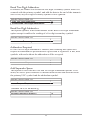
Bar Code Terminator Character
Enter and Line Feed, Enter, Line Feed, or None: For some applications, it
may be convenient to end a string of bar code scan data with a terminator
character. For example, with keyboard entry, it is common to have the operator signify the end of the data input with the “Enter” keystroke. The terminator character serves this function.
SELECTION CODE: C1
ENTER and Line Feed
ENTER
Line Feed
None
A
B
C
D
EXAMPLE:
To set the bar code terminator character to Line Feed, enter:
/E/D/FC<ENTER>C1<ENTER>C<ENTER>CZ<ENTER>
11
Bar Code Preamble
0 to 16 ASCII characters: The bar code preamble is a string of characters that
can be added to the beginning of scanned bar code data. These can be special
characters for identifying a specific scanning station, to format a message
header expected by the receiving host, or a function key from the Function
Code Tables in Appendix C.
SELECTION CODE: C2
One Character or Function Key at a time
Bar Code Postamble
0 to 16 ASCII characters: The bar code postamble serves the same purpose
as the preamble, except it is added to the end of the scanned data after any
terminator characters.
SELECTION CODE: C3
One Character or Function Key at a time
EXAMPLE:
To set a four-character bar code preamble of ABCD, enter:
/E/D/FC<ENTER>C2<ENTER>A<ENTER>B<ENTER>C<ENTER>
D<ENTER>CZ<ENTER>
12
Magnetic Stripe Formatting Selections (Group D)
Magnetic stripe output can also be formatted with the addition of preambles,
postambles, and terminator characters. The settings below will augment magnetic stripe data read by the Omni. A fully-formatted message block reflects
the following model:
{Preamble}{T1 ID}{T1 Data}{Track Separator}{T2 ID}{T2 Data}{Track
Separator}{T3 ID}{T3 Data}{Terminator}{Postamble}
1. Enter MAGNETIC STRIPE FORMATTING SETUP MODE by typing
/E/D/FD.
2. Press <ENTER>. The reader should beep twice.
3. Type the two-character selection code for the feature you wish to change.
4. Press <ENTER>. The reader should beep twice.
5. Type the one-character code for the change you wish to make.
6. Press <ENTER>. The reader should beep twice.
7. Save the change and exit the Magnetic Stripe Setup Mode by typing DZ.
8. Press <ENTER>. The reader should beep four times.
Note: To review the group’s current setting(s), type DY<ENTER> while in the Magnetic Stripe Formatting Setup Mode. To reset the current setting(s) to its group default,
type DX<ENTER> while in Formatting Mode.
Magnetic Stripe Terminator Character
Enter and LF, Enter, Line Feed, or None: For some applications, it may be
convenient to end a string of magnetic stripe data with a terminator character.
For example, with keyboard entry, it is common to have the operator signify
the end of the data input with the “Enter” keystroke. The terminator character
serves this function.
SELECTION CODE: D1
ENTER and Line Feed
ENTER
Line Feed
None
A
B
C
D
EXAMPLE:
To set the magnetic stripe terminator character to Line Feed, enter:
/E/D/FD<ENTER>D1<ENTER>C<ENTER>DZ<ENTER>
13
Magnetic Stripe Preamble
0 to 16 ASCII characters: The magnetic stripe preamble is a string of characters that can be added to the beginning of magnetic stripe data. These can
be special characters for identifying a specific reading station, to format a
message header expected by the receiving host, or a function key from the
Function Code Tables in Appendix C.
SELECTION CODE: D2
One Character or Function Key at a time
Magnetic Stripe Postamble
0 to 16 ASCII characters: The magnetic stripe postamble serves the same
purpose as the preamble, except it is added to the end of the read data after
any terminator characters.
SELECTION CODE: D3
One Character or Function Key at a time
EXAMPLE:
To set a four-character magnetic stripe preamble of ABCD, enter:
/E/D/FD<ENTER>D2<ENTER>A<ENTER>B<ENTER>C<ENTER>
D<ENTER>DZ<ENTER>
14
Bar Code Selections
Bar code selections for the Omni are separated into two groups: Industrial
and Retail. Industrial bar codes may contain a variable number of characters.
Retail bar codes always contain a specific number of characters.
Industrial Bar Codes (Group F)
1. Enter INDUSTRIAL BAR CODE SETUP MODE by typing /E/D/FF.
2. Press <ENTER>. The reader should beep twice.
3. Type the two-character selection code for the bar code symbology you wish
to change.
4. Press <ENTER>. The reader should beep twice.
5. Type the one-character code for the change you wish to make.
6. Press <ENTER>. The reader should beep twice.
7. Save the change and exit the Industrial Bar Code Setup Mode by typing
FZ.
8. Press <ENTER>. The reader should beep four times.
Note: To review the group’s current setting(s), type FY<ENTER> while in the Industrial Bar Code Setup Mode. To reset the current setting(s) to its group default, type
FX<ENTER> while in Industrial Bar Code Setup Mode.
Minimum and Maximum Length Options
You can set minimum and maximum length standards for a particular industrial bar code symbology. (You cannot set a minimum or maximum length for
a retail bar code.)
Minimum length sets the minimum number of data characters that will be
accepted for this symbology. If the minimum length is set higher than the
maximum length, all readings will be rejected.
Maximum length sets the maximum number of data characters that will be
accepted for this symbology. If the maximum length is set lower than the
minimum length, all readings will be rejected.
To set the minimum and maximum length for a particular symbology:
1. Enter Setup Mode by typing /E/D/FF.
2. Press <ENTER>. The reader should beep twice.
3. Enter the selection code for the particular symbology selected (such as
F4<ENTER> for Code 128). The reader should beep twice.
4. Enter FU<ENTER> for minimum or FV<ENTER> for maximum. The
reader should beep twice.
15
5. Enter one digit <ENTER> one digit <ENTER> from the keyboard. (The
range is 01 to 60). The reader should beep twice after each <ENTER>.
6. Save and exit by typing FZ<ENTER>. The reader should beep four times.
EXAMPLE:
To set the maximum length of a Code 39 bar code to 12, enter:
/E/D/FF<ENTER>F1<ENTER>FV<ENTER>1<ENTER>2<ENTER>
FZ<ENTER>
Code 39 Settings:
Enable/Disable Code 39
If enabled, Code 39 symbology will be read, subject to the reading restrictions
specified by this set of options. If disabled, the data from the symbology will
be disregarded.
SELECTION CODE: F1
Code 39 Enable
Code 39 Disable
A
B
Full ASCII
Standard Code 39 symbology supports only 43 characters. This can be expanded by using character pairs to identify the full ASCII 128 character set.
When this option is ON, the reader will search for these character pairs and
transmit only the Full ASCII single character equivalent to the host. If Full
ASCII is enabled and used to read a standard Code 39 symbol, any combination of the defined character pairs will be reported to the host as the single
character equivalent. When this option is OFF and a Full ASCII Code 39
symbol is scanned, the reader will report each of the characters in the Full
ASCII pair as individual characters. The reader has no way of telling if the
symbol is encoded in standard Code 39 or Full ASCII Code 39.
SELECTION CODE: F1
Full ASCII On
Full ASCII Off
C
D
16
Check Digit
When Check Digit is selected, the reader takes the last character in the decoded data stream as a check digit. It then calculates the correct check digit
for the remaining data and compares it to the last data character. If it is the
same, the data is accepted. If not, the data is rejected. With the Calculate and
Send Check Digit option, the reader will send the check digit as part of the
data stream. If the Calculate but Do Not Send Check Digit option is selected,
the reader will strip it from the data stream before transmission. If the Check
Digit is not calculated, the reader will assume the last data character read
from the symbol is part of the data stream and will not make a comparison
test.
SELECTION CODE: F1
Do Not Calculate Check Digit but Send Whole Data Stream
Calculate and Send Check Digit
Calculate but Do Not Send Check Digit
Send Start/Stop Characters
E
F
G
A unique character is used as the first and last character in a Code 39 symbol.
It is printed as an asterisk (*). Some applications require that these characters
be transmitted with the data while others specify that they must not be sent.
SELECTION CODE: F1
Send Start/Stop
Do Not Send Start/Stop
H
I
EXAMPLE:
To disable the Full ASCII Code 39, enter:
/E/D/FF<ENTER>F1<ENTER>D<ENTER>FZ<ENTER>
17
Interleaved 2 of 5 Settings:
Enable/Disable Interleaved 2 of 5
If enabled, Interleaved 2 of 5 symbology will be read, subject to the reading restrictions specified by this set of options. If disabled, the data from the
symbology will be disregarded.
SELECTION CODE: F2
Interleaved 2 of 5 Enable
Interleaved 2 of 5 Disable
A
B
Fixed Length
Interleaved 2 of 5 symbols are commonly printed in a fixed format containing a fixed number of characters. If this option is ON, the first Interleaved 2
of 5 symbol scanned after power up will set the length of any other symbols
scanned afterwards. If the succeeding scans do not match the length of the
first scan, the scan is rejected by the reader. Power must be reset before an
Interleaved 2 of 5 symbol of a different length will be accepted.
SELECTION CODE: F2
Turn On Fixed Length
Turn Off Fixed Length
C
D
Check Digit
When Check Digit is selected, the reader takes the last character in the decoded data stream as a check digit. It then calculates the correct check digit
for the remaining data and compares it to the last data character. If it is the
same, the data is accepted. If not, the data is rejected. With the Calculate and
Send Check Digit option, the reader will send the check digit as part of the
data stream. If the Calculate but Do Not Send Check Digit option is selected,
the reader will strip it from the data stream before transmission. If the Check
Digit is not calculated, the reader will assume the last data character read
from the symbol is part of the data stream and will not make a comparison
test.
SELECTION CODE: F2
Do Not Calculate Check Digit but Send Whole Data Stream
Calculate and Send Check Digit
Calculate but Do Not Send Check Digit
18
E
F
G
Industrial 2 of 5 Settings:
Enable/Disable Industrial 2 of 5
If enabled, Industrial 2 of 5 symbology will be read, subject to the reading
restrictions specified by this set of options. If disabled, the data from the symbology will be disregarded.
SELECTION CODE: F3
Industrial 2 of 5 Enable
Industrial 2 of 5 Disable
A
B
Fixed Length
Industrial 2 of 5 symbols are commonly printed in a fixed format containing a fixed number of characters. If this option is ON, the first Interleaved 2
of 5 symbol scanned after power up will set the length of any other symbols
scanned afterwards. If the succeeding scans do not match the length of the
first scan, the scan is rejected by the reader. Power must be reset before an
Interleaved 2 of 5 symbol of a different length will be accepted.
SELECTION CODE: F3
Turn On Fixed Length
Turn Off Fixed Length
C
D
Check Digit
When Check Digit is selected, the reader takes the last character in the decoded data stream as a check digit. It then calculates the correct check digit
for the remaining data and compares it to the last data character. If it is the
same, the data is accepted. If not, the data is rejected. With the Calculate and
Send Check Digit option, the reader will send the check digit as part of the
data stream. If the Calculate but Do Not Send Check Digit option is selected,
the reader will strip it from the data stream before transmission. If the Check
Digit is not calculated, the reader will assume the last data character read
from the symbol is part of the data stream and will not make a comparison
test.
SELECTION CODE: F3
Do Not Calculate Check Digit but Send Whole Data Stream
Calculate and Send Check Digit
Calculate but Do Not Send Check Digit
19
E
F
G
FEBRABAN Conversion:
If enabled, the original 44-digit Interleaved 2 of 5 data will be converted to
48- digit FEBRABAN code. Otherwise, the original 44-digit data will not be
changed.
SELECTION CODE: F3
Convert to FEBRABAN Code
H
Do Not Convert to FEBRABAN Code I
Code 128 Setting:
Enable/Disable Code 128
If enabled, Code 128 symbology will be read, subject to the reading restrictions specified by this set of options. If disabled, the data from the symbology
will be disregarded.
SELECTION CODE: F4
Code 128 Enable
Code 128 Disable
A
B
Note: The Check Digit is manditory for Code 128.
20
Codabar Settings:
Enable/Disable Codabar
If enabled, Codabar symbology will be read, subject to the reading restrictions specified by this set of options. If disabled, the data from the symbology
will be disregarded.
SELECTION CODE: F5
Codabar Enable
Codabar Disable
A
B
Send Start/Stop Characters
Codabar uses the A, B, C, and D characters as Start and Stop characters, giving 16 unique Start/Stop character combinations. Some applications require
that these characters be transmitted with the data while others specify that
they must not be sent.
SELECTION CODE: F5
Send Start/Stop
Do Not Send Start/Stop
C
D
Check Digit
When Check Digit is selected, the reader takes the last character in the decoded data stream as a check digit. It then calculates the correct check digit
for the remaining data and compares it to the last data character. If it is the
same, the data is accepted. If not, the data is rejected. With the Calculate and
Send Check Digit option, the reader will send the check digit as part of the
data stream. If the Calculate but Do Not Send Check Digit option is selected,
the reader will strip it from the data stream before transmission. If the Check
Digit is not calculated, the reader will assume the last data character read
from the symbol is part of the data stream and will not make a comparison
test.
SELECTION CODE: F5
Do Not Calculate Check Digit but Send Whole Data Stream
Calculate and Send Check Digit
Calculate but Do Not Send Check Digit
21
E
F
G
MSI/Plessey Settings:
Enable/Disable MSI/Plessey
If enabled, MSI/Plessey symbology will be read, subject to the reading
restrictions specified by this set of options. If disabled, the data from the symbology will be disregarded.
SELECTION CODE: F7
MSI/Plessey Enable
MSI/Plessey Disable
A
B
Check Digit
The MSI/Plessey symbology requires a check digit, and can optionally have
two check digits. The reader can either send the check digit(s) as part of the
data, or strip it before transmission to the host.
SELECTION CODE: F7
Send Check Digit
Do Not Send Check Digit
C
D
Select only one of the following check digit schemes:
SELECTION CODE: F7
One Mod 10 Check Digit
Two Mod 10 Check Digits
Mod 10/Mod 11 Check Digits
E
F
G
Telepen Setting:
Enable/Disable Telepen
If enabled, Telepen symbology will be read, subject to the reading restrictions
specified by this set of options. If disabled, the data from the symbology will
be disregarded.
SELECTION CODE: F8
Telepen Enable
Telepen Disable
A
B
Numeric / ASCII Mode
If set to Numeric Mode, each original Telepen code will be translated into
2-digit numeric pair. Otherwise, ASCII or Numeric data will be sent out
accor-ding to the AIM specification.
SELECTION CODE: F8
Numeric Mode
ASCII Mode
C
D
22
Retail Bar Codes (Group G)
Retail bar codes are based on the Uniform Code Council product code encoding algorithms. These are commonly referred to as the UPC/EAN symbologies.
1. Enter RETAIL BAR CODE SETUP MODE by typing /E/D/FG.
2. Press <ENTER>. The reader should beep twice.
3. Type the two-character selection code for the bar code symbology you wish
to modify.
4. Press <ENTER>. The reader should beep twice.
5. Type the one-character code for the change you wish to make.
6. Press <ENTER>. The reader should beep twice.
7. Save the change and exit the Group Setup Mode by typing
GZ <ENTER>. The reader should beep four times.
Note: To review the current setting(s), type GY<ENTER> while in Group Setup Mode.
To reset the current setting(s) to default, type GX<ENTER> while in Group Setup
Mode.
EXAMPLE:
To set the current settings to default, enter:
/E/D/FG<ENTER>GX<ENTER>GZ<ENTER>
UPC Settings:
Enable/Disable UPC-A
UPC-A is a fixed format symbology and there are no variations allowed. If
enabled, UPC-A symbology will be read, subject to the reading restrictions
specified by this set of options. If disabled, the data from the symbology will
be disregarded.
SELECTION CODE: G1
UPC-A Enable
UPC-A Disable
A
B
23
Enable/Disable UPC-E
UPC-E is a special version of the UPC-A specification. It is a fixed format
symbology and there are no variations allowed. If disabled, the data from the
symbology will be disregarded.
SELECTION CODE: G1
UPC-E Enable
UPC-E Disable
C
D
Send Number System Digit
The first encoded digit in the UPC-A symbol is the number system digit. If
enabled, the first digit of the transmitted data stream is the number system
digit followed by the manufacturer’s number. If disabled, then the first digit
transmitted is part of the manufacturer’s number.
SELECTION CODE: G1
Send Number Digit
Do Not Send Number Digit
E
F
Send Check Digit
The check digit is mandatory in the UPC symbology. If enabled, the reader
will send the decoded check digit as the last character in the data stream transmitted. If not, the check character will be suppressed before transmission.
SELECTION CODE: G1
Send Check Digit
Do Not Send Check Digit
G
H
UPC-E Expansion
The UPC-E symbology uses a special algorithm to suppress zeros in the
encoded data. The suppressed information can be restored by either the Omni
reader or the host system. If enabled, the reader will restore the data to its
original format. If the host system is set up to do the expansion, then this option should not be used.
SELECTION CODE: G1
Expand UPC-E
Do Not Expand UPC-E
I
J
24
Read Two-Digit Addendum
If enabled, the reader will decode the two-digit secondary symbol when it is
scanned with the primary symbol, and add the data to the end of the transmission. If not, any two-digit secondary symbol will be ignored.
SELECTION CODE: G1
Read Two-Digit Addendum
Do Not Read Two-Digit Addendum
K
L
Read Five-Digit Addendum
This option operates in the same manner as the Read Two Digit Addendum
option except it enables the reading of a five digit secondary symbol.
SELECTION CODE: G1
Read Five-Digit Addendum
Do Not Read Five-Digit Addendum
M
N
Addendum Required
If a two or five-digit addendum is enabled, then enabling this option will
require an addendum be present before a good read is registered. If not, then
symbols with and without the addendum will be accepted.
SELECTION CODE: G1
Addendum Required
Addendum Not Required
O
P
Add Separator Space
This option is used with the Two and Five-Digit Addendum options. If enabled, an ASCII space character is inserted between the data decoded from
the primary UPC symbol and the addendum symbol.
SELECTION CODE: G1
Add Space Separator
Not Add Space Separator
Q
R
Convert UPC-A to EAN-13
SELECTION CODE: G1
Do Not Convert to EAN-13
Convert to EAN-13
S
T
25
EAN Settings:
Enable/Disable EAN-13
EAN-13 is a fixed format symbology and there are no variations allowed. If
enabled, EAN-13 symbology will be read, subject to the reading restrictions
specified by this set of options. If disabled, the data from the symbology will
be disregarded.
SELECTION CODE: G2
EAN-13 Enable
EAN-13 Disable
A
B
Enable/Disable EAN-8
If enabled, EAN-8 symbology will be read, subject to the reading restrictions
specified by this set of options. If disabled, the data from the symbology will
be disregarded.
SELECTION CODE: G2
EAN-8 Enable
EAN-8 Disable
C
D
Send Induced Country Code Character
The EAN symbology adds an extra digit to the beginning of the data to create
a two-digit country code. If enabled, the added induced character is the first
character transmitted. If disabled, the induced character is not transmitted.
SELECTION CODE: G2
Induced Character Enable
Induced Character Disable
E
F
Send Check Digit
The check digit is mandatory in the EAN symbology. If enabled, the reader
will send the decoded check digit as the last character in the data stream transmitted. If not, the check character will be suppressed before transmission.
SELECTION CODE: G2
Send Check Digit
Do Not Send Check Digit
G
H
26
Read Two-Digit Addendum
If enabled, the reader will decode the two-digit secondary symbol when it is
scanned with the primary symbol, and add the data to the end of the transmission. If not, any two-digit secondary symbol will be ignored.
SELECTION CODE: G2
Read Two-Digit Addendum
Do Not Read Two-Digit Addendum
I
J
Read Five-Digit Addendum
This option operates in the same manner as the Read Two Digit Addendum
option except it enables the reading of a five digit secondary symbol.
SELECTION CODE: G2
Read Five-Digit Addendum
Do Not Read Five-Digit Addendum
K
L
Addendum Required
If a two or five-digit addendum is enabled, then enabling this option will
require an addendum be present before a good read is registered. If not, then
symbols with and without the addendum will be accepted.
SELECTION CODE: G2
Addendum Required
Addendum Not Required
M
N
Add Separator Space
This option is used with the Two and Five-Digit Addendum options. If enabled, an ASCII space character is inserted between the data decoded from
the primary UPC symbol and the addendum symbol.
SELECTION CODE: G2
Add Space Separator
Not Add Space Separator
O
P
27
Magnetic Stripe Selections (Group H)
The Omni reader can accept and decode data read from a magnetic stripe. The
parameters for reading the magnetic data can be programmed independently
from any of the bar code selections.
1. Enter MAGNETIC STRIPE SELECTIONS SETUP MODE by typing
/E/D/FH .
2. Press <ENTER>. The reader should beep twice.
3. Type the two-character selection code for the feature you wish to change.
4. Press <ENTER>. The reader should beep twice.
5. Type the one-character code for the change you wish to make.
6. Press <ENTER>. The reader should beep twice.
7. Save the change and exit the Group Setup Mode by typing
HZ <ENTER>. The reader should beep four times.
Note: To review the current setting(s), type HY<ENTER> while in Magnetic Stripe
Selections Setup Mode. To reset the current setting(s) to default, type HX<ENTER>
while in Magnetic Stripe Selections Setup Mode.
Track Selection
There are three tracks on a magnetic stripe card that can contain encoded data.
This option selects the tracks that will be decoded. Note that the magnetic
stripe reader must have heads aligned for reading the specified tracks.
SELECTION CODE: H1
Track 2 Only
Track 1 Only
Track 3 Only
Tracks 1 & 2
Tracks 2 & 3
Any Track
All Tracks
A
B
C
D
E
F
G
Send Start/Stop Sentinel
The tracks of a magnetically-encoded card contain special Start/Stop Sentinel
characters. If this option is enabled, the Start/Stop Sentinel characters will be
transmitted as part of the data stream. If this option is not selected, the Sentinel characters are suppressed before transmission.
28
SELETION CODE: H2
Send Start/Stop Sentinels
Do Not Send Start/Stop Sentinels
A
B
Track Two Send Accout Number Only
Track Two of a magnetically encoded credit card includes the account number
information as well as other information. If this option is selected, all other
data contained on the track is suppressed before transmission.
SELECTION CODE: H3
Track 2 Send Account Number Only
Track 2 Not Limited to Account Number
A
B
Track Separator
One character from the Full ASCII Table: This option allows the user to select
the character used to separate data decoded from each track when using multiple track magnetic stripe readers.
H4<ENTER><SELECTED CHARACTER><ENTER>
Note: For no track separator, enter N. Default is <ENTER>.
Reviewing Configuration Settings
The reader’s current settings can be reviewed by following these steps:
1. Locate the group that contains the settings you want to review.
2. On an AT-compatible computer, enter any document editor. (Notepad is
recommend in the Windows environment.)
3. Enter the setup mode for that group by typing /E/D/FX <Enter>. (X in this
case is the single alpha character identified with the group located in Step 1.)
4. The reader will respond with two beeps after <ENTER> is depressed.
5. Review the settings for the group by typing XY<ENTER>. (X is the same
single alpha character as typed in Step 3.)
6. After <ENTER> is depressed, the reader will display the current settings
for the group onto the screen for user to review, followed by two beeps from
the reader.
7. Exit the setup mode after reviewing the settings by typing XZ <ENTER>.
(X is the same single alpha character as typed in Step 3.)
8. The reader will respond with four beeps.
29
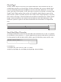
EXAMPLE:
To review the reader’s current settings for the Code 39 bar code, first find
the settings for Code 39 listed in the Industrial Bar Codes setup group. (The
single alpha character group name is F.) Then in Notepad type:
/E/D/FF<ENTER>FY<ENTER>
A sample response is shown below.
Remember to end the review by typing: FZ<ENTER> This will take the
reader out of the setup mode and bring it back into its normal reading mode.
=======================================================
Industrial Bar Code Setting
Code 39
Enabled; Full ASCII Off
Min Length = 01; Max Length = 60; No Check Digit; Stop-Start Send
I 2 0f 5
Enabled; Fixed Length Off
FEBRABAN
Enabled
S 2 of 5
Enabled; Fixed Length Off
Code 128
Enabled
Codabar
Enabled; StopStart Not Send
MSI
Enabled; Check Digit Not Send
Telepen
Enabled, ASCII Mode
Min Length = 01; Max Length = 60; No Check Digit
Min Length = 01; Max Length = 60; No Check Digit
Min Length = 01; Max Length = 60
Min Length = 01; Max Length = 60; No Check Digit
Min Length = 01; Max Length = 60; Check Digit Double Modulo 10
Min Length = 01; Max Length = 60
=======================================================
30
Section 5
DATA EDITING
In addition to adding preambles, postambles, and terminator characters, the
Omni can also rearrange, drop, or add to the data it reads from a bar code or
magnetic stripe. This enables the data to be sent to the host in the exact format
expected by the application software, thus eliminating the need for software
modifications.
To accomplish this, the decoded data is divided into smaller blocks of data
known as “fields.” in accordance with established standards such as ISO,
AAMVA, and CDL.* With these fields of data defined, the order in which
they are sent to the host can be changed. They can also be added or eliminated
as needed.
Specifically, the following functions can be performed:
Validate the Data: Data read from a bar code or magnetic stripe can be
checked for length, matched to a preset value, or restricted to a certain type of
input (i.e., Code 39, Code 128, etc.).
Parse the Data: The data can be divided into separate fields.
Rearrange the Data:
Data The fields that make up one track of data can be
transmitted to the host in any order desired, regardless of the order in which
they occur on the magnetic stripe itself.
Insert Character Strings into the Data:
Data Additional fields of characters can be
created and inserted into the data at any place on any track.
Delete Character Strings from the Data a Record:
Record Fields of characters can be
deleted from the data before it is transmitted to the host.
Search for a Character String:
String Data can be searched for a specified string of
characters. This string of characters can then be deleted, moved, or modified
using other Data Editing commands.
Duplicate Fields:
Fields Fields of data within a track can be duplicated and
transmitted to the host as many times as desired—and in any order desired.
Insert Time Delay:
Delay Time delays can be inserted between fields of data to give
the host time to complete an operation.
* Please see Appendix D for standard magnetic stripe data formats.
31
Data Fields
By separating decoded data into blocks known as “fields,” each block of data
can be treated individually. Fields can also be added to the data, permitting
user-required characters or function keys to be included.
The fields are identified by a one-character ID starting with the character “A”
(up to and including “Z”) in the order they were created. These fields can then
be sent to the host in the order you specified.
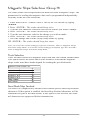
For example, if the credit card data on Track 2 of the magnetic stripe is:
;1234567890123456=9912xxxxxxx?
It is divided into seven fields (A, B, C, D, E, F, and G) as shown below:
;1234567890123456=9912xxxxxxx?
|A|
B
|C| D |
E
|F|
If your application software needs the data sent in the following format:
9912<ENTER>
1234567890123456<ENTER>
You can create that format by selecting only the fields you need, reversing
the order in which they are sent to the host, and then creating a new field
<ENTER> to insert after each field.
We do this by using the fields as defined above and adding a new field:
Field B = 1234567890123456
Field D = 9912
Field G = <ENTER>
and then sending {Field D}{Field H}{Field B}{Field G} to the host.
32
Data Editing Formulas
The set of instructions programmed into the reader to define data fields and
than arrange them into a format is known as the data editing “formula.”
A maximum of four formulas can be resident in the reader’s memory at any
one time. If more than one formula is stored in memory, the reader will apply
the first formula to the decoded data. If the data format matches the format
(credit card, driver’s license, etc.) of the first formula, then it will re-arrange,
add, and drop the data fields as you have indicated and output the reformatted
data to the host.
However, if the data does not match the criteria spelled out in the first
formula, then the criteria of the second formula stored in memory will be
applied. And so on. This process will continue for each of the successive
formulas until a match is found. If no matches are found for any of the
formulas programmed into the reader, then the unedited data record will not
be transmitted to the host by default.
The number of formulas the reader will store is limited by the amount of
memory available. Caution should therefore be used when entering a number
of long formulas, as all might not fit.
33
The Formula Sequence
A basic data editing formula for the Omni has the following structure. (The
optional commands are enclosed in brackets):
CODE ID[LENGTH][MATCH]DIVIDE[ADD]SEND
In other words:
1. Identify the bar code symbologies and/or magnetic stripe tracks to which
this formula will apply.
2. Specify data length parameters (if desired).
3. Specify the characters (if any) you would like to match.
4. Indicate how you want to divide the data record.
5. Add a character string (if desired).
6. Send the edited data record to the host computer.
Several code IDs can be specified following the CODE ID command, and
several ADD commands can be programmed as long as they are grouped
together and placed prior to the SEND command.
Note: If Function Codes are to be used with any of the commands, the Function Code
capability must be enabled by typing /E/D/FB<ENTER>B7<ENTER>
A<ENTER>BZ<ENTER> before entering the Data Editing Setup mode.
34
Using the Data Editing Functions
The data editing function is often applied to driver’s licenses, where the
magnetic stripe contains three tracks of information about the license holder,
and the host application may need only certain details (such as name, address,
and birth date) rather than all the data the stripe holds.
In the AAMVA format, for example, the unedited output for a driver’s license
might look like this:
TRACK 1:
TRACK 2:
TRACK 3:
%CABREA^DOE$JANE$R$^310 S JEFFERSON ST^?
;636014028198457=051219639924?
%!!92870 C F503121BLKBRN D69119980116?
Track 1 contains the license holder’s name and address. Track 2 includes the
expiration date and the holder’s birthdate. Track 3 includes such details as
height, weight, sex, hair, and eye color.
You can identify exactly what fields the various bits of data occupy by
referring to the AAMVA format in Appendix E. Read the data from a sample
license, print it out, and then mark the fields accordingly. Now decide what
fields of data you need, and what fields of data you don’t need. For instance,
if you don’t need eye and hair colors, you can discard this data once it is read
and decoded. You don’t need to send it to the host.
Once you know what data you’ll need for your host application, decide what
order you’ll need it in. Should the name come first? Should the city come
last? Is there other data or formatting you need? If so, you will have to add
fields that contain that data.
Knowing what fields you need to add, drop, and re-arrange will enable you to
make full use of the commands on the following pages.
35
Data Editing Commands
1. Enter DATA EDITING mode by typing /E/D/FJ
2. Press <ENTER>. The reader should beep twice.
3. Type the two-character selection code for the function you wish to enable
or set.
4. Press <ENTER>. The reader should beep twice.
5. Type the command you wish to enter.
6. Press <ENTER>. The reader should beep twice.
7. Continue to add commands to the data editing formula as desired.
8. Save the formula and exit the data editing mode by typing
JZ <ENTER>. The reader should beep four times.
Note: JZ should only being entered at the end of the entire data editing formula, not
after each command. See examples page 41.
Data Editing On/Off
Use this command to turn the Data Editing function on or off.
SELECTION CODE: JA
Data Editing Off
Data Editing On
0
1
EXAMPLE:
To turn the Data Editing function on, enter:
/E/D/FJ<ENTER>JA<ENTER>1<ENTER>JZ<ENTER>
Unmatched Input Send/Do Not Send
This command enables or disables the transmission of data that does not
meet the restrictions of the data editing formula(s). When SEND ALL DATA
is selected, data that does not match any of the formulas will be transmitted
anyway, along with any preambles or postambles. When DO NOT SEND is
selected, unmatched data will not be sent.
SELECTION CODE: JB
If No Formula Matches Data,
Do Not Send Data
If No Formula Matches Data,
Send All Data
0
1
36
Select Code ID(s)
This command designates the bar code symbologies or magnetic stripe tracks
that will be accepted as valid.
SELECTION CODE: JC
UPC-A
UPC-E
EAN-8
EAN-13
Code 39
Interleaved 2 of 5
Industrial 2 of 5
Code 128
MSI/Plessey
Codabar
MSR Track 1
MSR Track 2
MSR Track 3
Telepen
a
b
c
d
e
f
g
h
i
j
k
l
m
n
EXAMPLE:
To designate UPC-A, Code 39, Codabar, and MSR Track 1 as the only valid
sources of data, enter:
... JC<ENTER>a<ENTER>e<ENTER>j<ENTER>k<ENTER> ...
Set Length
Use this command to indicate a minimum and maximum number of
characters allowed for valid data. The first two digits set the minimum
length, and the second two digits set the maximum length. (This command is
optional.)
SELECTION CODE: JD
Two Digits for Minimum Length
Two Digits for Maximum Length
EXAMPLE:
To set the minimum number of characters at six, and the maximum at twelve,
enter:
... JD<ENTER>0<ENTER>6<ENTER>1<ENTER>2<ENTER> ...
37
Match String
This command looks for a “match” between a data string designated in the
data editing formula and a data string in the data scanned by the reader. When
this feature is enabled, the only data sent to the host will be data that contains
the matched data string. The first two digits indicate the position in the
scanned data at which the match is to begin. Up to 60 characters can then be
entered to specify the actual string to be matched. If you need to match more
than one character string, simply add another match command to the formula.
(This command is optional.)
SELECTION CODE: JE
Two Digits for Position at which to Begin Match
Up to 60 Characters for Match String
EXAMPLE:
To begin the match string at position 8 and designate the match string as
ABCDE, enter:
... JE<ENTER>0<ENTER>8<ENTER>A<ENTER>B<ENTER>
C<ENTER>D<ENTER>E<ENTER> ...
This means that input data “1234567ABCDE” will match the data string in
the Match String formula and will therefore be considered valid.
Note: The first position is 01, not 00.
Create a Data Field
This command allows you to create a data field that begins with the first
position in the scanned data and extends a specified number of characters.
For instance, if the new data field is to be eight characters long, the undivided
field of data will be divided into two fields, the first eight characters long, and
the second the remaining data characters.
SELECTION CODE: JF
Two Digits for Position at which First Data Field Ends
EXAMPLE:
In scanned data 15 characters long, to create a first data field of 7 characters
and a second data field of 8 characters, enter:
... JF<ENTER>0<ENTER>7<ENTER> ...
This means that input data “1234567ABCDEFG” will divide into two fields:
1234567 and ABCDEFG.
38
Search for a Data String
This command allows you to create a data field by searching the scanned data
for a data string that matches a data string specified in the formula. If a match
is found, the scanned data will be divided into three fields: the data from the
search start point to the character before the searched data string, the data
string itself, and the data remaining.
SELECTION CODE: JG
Characters that Constitute the Data String to be Searched for
EXAMPLE:
In scanned data, to search for the data string ABCDE, enter:
... JG<ENTER>A<ENTER>B<ENTER>C<ENTER>
D<ENTER>E<ENTER> ...
This means that scanned data “1234567ABCDEFG” will be divided into three
fields: 1234567 and ABCDE and FG.
Add a Data Field
This command allows you to add a character string to scanned data before
transmitting it to the host computer. The character string you add will be
transmitted as a separate data field. (This command is optional.)
SELECTION CODE: JJ
Characters that Constitute the Data String to be Added
EXAMPLE:
In scanned data, to add one data field “abcd” to the scanned data 1234, enter:
... JJ<ENTER>a<ENTER>b<ENTER>c<ENTER>d<ENTER> ...
This means that additional field “abcd” can be added to output data string
abcd and 1234.
39
Set the Sequence in which Data Fields are Sent
This command specifies the order in which data fields are transmitted to the
host. Each separate field is assigned an upper case alpha letter in the order in
which it is created. So the first data field created is A, the second is B, and so
on.
SELECTION CODE: JK
Characters Assigned to Data Fields in the Transmission Order Desired
EXAMPLE:
To transmit fields A, B, and C to the host so that the second and third data
fields are reversed, enter:
... JK<ENTER>A<ENTER>C<ENTER>B<ENTER> ...
This means that data fields A, B, and C will be transmitted as A, C, and B.
Time Delay
In addition to specifying the order in which data fields are transmitted to the
host, you can add a time delay between each field. The amount of time delay
is two digits multiplied by 100 milliseconds. So if the time delay specified is
“02” the time delay will be 200 milliseconds.
SELECTION CODE: JM
Two Digits for Time Delay
Delete One Formula
This command deletes a single formula stored in the reader’s memory. To do
this, you need to know the place the formula is stored in memory. In other
words, if the formula to be deleted is the third formula stored in the reader’s
memory, then you’ll need to enter the number 3.
SELECTION CODE: JS
One Digit to Indicate which Formula to Delete
40
Reset Data Editing Group
This command will clear the reader’s memory of all formulas, disable the
Data Editing feature, and send the original data with the preamble, postamble,
and terminator specified.
SELECTION CODE: JX
EXAMPLE:
To delete all data editing formulas from the reader’s memory, enter:
/E/D/FJ<ENTER>JX<ENTER>JZ<ENTER>
Review Configurations
This command allows you to view all the data editing formulas stored in the
reader’s memory, as well as all other data editing settings.
SELECTION CODE: JY
EXAMPLE:
To view all data editing formulas in the reader’s memory, enter:
... JY<ENTER> ...
Exit Data Editing Mode
Remember to enter JZ<ENTER> to save your settings and exit the Data
Editing mode.
SELECTION CODE: JZ
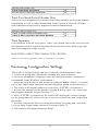
Omni Data Flow
The Omni reader processes scanned data in the following order:
1. Raw data is scanned and decoded and placed in an ASCII character format
in the reader’s memory.
2. The bar code symbology and magnetic stripe track tests (maximum/
minimum length, check digit, send sentinels, etc.) are applied to the data.
3. Following the successful completion of these tests, the data is compared to
each data editing formula stored in memory.
4. If the data matches one of the data editing formulas, it is processed and
sent to the output port. If the data does not match any of the formulas and the
UNMATCHED INPUT function is set to DO NOT SEND, the data will be
discarded.
41
5. If UNMATCHED INPUT is set to SEND, the unmatched data is passed
on to the message processing section of the reader, where any previouslydefined postamble, preamble, and terminator characters are added before
the data is sent to the output port.
Examples
EXAMPLE ONE
76440057320712
Symbology Code 128
Desired Output: Divide the input data record into two fields with one consisting of the first six digits and the second containing the remaining data.
The output should have a <ENTER> inserted after each field.
Formula
ID h C 06 A <ENTER> SEND ACBC
Field List
Field A 764400
Field B 57320712
Field C <ENTER>
Prior to data editing, enable the Function Code Selection on page 9.
Keystroke Sequence
/E/D/FJ<ENTER>
JA<ENTER>1<ENTER>
JC<ENTER>h<ENTER>
Enter Data Editing Setup
Enable Data Editing
Enter Code ID as h (for Code 128)
Define first six characters as Field A,
and remaining data as Field B
Enter Add Field C as the <ENTER> key
Define Field Sending Sequence of ACBC
Save Exit Setup
Output Data
JF<ENTER>0<ENTER>
6<ENTER>
JJ<ENTER>\<ENTER>
JK<ENTER>A<ENTER>
C< ENTER>B<ENTER>
C<ENTER>
JZ<ENTER>
764400<ENTER>
57320712<ENTER>
42
EXAMPLE TWO
*AST798X*
Symbology Code 39
Desired Output: The input record must be Code 39 and be exactly seven
characters in length with the seventh character being an “X”. It is divided into
three fields; the first three characters, the next three characters, and the last
character. The output should reverse the order of the first two fields, delete
the last character, and add an F1 function code at the end of each field. In
addition, a time delay of 900 milliseconds should be added between the fields
(after the F1) and another delay of 2000 milliseconds added to the end of the
record.
Formula
ID e LEN 07 07 M 07 X C 03 C 03 A <F1>
SEND BD DLY 09 AD DLY 20
Field List
Field A AST
Field B 798
Field C X
Field D <F1>
Prior to data editing, enable the Function Code Selection on page 9.
Keystroke Sequence
/E/D/FJ<ENTER>
JA<ENTER>1<ENTER>
JC<ENTER>e<ENTER>
JD<ENTER>0<ENTER>7<ENTER>0
< ENTER >7<ENTER>
Enter Match and 07X
JE<ENTER>0<ENTER>7<ENTER>
X<ENTER>
Enter Count and 03
JF<ENTER>0<ENTER>3<ENTER>
Enter Count and 03
JF<ENTER>0<ENTER>3<ENTER>
Enter Add Field & <F1> character JJ<ENTER>\F1<ENTER>
Enter Field Sequence and BD
JK<ENTER>B<ENTER>D<ENTER>
Enter Add Delay and 09
JK<ENTER>JM<ENTER>0<ENTER>
9<ENTER>
Enter Field Sequence and AD
JK<ENTER>A<ENTER>D<ENTER>
Enter Add Delay and 20
JK<ENTER>JM<ENTER>2<ENTER>
0<ENTER>
Enter Exit Setup
JZ<ENTER>
Enter Data Editing Setup
Enter Data Editing and Enable
Enter Code ID and e (for Code 39)
Enter Length and 0707
Output Data
798<<F1>>.9s delay AST<<F1>>
2s delay
43
EXAMPLE THREE
%B0123774965^FISH/MARY^96124379F?
MSR Track 1 data
Desired Output: Divide it up into seven fields so that the 1st field is the first
two characters, 2nd field is all characters from the first field to the first “^”
character, 3rd field is the first “^” character, 4th field is the data between “^”
marks, 5th field is the next “^” character, 6th field is the next four characters,
7th field is the remaining characters. In addition, an <ENTER> is inserted
between fields in the data output record. Only the 4th, 2nd, and 6th fields are
outputted.
Formula
Field List
ID k C 02 S ^ S ^ C04 A<ENTER> SEND
DHBHFH
Field A
%B
Field B
0123774965
Field C
^
Field D
FISH/MARY
Field E
^
Field F
9612
Field G
4379F?
Field H
<ENTER>
Prior to data editing, enable the Function Code Selection on page 9.
Keystroke Sequence
/E/D/FJ<ENTER>
JA<ENTER>1<ENTER>
JC<ENTER>k<ENTER>
JF<ENTER>0<ENTER>
2<ENTER>
Enter Search String and the ^ character
JG<ENTER>^<ENTER>
Enter Search String and the ^ character
JG<ENTER>^<ENTER>
Enter Count and 04
JF<ENTER>0<ENTER>
4<ENTER>
Enter Add Field & the <ENTER> character JJ<ENTER>\<ENTER>
Enter Field Sequence and DHBHFH
JK<ENTER>D<ENTER>
H<ENTER>B<ENTER>
H<ENTER>F<ENTER>
H<ENTER>
Enter Exit Setup
JZ<ENTER>
Enter Data Editing Setup
Enter Data Editing and Enable
Enter Code ID and k (for MSR Track 1)
Enter Count and 02
Output Data
FISH/MARY<ENTER>
0123774965<ENTER>
9612<ENTER>
44
Section 6
TROUBLESHOOTING
The Omni reader is easy to install and use. Most problems encountered can be
attributed to:
·
·
·
·
Incorrect Interface Cabling
Incorrect Configuration Setup
Bad Magnetic Stripe Quality
Poor Bar Code Printing Quality
General Procedures
The troubleshooting process can be simplified by following these simple diagnostic procedures.
1. The unit should emit two beeps when power is first applied and the LED
should turn green. If this does not happen, then the unit is not receiving power
or did not power up correctly.
2. Once it has been confirmed that the unit is correctly powered, try swiping a
credit card. If the decode is successful, the LED will turn amber and the data
will be sent out, accompanied by a beep. The LED will turn amber for a short
moment and then back to green after the data has been transferred. If the decode fails, the LED will turn red for about 2 seconds to indicate a “bad read”
with no beep or one beep if just one track fails.
3. Once the unit has indicated a “good read,” proceed to check the interface
cabling connections.
45
Keyboard Interface Problems
Installation of the reader is generally trouble free, but there are some things to
watch for if you are experiencing problems.
Do you have the proper cable?
Most modern computers and terminals use a PC/XT/AT-compatible keyboard.
However, the cable connecting it to the keyboard port may have variations
in either the signal pins or the connector itself. Make sure that you have the
proper cable for the computer/terminal with which you are interfacing.
Does the keyboard work?
Since the data from the keyboard must pass through the reader, the cabling
connections are not correct if the keyboard is not operational.
Can the host computer accept the data fast enough?
Some computers and terminals are expecting the data rate from the keyboard
port to come in at a keystroke rate, and might not be able to accept it as fast
as the reader is transmitting. Try adjusting the intercharacter delay to simulate
the effects of keystroke delays.
Does the keyboard port supply enough power?
Most computers supply enough power to the keyboard port to operate the
reader. Occasionally you will find keyboard ports that supply only a very
limited amount of power. See if the LED is lighting at full intensity; a lighterthan-usual green (or a red showing as orange) could indicate a “low power”
condition.
46
Scanning Configuration Problems
One common problem is incorrect configuration setup. You may be trying
to read a bar code with the check digit enabled, but the bar code was printed
without it. The default settings for the reader are the most frequently-used
parameters. If these work, use them. That way, when someone inadvertently
changes the settings, they can be reset by entering the return to default codes.
If you must use different settings, it is advisable to make a master sheet with
the desired configuration keystrokes in the proper order. The operator can
then enter them in sequential order to configure the reader as desired.
1. Is the bar code properly positioned on the card?
The reader is designed for a bar code centered 0.49” (12.5 mm) from the bottom of the card.
2. Is the bar code printed in good quality (and straight)?
3. Does the bar code have a security tape or mask covering it?
If so, be sure to use a model with an infra red light source.
4. Is the proper bar code symbology enabled?
Each symbology can be individually enabled or disabled. It is sometimes
desirable to enable only those that will be used, thereby eliminating any errors
due to the operator scanning the wrong bar code symbol.
5. Do the selected bar code symbology format options match the symbol?
The scanned data from each bar code symbology can be restricted to eliminate the scanning of unwanted symbols. The restrictions are individually set
for each symbology.
6. Is the desired track on the magnetic stripe enabled?
7. Does the output data format match the requirements of the application
software?
8. Has the magnetic stripe been encoded in a standard format?
Finally, if the reader gives the correct LED and beep indications but no data is
transmitted to the host, check the cable connection.
47
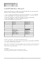
Appendix A
BAR CODE DEFAULT SETTINGS
The Omni reader is shipped from the factory with the following bar code
default settings already programmed:
Terminal Selection (Group A)
Type
IBM PC/AT Keyboard Wedge
General Selection (Group B)
Beep Volume
Intercharacter Delay
Interblock Delay
Language
Code ID
Scan Verification
Function Code
High
5 milliseconds
0 milliseconds
United States
Off
Off
Off
Bar Code Message Formatting (Group C)
Terminator Character
<ENTER>
Preamble
None
Postamble
None
Magnetic Stripe Message Formatting (Group D)
Terminator Character
<ENTER>
Preamble
None
Postamble
None
Magnetic Stripe Selections (Group H)
Track Selection
Start/Stop Selection
Track 2 Send Account # Only
Track Separator
Any Track
Send
Not Limited to Account #
<ENTER>
Data Editing (Group J)
Edit On/Off
Unmatched Input
Off
Do Not Send
48
INDUSTRIAL BAR CODES (Group F)
Code 39
Enabled
Full ASCII
On
Check Digit
Off
Send Check Digit
No
Send Start/Stop
No
Minimum Length
1
Maximum Length
60
Interleaved 2 of 5
Fixed Length
Check Digit
Minimum Length
Maximum Length
Enabled
Off
None
4
60
Industrial 2 of 5
Fixed Length
Check Digit
Minimum Length
Maximum Length
Enabled
Off
None
1
60
Febraban
Convert
Code 128
Minimum Length
Maximum Length
Enabled
1
60
Codabar
Send Start/Stop
Check Digit
Minimum Length
Maximum Length
Enabled
No
None
2
60
MSI/Plessy
Send Check Digit(s)
Check Digits
Minimum Length
Maximum Length
Enabled
No
Modulo 10/Modulo 10
1
60
Telepen
Numeric Mode
Enabled
On
49
RETAIL BAR CODES (Group G)
UPC-A, -E
Send Number System Digit
Send Check Digit
Expand UPC-E
Read 2, 5 Digit Addendum
Addendum required
Add Addendum Separator
Send UPC-A as EAN-13
Enabled, Enabled
Yes
Yes
No
No, No
Yes
Yes
No
EAN-13, -8
Send Induced Country Code Digit
Send Check Digit
Read 2, 5 Digit Addendum
Addendum Required
Add Addendum Separator
Enabled, Enabled
Yes
Yes
No, No
Yes
Yes
Code ID
UPC-A
UPC-E
EAN-8
EAN-13
Code 39
Interleaved 2 of 5
Industrial 2 of 5
Code 128
MSI/Plessey
Codabar
MSR Track 1
MSR Track 2
MSR Track 3
Tepelen
a
b
c
d
e
f
g
h
i
j
k
l
m
n
50
Appendix B
MAGNETIC STRIPE DATA OUTPUT FORMAT
The Omni reader is shipped from the factory with the following magnetic
stripe default settings already programmed:
Magnetic Track Basic Data Output Format
Track 1: <SS1><T1 Data><ES><TS>
Track 2: <SS2><T2 Data><ES><TS>
Track 3: <SS3><T3 Data><ES><Terminator>
where: SS1(start sentinel track 1) = %
SS2(start sentinel track 2) = ;
SS3(start sentinel track 3) = ; for ISO, ! for CDL, % for AAMVA
ES(end sentinel all tracks) = ?
<TS> = <ENTER> key on keyboard
Terminator = <ENTER> key on keyboard
Start or End Sentinel: Characters in encoding format which come before the
first data character (start) and after the last data character (end), indicating the
beginning and end, respectively, of data.
Track Separator: A designated character which separates data tracks.
Terminator: A designated character which comes at the end of the last track of
data in order to separate card reads.
LRC: Check character, following end sentinel. (The reader will verify it when
decoding, but this will not be sent as part of the data.)
CDL: Old California Drivers License format.
51
Appendix C
FUNCTION CODE TABLE (for AT Interface)
Function Key
F1
F2
F3
F4
F5
F6
F7
F8
F9
F10
F11
F12
Home
End
Right
Left
Up
Down
PgUp
PgDn
Tab
Back Tab
Esc
Enter
Right Ctrl
Left Alt
Left Shift Make
Left Shift Break
Left Alt Make
Left Alt Break
Left Ctrl Make
Left Ctrl Break
Ins
Backspace
Keystroke
\F1
\F2
\F3
\F4
\F5
\F6
\F7
\F8
\F9
\F10
\F11
\F12
\HOME
\END
\RIGHT
\LEFT
\UP
\DOWN
\PGUP
\PGDN
\TAB
\BTAB
\ESC
\ENTER
\CTRL
\ALT
\L-SHIFT ON
\L-SHIFT BREAK
\L-ALT ON
\L-ALT BREAK
\L-CTRL ON
\L-CTRL BREAK
\INS
\BS
52
Appendix D
MAGNETIC STRIPE STANDARD DATA
FORMATS
International Standards Organization (ISO) Credit
Card Format
TRACK 1
Field ID Character
a
b
c
d
e
f
g
h
i
j
TRACK 2
Field ID Character
a
b
c
d
e
f
g
Contents
Length
Start Sentinel (%)
1
Format Code “B”
1
Account Number
13 or 16
Separator “^”
1
Cardholder Name
variable
Separator “^”
1
Expiration date (YYMM)
4
Optional Discretionary data
variable
End Sentinel (?)
1
Linear Redundancy Check
(LRC) Character
1
Contents
Length
Start Sentinel (;)
1
Account Number
13 or 16
Separator “=”
1
Expiration date “YYMM”
4
Optional discretionary data
variable
End Sentinel (?)
1
Linear Redundancy Check
(LRC) Character
1
53
California Driver’s License Format
TRACK 1
Field ID Character
a
b
c
d
e
f
g
h
TRACK 2
Field ID Character
a
b
c
d
e
f
g
h
Contents
Length*
Start Sentinel (%)
Format Code Type
C = Commercial
S = Salesperson
D = Driver
I = Identification
R = Senior Citizen
Name Line 1
Name Line 2
Address Line 1
City
End Sentinel (?)
Linear Redundancy Check
(LRC) Character
1
1
Contents
Length
Start Sentinel (;)
Identification Number
ANSI User ID
DL/ID Alpha Translated
7 position DL/ID number
Check Digit
Field Separator “=”
Expiration Date
Field Separator “=”
Discretionary Data,
8 position birthdate
End Sentinel (?)
Linear Redundancy Check
(LRC) Character
* Fixed length format for each field.
54
29
29
29
13
1
1
1
6
2
7
1
1
4
1
8
1
1
TRACK 3
Field ID Character
a
b
c
d
e
f
g
h
i
j
k
l
m
n
o
p
q
r
s
t
Contents
Start Sentinel (!)
Class
Endorsements
State Code
Zip Code
Sex
Hair
Eyes
Height
Weight
Restrictions
Issue Date
Office
Employee ID
LRE ID
Fee Due Year
Address Line 2
Reserved Space
End Sentinel (?)
Linear Redundancy Check
(LRC) Character
55
Length
1
4
4
2
9
1
3
3
3
3
10
8
3
2
2
4
29
10
1
1
AAMVA Driver’s License Format
TRACK 1
Field ID Character
a
b
c
d
e
f
g
TRACK 2
Field ID Characte r
a
b
c
d
e
f
g
h
i
TRACK 3
Field ID Character
a
b
c
d
e
f
g
h
i
j
k
l
m
n
o
p
q
r
Contents
Start Sentinel (%)
State or Province
City
Name
Address
End Sentinel (?)
Linear Redundancy Check
(LRC) Character
Contents
Start Sentinel (;)
ANSI User Code
ANSI User ID
Jurisdiction ID/DL
Expiration date
Birthdate
Remainder of Jurisdiction ID/DL
End Sentinel (?)
Linear Redundancy Check
(LRC) Character
Contents
Start Sentinel (%)
Template Version #
Security Version #
Postal Code
Class
Restrictions
Endorsements
Sex
Height
Weight
Hair Color
Eye Color
ID #
Reserved Space
Error Correction
Security
End Sentinel (?)
Linear Redundancy Check
(LRC) Character
Length*
1
2
13
35
29
1
1
Length
1
1
5
14
4
8
5
1
1
Length
1
1
1
11
2
10
4
1
3
3
3
3
10
16
6
5
1
1
* Variable length format for each field. (Length indicated above is the maximum length for
the field.)
56
Appendix E
CONNECTOR PIN-OUTS
Keyboard Port, 6 pin DIN (FEMALE)
6
Connector Pin
2
4
6
1
3
5
Direction
Signal
Not Used
+Vcc
Not Used
Data
Signal Ground
Clock
To Reader
Both
Reference
Both
57
5
3
4
2 1
6 Pin Female
Appendix F
USB/KEYBOARD INTERFACE
Installation
The Omni reader is available with a cable that terminates in a Universal Serial
Bus (USB) connector. Most new computers have multiple USB ports into
which a wide variety of peripherals can be installed.
Since USB devices are designed to be “plug and play,” the computer will
search for a Human Interface Device (HID) driver when the Omni is first
connected. If one cannot be found, the computer will prompt you to make
a selection as to where the driver can be found. The Windows CD may be
needed to complete the installation at this point.*
The Omni reader is shipped from the factory with default configuration
settings already programmed. (See Appendixes A and B: Default Settings
Tables for details.) These settings are satisfactory for most applications.
In order to change these settings, it is necessary to run the ID TECH
USB Reader Setup Utility. The Reader Setup Utility allows you to enter
commands through the keyboard to configure the reader. The utility is
available at the ID TECH website (www.id-tech.net).
To install the ID TECH Reader Setup Utility from a download file, just
follow these steps:
1. Unzip the files in a new directory.
2. Run SETUP.EXE to install the software.
3. Follow the on-screen instructions.
* The Omni USB/keyboard reader uses the USB/keyboard driver provided by
the host operating system (Windows 98, 2000, or XP, or Mac OS).
58
Operation
To use the ID TECH USB Reader Setup Utility, follow these steps:
1. Go to the PROGRAM menu.
2. Select ID TECH USB Reader Setup.
3. When the screen appears, enter a command in the window labeled INPUT
SETUP STRING , just as you would with a standard keyboard wedge
interface.
4. Click SEND and wait for the reader to beep.
5. If the command is accepted, the Omni will beep twice (or four times upon
exit). If the command is rejected, the Omni will give four quick beeps.
6. You can clear the INPUT SETUP STRING window by clicking on CLEAR
INPUT.
7. The HISTORY window displays previous commands. To re-use a
command, highlight the command in HISTORY and right click to select
COPY. Position the cursor in the INPUT SETUP STRING window and right
click to select PASTE.
8. To end your session, click on EXIT. This will clear all data in the
HISTORY window.
9. Test the reader in Notepad to verify the configuration is correct.
To use the SEND FILE feature, enter commands into Notepad. The last line
in Notepad must contain word “END” as the only entry. Save the Notepad
file. Use the SEND FILE button to open & send the Notepad file.
Example Notepad text for resetting the factory default settings:
/E/D/FA (Enter)
AW (Enter)
AZ (Enter)
END
Note: When using the Omni in conjunction with a laptop computer or other batteryoperated host, power to the USB port may be shut down when the battery runs low. If
this happens, charge (or replace) the battery and then reboot to continue.
59
ID TECH
10721 Walker Street
Cypress, California 90630
(714) 761-6368
www.idtechproducts.com
80028503-001
Rev.B
R05/08
#409