1
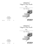
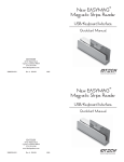
TM
OMNI
Slot Reader
TTL
User’s Manual
ID TECH
10721 Walker Street
Cypress, California 90630
(714) 761-6368
www.idtechproducts.com
80028503-005
Rev. D
R05/07
TM
OMNI
Slot Reader
TTL
User’s Manual
ID TECH
10721 Walker Street
Cypress, California 90630
(714) 761-6368
www.idtechproducts.com
80028503-005
Rev. D
R05/07
AGENCY APPROVED
Specifications for subpart B of part 15 of FCC rule for a Class A computing
device.
LIMITED WARRANTY
ID TECH warrants this product to be in good working order for a period of
one year from the date of purchase. If this product is not in good working
order as warranted above, or should this product fail to be in good working
order at any time during the warranty period, repair or replacement shall be
provided by ID TECH.
This warranty does not cover incidental or consequential damages incurred
by consumer misuse, or modification of said product. For limited warranty
service during the warranty period, please contact ID TECH to obtain an
RMA number and instructions for returning the product.
©2005 International Technologies & Systems Corporation. The information
contained herein is provided to the user as a convenience. While every effort
has been made to ensure accuracy, ID TECH is not responsible for damages
that might occur because of errors or omissions, including any loss of profit
or other commercial damage. The specifications described herein were current at the time of publication, but are subject to change at any time without
prior notice.
ID TECH is a registered trademark of International Technologies & Systems
Corporation. Omni and Value through Innovation are trademarks of International Technologies & Systems Corporation.
CLOCK: The CLOCK output is narrow pulse normally low, and goes high
when data is valid. The data level is stable at both the rising and falling edges
of the CLOCK pulse. CLOCK pulse width is typically 32 microseconds.
CARD PRESENT: The CARD PRESENT signal indicates data is being
read from the media being passed through the slot. It will not switch until
flux reversals (magnetic pulses) have been detected. After the flux reversals
have been detected, CARD PRESENT goes low. It stays low throughout the
reading process and for 5 to 10 milliseconds, after the last flux reversal is
read. Typically, CARD PRESENT is used to signal the start and finish of a
card read. It may also be used as an interrupt signal for alerting the firmware
that the reading operation is in process. This is an open drain output which
usually has an external pull-up resistor. If required, CARD PRESENT signals
from more than one read circuit may be tied together to provide a single
signal.
DATA: The DATA output level indicates the value of the bit being decoded
during a CLOCK pulse. It is a low level for ones (1) and a high level for
zeros (0). The DATA signal’s level is steady at the rising and falling edges
and during the low level of the CLOCK pulse.
BARCODE DATA SIGNAL: The Barcode Data Output is a single open
collector output that is normally at high impedance and at a high voltage
level based on the supply voltage to the external pull-up resistor. The output
is low to indicate a White area and high to indicate a Black area. The rising
and falling edges represent the contrast edges between White and Black as
the barcode is scanned. ID TECH supplies barcode decoder ASIC and
decoder electronics as separate product.
OPERATION
Make sure the Omni is properly cabled and is receiving sufficient power.
To read a card, slide the card, in either direction, through the slot, with the
magnetic stripe facing the magnetic head or the bar code facing the bar code
module, as appropriate.
1
AGENCY APPROVED
Specifications for subpart B of part 15 of FCC rule for a Class A computing
device.
LIMITED WARRANTY
ID TECH warrants this product to be in good working order for a period of
one year from the date of purchase. If this product is not in good working
order as warranted above, or should this product fail to be in good working
order at any time during the warranty period, repair or replacement shall be
provided by ID TECH.
This warranty does not cover incidental or consequential damages incurred
by consumer misuse, or modification of said product. For limited warranty
service during the warranty period, please contact ID TECH to obtain an
RMA number and instructions for returning the product.
©2005 International Technologies & Systems Corporation. The information
contained herein is provided to the user as a convenience. While every effort
has been made to ensure accuracy, ID TECH is not responsible for damages
that might occur because of errors or omissions, including any loss of profit
or other commercial damage. The specifications described herein were current at the time of publication, but are subject to change at any time without
prior notice.
ID TECH is a registered trademark of International Technologies & Systems
Corporation. Omni and Value through Innovation are trademarks of International Technologies & Systems Corporation.
6
CLOCK: The CLOCK output is narrow pulse normally low, and goes high
when data is valid. The data level is stable at both the rising and falling edges
of the CLOCK pulse. CLOCK pulse width is typically 32 microseconds.
CARD PRESENT: The CARD PRESENT signal indicates data is being
read from the media being passed through the slot. It will not switch until
flux reversals (magnetic pulses) have been detected. After the flux reversals
have been detected, CARD PRESENT goes low. It stays low throughout the
reading process and for 5 to 10 milliseconds, after the last flux reversal is
read. Typically, CARD PRESENT is used to signal the start and finish of a
card read. It may also be used as an interrupt signal for alerting the firmware
that the reading operation is in process. This is an open drain output which
usually has an external pull-up resistor. If required, CARD PRESENT signals
from more than one read circuit may be tied together to provide a single
signal.
DATA: The DATA output level indicates the value of the bit being decoded
during a CLOCK pulse. It is a low level for ones (1) and a high level for
zeros (0). The DATA signal’s level is steady at the rising and falling edges
and during the low level of the CLOCK pulse.
BARCODE DATA SIGNAL: The Barcode Data Output is a single open
collector output that is normally at high impedance and at a high voltage
level based on the supply voltage to the external pull-up resistor. The output
is low to indicate a White area and high to indicate a Black area. The rising
and falling edges represent the contrast edges between White and Black as
the barcode is scanned. ID TECH supplies barcode decoder ASIC and
decoder electronics as separate product.
OPERATION
Make sure the Omni is properly cabled and is receiving sufficient power.
To read a card, slide the card, in either direction, through the slot, with the
magnetic stripe facing the magnetic head or the bar code facing the bar code
module, as appropriate.
1
6
I/O for magnetic stripe only reader
with Tinned Wires
I/O for magnetic stripe & bar code
reader with Tinned Wires
COLOR
BROWN
YELLOW
ORANGE
BLUE
GREEN
GRAY
WHITE
RED
BLACK
COLOR
BROWN
YELLOW
ORANGE
BLUE
GREEN
GRAY
WHITE
PURPLE
DATA
RED
BLACK
SIGNAL
DATA 1
DATA 2
DATA 3
CLK 1
CLK 2
CLK 3
CARD PRESENT
+5 VDC
GROUND
I/O for bar code only reader with
Tinned Wires
COLOR
PURPLE
RED
BLACK
SIGNAL
DATA 1
DATA 2
DATA 3
CLK 1
CLK 2
CLK 3
CARD PRESENT
BAR CODE
+5 VDC
GROUND
SIGNAL
BAR CODE DATA
+5 VDC
GROUND
SPECIFICATIONS
Power Requirements,
Bar Code:
Power Requirements,
Magnetic:
Operating Current:
Operating
Temperature:
Power +5 VDC +/-10% (35mA maximum).
Ground 0 VDC (GND).
Power +5 VDC +/-10% (50mV ripple maximum).
Ground 0 VDC (GND). Chassis Ground connected
to GND and magnetic head case.
30mA maximum for bar code only. 5mA for magnetic stripe
only.
32° F to 131° F (0° C to 55° C).
Weatherproof Option:
-31° F to 140° F (-35° C to 60° C) without ice
build-up on magnetic head.
Storage Temperature:
-31° F to 140° F (-35° C to 60° C).
Relative Humidity:
Maximum 95% non-condensing.
Magnetic Head Life:
1,000,000 passes minimum.
Rail and Cover Life:
1,000,000 passes minimum.
Magnetic Read Rate:
Less than one error in 500,000 bits on cards
conforming to ISO 7811 1-5 (not induced by
operator error).
MAGSTRIPE DATA, CLOCK & CARD PRESENT
SIGNALS
Bar Code Source
Light:
Visible red 660 nm or Infrared 930 nm.
Minimum Bar Code
PCS:
60%.
The following is a timing diagram of typical DATA and CLOCK signals from
ID TECH electronics:
Bar Code Centerline:
.49 inches (12.50mm) from bottom of slot to center of
reading window.
Bar Code Resolution:
.006 inches (6 mil) minimum.
Magnetic Stripe
Formats:
ISO 7811, AAMVA, and CA DMV.
Swipe Speed:
Bar Code 5 to 65 inches per second, bi-directional.
Magnetic Stripe 3 to 60 inches per second,
bi-directional.
Card Width:
Bar code media .005 to .050 inches.
Magnetic stripe media .01 to .050 inches.
5
2
I/O for magnetic stripe only reader
with Tinned Wires
I/O for magnetic stripe & bar code
reader with Tinned Wires
COLOR
BROWN
YELLOW
ORANGE
BLUE
GREEN
GRAY
WHITE
RED
BLACK
COLOR
BROWN
YELLOW
ORANGE
BLUE
GREEN
GRAY
WHITE
PURPLE
DATA
RED
BLACK
SIGNAL
DATA 1
DATA 2
DATA 3
CLK 1
CLK 2
CLK 3
CARD PRESENT
+5 VDC
GROUND
I/O for bar code only reader with
Tinned Wires
COLOR
PURPLE
RED
BLACK
SIGNAL
DATA 1
DATA 2
DATA 3
CLK 1
CLK 2
CLK 3
CARD PRESENT
BAR CODE
+5 VDC
GROUND
SIGNAL
BAR CODE DATA
+5 VDC
GROUND
MAGSTRIPE DATA, CLOCK & CARD PRESENT
SIGNALS
The following is a timing diagram of typical DATA and CLOCK signals from
ID TECH electronics:
5
SPECIFICATIONS
Power Requirements,
Bar Code:
Power Requirements,
Magnetic:
Operating Current:
Operating
Temperature:
Power +5 VDC +/-10% (35mA maximum).
Ground 0 VDC (GND).
Power +5 VDC +/-10% (50mV ripple maximum).
Ground 0 VDC (GND). Chassis Ground connected
to GND and magnetic head case.
30mA maximum for bar code only. 5mA for magnetic stripe
only.
32° F to 131° F (0° C to 55° C).
Weatherproof Option:
-31° F to 140° F (-35° C to 60° C) without ice
build-up on magnetic head.
Storage Temperature:
-31° F to 140° F (-35° C to 60° C).
Relative Humidity:
Maximum 95% non-condensing.
Magnetic Head Life:
1,000,000 passes minimum.
Rail and Cover Life:
1,000,000 passes minimum.
Magnetic Read Rate:
Less than one error in 500,000 bits on cards
conforming to ISO 7811 1-5 (not induced by
operator error).
Bar Code Source
Light:
Visible red 660 nm or Infrared 930 nm.
Minimum Bar Code
PCS:
60%.
Bar Code Centerline:
.49 inches (12.50mm) from bottom of slot to center of
reading window.
Bar Code Resolution:
.006 inches (6 mil) minimum.
Magnetic Stripe
Formats:
ISO 7811, AAMVA, and CA DMV.
Swipe Speed:
Bar Code 5 to 65 inches per second, bi-directional.
Magnetic Stripe 3 to 60 inches per second,
bi-directional.
Card Width:
Bar code media .005 to .050 inches.
Magnetic stripe media .01 to .050 inches.
2
Slot Width:
.055 inches (1.37mm)
Dimensions:
Length: 5 inches (127mm).
Width: 2.05 inches (52mm).
Height:
1.38 inches (35mm).
Weight:
1 lb.
Cable Length:
2-foot unterminated cable.
DESCRIPTION
The rugged Omni™ slot reader can read bar codes, or 1, 2, or 3 tracks of
magnetic stripe information in heavy-use applications. The Omni has a metal
base and thick plastic housing. The metal base allows for mounting with
screws or Velcro fasteners. The single I/O cable provides the connections for
electrical power and decoded data signals. There are three options for the I/O
cable. If the I/O cable is terminated with a 9-pin connector, the Omni will be
either a magnetic stripe reader or a barcode reader (not both). If the I/O cable
is terminated with striped and tinned wires, the Omni can be a magnetic stripe
reader, a barcode reader, or able to read both technologies.
The electronics for magnetic stripe media are located on a single PCA
mounted below the 99mm rail assembly. TTL level signals (data and clock)
go directly out through an I/O cable. The electronics for bar code media are
located on a single PCA mounted to the bar code module. Again, TTL level
signals go directly out through an I/O cable.
The Omni reliably processes data encoded within ANSI and ISO standards,
on both high and low coercivity magnetic media. The circuit is designed
to read cards demagnetized down to 30% or 40% of ISO and ANSI signal
levels, on tracks 1/3 or 2 respectively. These reading characteristics are
designed to insure that the Omni will reliably read ‘real world’ cards.
In order to insure reliable reading under varying conditions, the Omni will
read magnetic media at speeds from 5 inches per second (IPS) to 55 IPS with
typical accelerations. The output signals consist of a DATA and CLOCK for
each encoded track. The electronics operate with 5VDC ± 10%.
A CARD PRESENT signal is provided to alert the host when magnetic media
is passed through the reader. It is activated after magnetic pulses
3
(10 for Track 2 or 24 for Tracks 1 and 3) have been detected and stays valid
until after the last pulse is read. Media may be read bi-directionally without
any pre-conditioning of the electronics, although the host system must
employ enough data storage to ensure it can properly store and utalize the
decoded bit sequence.
I/O CABLE CONNECTIONS (9-PIN)
The undecoded Omni reader can be connected to a decoder box using a 9-pin
squeeze-to-release connector. Pinout designations for bar code and magnetic
versions are as follow:
MAGNETIC
PIN
COLOR
SIGNAL
1
2
3
4
5
6
7
8
9
BLUE
BROWN
GRAY
YELLOW
GREEN
ORANGE
BLACK
WHITE
RED
CLK1
DATA1
CLK3
DATA2
CLK2
DATA3
GND
CARD PRESENT
VCC
PIN
COLOR
SIGNAL
1
2
3
4
5
6
7
8
9
——BROWN
————————BLACK
——RED
——DATA*
————————GND
——VCC
BAR CODE
*Host needs to provide 8.2K pull-up resistor (for TTL barcode only).
4
(10 for Track 2 or 24 for Tracks 1 and 3) have been detected and stays valid
until after the last pulse is read. Media may be read bi-directionally without
any pre-conditioning of the electronics, although the host system must
employ enough data storage to ensure it can properly store and utalize the
decoded bit sequence.
HOST CONNECTIONS
The undecoded Omni reader is connected to a decoder box using a 9-pin
squeeze-to-release connector. Pinout designations for both bar code and
magnetic versions are as follow:
MAGNETIC
PIN
COLOR
SIGNAL
1
2
3
4
5
6
7
8
9
BLUE
BROWN
GRAY
YELLOW
GREEN
ORANGE
BLACK
WHITE
RED
CLK1
DATA1
CLK3
DATA2
CLK2
DATA3
GND
CARD PRESENT
VCC
PIN
COLOR
SIGNAL
1
2
3
4
5
6
7
8
9
——BROWN
————————BLACK
——RED
——DATA
————————GND
——VCC
BAR CODE
*Host needs to provide 8.2K pull-up resistor (for TTL barcode only).
4