1
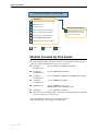
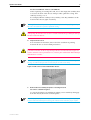
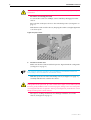
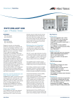
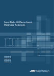
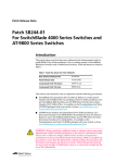
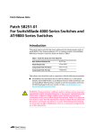
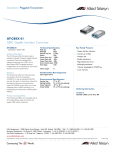
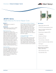
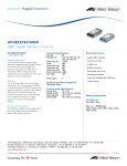
SwitchBlade Line Card
Quick Install Guide
SwitchBlade Line Card Quick Install Guide
Document Number C613-04030-01 REV H.
Copyright © 2002, 2006 Allied Telesyn International, Corp. 19800 North Creek Parkway,
Suite 200, Bothell, WA 98011, USA.
All rights reserved. No part of this publication may be reproduced without prior written
permission from Allied Telesyn.
Allied Telesyn International, Corp. reserves the right to make changes in specifications
and other information contained in this document without prior written notice. The
information provided herein is subject to change without notice. In no event shall Allied
Telesyn be liable for any incidental, special, indirect, or consequential damages
whatsoever, including but not limited to lost profits, arising out of or related to this
manual or the information contained herein, even if Allied Telesyn has been advised of,
known, or should have known, the possibility of such damages.
All trademarks are the property of their respective owners.
Quick Install Guide
3
Documentation Roadmap
SwitchBlade
Safety and Statutory Information Booklet
Hardware Reference
Software Reference
General Customer Support
Chassis & Fan Tray Quick Install Guide
Visit www.alliedtelesyn.co.nz for
the latest documentation, FAQs,
and support information.
Power Supply Unit Quick Install Guide
Switch Controller Quick Install Guide
Line Card Quick Install Guide
Bandwidth Expander Quick Install Guide
Printed
Acrobat PDF
Website
Models Covered By This Guide
This Quick Install Guide includes information on installing the following line
cards. The suffix V2 indicates the silicon revision level:
■
AT-SB4311
AT-SB4311 V2
48-port 10BASE-T/100BASE-TX (RJ-45)
■
AT-SB4352
AT-SB4352 V2
32-port 100BASE-FX (MT-RJ)
■
AT-SB4412
AT-SB4412 V2
24-port 10BASE-T/100BASE-TX/1000BASE-T (RJ-45)
■
AT-SB4441
AT-SB4441 V2
■
AT-SB4442 V2
■
AT-SB4541
■
Information on installing switch controllers can be found in the SwitchBlade
Switch Controller Quick Install Guide.
8-port 1000BASE-X (GBIC)
24-port 1000BASE-T copper or
1000 BASE (SX,LX or ZX) fibre (SFP)
1-port 10GBASE-LR (XFP)
Quick Install Guide updates can be downloaded from
www.alliedtelesyn.co.nz/support/switchblade/.
C613-04030-01 REV H
4
SwitchBlade Line Card
Package Contents
The following items are included with each line card. Contact your sales
representative if any items are damaged or missing.
■
One SwitchBlade line card.
■
One SwitchBlade Line Card Quick Install Guide.
■
One Safety and Statutory Information booklet.
■
One warranty card.
Related items that can be purchased separately:
■
Blank faceplates for switch controller and line card bays (AT-SB4193).
■
Approved pluggable transceivers (GBICs, SFPs and XFPs). Contact your
authorised Allied Telesyn distributor or reseller for more information.
Installing a Line Card
Line cards can be hot swapped. There is no need to power down the switch when
installing or removing line cards. See the SwitchBlade Hardware Reference for detailed
information on the operational characteristics of hot swapped interfaces.
Follow these steps to install a line card:
1.
Read the safety information
The SwitchBlade Safety and Statutory Information booklet includes all
relevant safety information. A copy of this booklet is supplied with each
line card. A PDF version can be found on the CD-ROM that ships with
every switch controller and every chassis, or can be downloaded from
www.alliedtelesyn.co.nz/support/switchblade/.
2.
Gather the tools and equipment you will need
To loosen or secure the line card’s mounting screws you will need a
Phillips #2 screwdriver.
3.
Choose a bay for the line card
For the SwitchBlade 8 chassis (AT-SB4108):
Unless replacing an existing line card, choose the empty line card bay that
is closest to the chassis’ centre. This provides optimum cooling. Line card
bays are bays 1 to 8.
For example, fill line card bays 4 and 5 first, followed by bays 3 and 6, then
bays 2 and 7, and lastly bays 1 and 8. Bay numbers can be found on the
chassis, above each bay.
C613-04030-01 REV H
Quick Install Guide
5
For the SwitchBlade 4 chassis (AT-SB4104):
Unless replacing an existing line card, choose the empty line card bay that
is closest to bottom of the chassis. This provides optimum cooling. Line
card bays are bays 1 to 4.
For example, fill line card bay 4 first, and bay 1 last. Bay numbers can be
found on the chassis, right of each bay.
Although line cards will operate in any combination of line card bays, filling the bays in
the order described above provides optimum cooling.
Do not attempt to install a line card in a switch controller bay (bay A or B).
Attempting to install a line card in a switch controller bay is likely to damage
the line card and chassis.
4.
Prepare the line card
In an antistatic environment, remove the line card from its packing
material. Be sure to observe ESD precautions.
Do not attempt to install a line card without observing correct antistatic
procedures. Failure to do so may damage the line card and chassis. If you are
unsure what the correct procedures are, contact your authorised Allied Telesyn
distributor or reseller.
An ESD socket is provided on the front panel of the SwitchBlade chassis (see Figure 1
on page -5). This socket provides a connection for an ESD wrist strap.
Figure 1: ESD socket on the SwitchBlade 8 chassis.
5.
Remove the line card bay faceplate or existing line card
To remove a blank faceplate:
Loosen the faceplate’s two Phillips mounting screws until they disengage
from the chassis, then remove the faceplate.
Keep the faceplate for future use. If you should remove a line card, replace the faceplate
to prevent dust and debris from entering the chassis and to maintain proper airflow.
C613-04030-01 REV H
6
SwitchBlade Line Card
The switch may overheat or be damaged by dust and debris if bays are left
uncovered.
To remove an existing line card:
Loosen the line card’s two Phillips screws until they disengage from the
chassis.
Move the line card ejector levers to the unlocked position (see Figure 2 on
page -6).
Slide the line card out of the chassis, keeping the card in a straight alignment
so it doesn’t jam.
Figure 2: Ejector levers.
6.
Insert the new line card
Make sure the line card’s metal back-panel is aligned with the card guides
(see Figure 3 on page -7).
Line cards are mounted vertically in the SwitchBlade 8 (AT-SB4108) chassis and
horizontally in the SwitchBlade 4 (AT-SB4104) chassis.
With the ejector levers in the unlocked position (see Figure 2 on page -6),
carefully slide the line card into the chassis.
When inserting a line card, take care to slide the card’s metal back-panel along
both guides at an equal rate. If a line card becomes tight, it must not be forced.
Instead, gently withdraw the card and try again, taking extra care to keep the
card aligned with the card guides. Forcing a misaligned or jammed line card is
likely to damage the card or chassis.
The ejectors’ locking mechanisms should align with their slots in the
chassis (see Figure 4 on page -7).
C613-04030-01 REV H
Quick Install Guide
7
Figure 3: Card guides on the SwitchBlade 8 chassis.
bottom card guide
Figure 4: Ejector lever and locking slot.
Extractor lever
7.
Secure the line card
Move the ejector levers to the locked position and tighten the line card’s
two Phillips screws (see Figure 2 on page -6).
If the chassis is receiving power, one or more L/A LEDs will light amber
when the line card is correctly installed. The LED(s) will remain lit until the
card is configured.
8.
For cards that accept miniature pluggable transceivers, such as GBICs, SFPs and
XFPs, install the transceivers.
Slide each transceiver into its appropriate slot and press it firmly into
place.
A range of pluggable transceivers have been tested and approved for use with the
SwitchBlade. Contact your authorised Allied Telesyn distributor or reseller for more
information, or visit www.alliedtelesyn.co.nz.
In order to connect each fibre into its correct terminal, check which terminal is the
“Send” and which is the “Receive” by reading the marking on each GBIC before
inserting it into its card socket.
9.
Connect the data cables
Make sure each cable connection is secure.
C613-04030-01 REV H
8
SwitchBlade Line Card
Line Card LEDs
The following LEDs will operate if the line card is installed in conjunction with
a properly configured switch controller, at least one functional PSU, and a fan
tray.
Table 1: LEDs on the 4412 24-port 10/100/1000BASE (RJ-45) Line Card .
LED
State
Function
L/A
Green
A 1000 Mbps link is open.
Flashing green
1000 Mbps activity is occurring.
Amber
A 10/100 Mbps auto-negotiating link is open.
The L/A LED for port 1 briefly lights at switch
power up, or when the card is hot swapped.
Flashing amber
10 or 100 Mbps activity is occurring.
Green
The port is operating in full-duplex mode.
Amber
The port is operating in half-duplex mode.
Flashing amber
Collisions are occurring.
(Link activity)
D/C
(Duplex/Collision)
For the AT-SB4311 48-port line card, one LED is provided for each port. The
default is for the LED to show link activity (L/A). To see Duplex/Collision
activity (D/C), press and hold the LED Mode button located on the line card’s
front panel
Table 2: LEDs on the AT-SB4352 32-port 100BASE-FX (MT-RJ) Line Card.
LED
State
Function
L/A
Green
A 100 Mbps link is open.
Flashing Green
100 Mbps activity is occurring.
Amber
The L/A LEDs for ports 1 and 17 briefly light at
switch power up or when the card is hot
swapped.
Green
The port is operating in full-duplex mode.
Amber
The port is operating in half-duplex mode.
Flashing Amber
Collisions are occurring.
(Link/Activity)
D/C
(Duplex/Collision)
C613-04030-01 REV H
Quick Install Guide
9
Table 3: LEDs on the AT-SB4441 8-port 1000BASE GBIC Line Card.
LED
State
Function
L/A
Green
A link is open.
Flashing Green
Activity is occurring.
Amber
The port is operating in half-duplex mode. The
L/A LED for port 1 briefly lights at switch
power-up or when the card is hot swapped.
Flashing Amber
Half-duplex activity is occurring.
Off
No link is present.
Green
A GBIC is installed and enabled.
Amber
A GBIC is installed but disabled.
Flashing Amber
A fault is occurring on the link.
Off
No GBIC is installed.
(Link/Activity)
GBIC Status
Table 4: LEDs on the AT-SB4442 V2 24-Port (SFP) Gigabit Line Card.
LED
State
Function
SFP
Steady Green
Glow
For fibre SFPs:
The SFP is able to send and receive a light
signal.
(Link/Activity)
For copper SFPs:
Communication at 1 Gbps has been
established.
Flashing Green
Data activity is taking place.
Steady Amber
Glow
The SFP has been inserted.
Flashing Amber
The SFP is not functioning correctly.
Off
No link is present.
Table 5: LEDs on the AT-SB4541 1-port (XFP) 10GBASE-R Line Card.
LED
State
Function
L/A
Green
Communication has been established.
Flashing Green
10GE activity is occurring
Off
No link is present
Green
An XFP is installed and enabled
Amber
An XFP is installed, but disabled.
Flashing Amber
An XFP is not ready, or faulty.
Off
No XFP is installed
(Link/Activity)
XFP
C613-04030-01 REV H
10
SwitchBlade Line Card
More troubleshooting information can be found in the SwitchBlade Hardware
Reference.
Where To Find More Information
Sources of further information:
■
A Documentation and Tools CD-ROM is included with every switch
controller or chassis supplied. This contains the complete documentation
set for your switch and its expansion options, as well as tools for managing
the switch.
■
The SwitchBlade Safety and Statutory Information booklet, which provides
safety and statutory information for the SwitchBlade and its accessories.
■
The SwitchBlade Hardware Reference, which provides detailed information
on the switch and its hardware features.
■
The SwitchBlade Software Reference, which provides detailed information on
configuring the switch and its software.
■
The SwitchBlade Power Supply Unit Quick Install Guide, which outlines the
procedure for installing AC and DC power supply units.
■
The SwitchBlade Switch Controller Quick Install Guide, which outlines the
procedure for installing switch controllers.
■
The SwitchBlade Chassis and Fan Tray Quick Install Guide, which outlines the
procedure for installing the chassis and its fan tray.
■
The SwitchBlade Bandwidth Expander Quick Install Guide, which outlines the
procedure for installing bandwidth expanders.
■
www.alliedtelesyn.co.nz/support/switchblade/
C613-04030-01 REV H