1
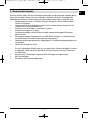
GigaSystem_17_8_deu_engl_23112011_3.qxp
28.11.2011
09:34
Seite 1
Montageanleitung
Installation instructions
TechniSat
GigaSystem 17/8G, 17/8K
www.technisat.de
www.technisat.com
GigaSystem_17_8_deu_engl_23112011_3.qxp
28.11.2011
09:34
Seite 2
D
Inhalt
1
2
3
4
4.1
4.2
4.3
5
5.1
5.2
5.3
5.4
5.5
5.6
6
7
8
Ve r we n du ng s z we ck
Si ch e rh eit s h inwe is e
G e r ä t e d es G iga S y s t e m 17 /8
M o n t a ge in E in- od er Z we ifa milie n h ä u se r n
Wa h l d e r Au ße ne inh eit / L N B
K a b e l u nd S te cke r
Wa h l d e r Ant e nn en s te ckd ose n
Er r i ch tu ng von g r o ße n G iga Syst e m-An la g e n .
We i t er ge he nd e H inwe is e z u L NB’s, Ka b e ln , Do se n u sw.
Pl a n un g
In s t a l latio n
Ei n m e s s e n
Ko m b i nat io ns m ög lich ke ite n
Sch a ltm ög lich ke ite n m it un d o h n e DiS E q C
A n l a gen be is pie le
Fe h l e r s uch hilfen
Te ch nis ch e Date n
1 Verwendungszweck
Die Geräte des GigaSystem 17/X dienen zur Versorgung von vielen Teilnehmern mit bis zu
16 Sat-ZF-Ebenen und dem terrestrischen Signal.
So können zum Beispiel:
>
>
Die Vollbänder von 4 Satelliten (digitale und analoge Programme)
oder
gezielt ausgesucht 16 verschiedene Sat-ZF-Ebenen verteilt werden.
Für Hausbewohner, die fremdsprachige Sender nicht interessieren, kann das GigaSystem
17/X kosteneffizient unter bestimmten Bedingungen auch mit anderen TechniSatMultischaltersystemen kombiniert werden, siehe Abschnitt 5.5.
Die Verstärkungen der Geräte sind praxisgerecht und engtoleriert. Im Satellitenbereich
haben die Abzweige eine schräglagenentzerrte Übertragungscharakteristik mit Verstärkung
am oberen Bandende.
Die schräglagenentzerrte aktive Terrestrik ist zukunftssicher für die Verteilung von DVB-T
auch in Senderrandgebieten geeignet. Wenn gefordert, kann stattdessen auch DVB-C eingespeist werden, eine CENELEC-konforme Belegung des terrestrischen Frequenzbereiches
mit 42 Kanälen ist möglich.
2
GigaSystem_17_8_deu_engl_23112011_3.qxp
28.11.2011
09:34
Seite 3
D
2 Sicherheitshinweise
Zu Ihrem Schutz sollten Sie die Sicherheitsvorkehrungen vor der Montage sorgfältig durchlesen. Der Hersteller übernimmt keine Haftung für Schäden, die durch unsachgemäße
Handhabung und durch Nichteinhaltung der Sicherheitsvorkehrungen entstanden sind.
>
Die Komponenten sind in trockenen Räumen auf ebener, schwer entflammbarer
Fläche zu montieren.
>
Lüftungsschlitze der Komponenten dürfen nicht verdeckt werden. Bauen Sie die
Geräte nicht in die Dachisolation ein.
>
Installieren Sie die Anlage im stromlosen Zustand.
>
Die Antennenanlage ist zu erden.
>
Die Antennenanlage muß den Bestimmungen entsprechend gegen Blitzschlag
geschützt sein.
>
Die entsprechenden Europanormen und VDE-Bestimmungen zur Gewährleistung
der elektrischen Sicherheit müssen berücksichtigt werden.
>
Nationale genehmigungsrechtliche Regelungen für Rundfunkempfangsanlagen sind
zu beachten.
>
Öffnen Sie niemals das Gerät.
>
>
>
Ein evtl. notwendiger Eingriff sollte nur von geschultem Personal ausgeführt werden.
In folgenden Fällen sollten Sie das Gerät vom Netz trennen und einen Fachmann
um Hilfe bitten:
das Gerät war Feuchtigkeit ausgesetzt bzw. Flüssigkeit ist eingedrungen,
bei Fehlfunktionen,
bei starken äußeren Beschädigungen.
3
GigaSystem_17_8_deu_engl_23112011_3.qxp
28.11.2011
09:34
Seite 4
D
3 Geräte des GigaSystem 17/X
GigaSystem 17/8 G (Art.-Nr. 0000/3271)
Dieser Multischalter ist das Grundgerät der Verteilung. Er schaltet die Signale von bis zu 16
Satelliten-ZF-Ebenen an bis zu 8 Teilnehmer. Die Ausgänge sind schräglagenentzerrt. Das
Gerät besitzt ein kräftiges Netzteil.
Das Gerät GigaSystem 17/8 G stellt zur eventuellen Weiterverwendung eines vorhandenen
Schalt-LNB’s an den Eingängen Option A / Pos. A / High-Band immer das 22kHzSteuersignal zur Verfügung. Außerdem besitzt es eine (abschaltbare) Stromsparschaltung.
GigaSystem 17/8 K (Art.-Nr. 0000/3272)
Diese Kaskadiermatrix für 8 Teilnehmer kann bei Verwendung von Zwischenverstärkern bis
zu viermal hintereinandergeschaltet werden. Die Stromversorgung erfolgt vom GigaSystem
17/8 G und wird ohne interne Querverbindung an allen Stammleitungen des 17/8K durchgereicht.
Zur Errichtung von größeren Anlagen wird nachstehendes Zubehör angeboten, welches in den Montageanleitungen der einzelnen Geräte detailliert
beschrieben ist.
4
28.11.2011
09:34
Seite 5
Aktiver Abzweiger 17/2A (Art.-Nr. 0000/3270)
Diese Baugruppe ermöglicht es, die Signale eines Verteilstammes vielfach, pro Gerät jeweils
doppelt, abzuzweigen und nachgeschalteten Unterverteilungen zuzuführen. Die
Stammleitungen sind gleichstromdurchlässig und fast dämpfungslos, die Abzweige sind
schräglagenentzerrt verstärkt. Der 17/2A ist bis zu sechsfach kaskadierbar, um Signale für
die Unterverteilungen der Etagen eines Hochhauses oder für Häuser einer Häuserzeile
bereitzustellen.
Das Gerät wird selbst über die Unterstämme 1 gespeist, speist aber die Stämme nicht von
dort. Am Stammausgang des letzten 17/2A muss, um Schaltmatrizen, Verstärker und LNB’s
im Stamm zu speisen, immer ein 17/8G angeschlossen sein.
Zwischenverstärker 17Z (Art.-Nr. 0000/3269)
Die Verstärkungen und die festeingestellte Schräglagenentzerrung des Gerätes sind für den
Ausgleich der Dämpfung durch Kabel und/oder Komponenten von 13dB bei 2150MHz ausgelegt. Die Verstärkung des terrestrischen Pfades ist einstellbar.
Im Zwischenverstärker sind gleichstrommäßig jeweils alle horizontalen und vertikalen
Stämme miteinander verbunden (außer SAT1, High-Band). Damit wird der
Gleichstromwiderstand einzelner Leitungen in großen Anlagen stark herabgesetzt.
5
D
GigaSystem_17_8_deu_engl_23112011_3.qxp
GigaSystem_17_8_deu_engl_23112011_3.qxp
28.11.2011
09:34
Seite 6
D
Passiver Verteiler 17P (Art.-Nr. 0000/3268)
Mit einer Dämpfung von maximal 4dB erfolgt hiermit eine Leistungsteilung der Signale aller
Satelliten-ZF-Ebenen und der Terrestrik auf zwei Ausgänge. Um eine gegenseitige
Beeinflussung der speisenden Netzteile zu verhindern, ist der obere Ausgang gleichspannungsentkoppelt.
4 Montage in Ein- oder Zweifamilienhäusern
Die Montage von kleinen Anlagen ist problemlos und kann vom Laien durchgeführt werden,
ein Beispiel ist im Abschnitt 6.1 aufgezeigt.
>
>
>
>
>
>
>
>
>
>
>
Wählen Sie die Durchmesser der Spiegel so aus, dass die Eingangssignale ungefähr
die gleiche Größe haben. Lassen Sie sich vom Fachhändler beraten.
Eine Sternverteilung vom Dachboden oder aus der Hausmitte heraus wird empfohlen.
Ohne zusätzliche Verstärkung kann die Kabellänge vom LNB bis zur
Antennensteckdose maximal 70m sein, hierbei CoaxSat 2150 zur Dose verwenden.
Bei Verwendung von mehreren Schaltmatrizen hat sich die verteilte (etagenweise)
Kaskadierung als zweckmäßig erwiesen.
Da Kabel sehr empfindlich sind, sollten Sie diese erst spät im Bauablauf verlegen.
Verwenden Sie zur Installation, wenn möglich, Leerrohre. Knicken Sie die Kabel nicht.
Wenden Sie keine starken Zugbelastungen an.
Installieren Sie die Anlage im stromlosen Zustand.
Eine Überprüfung der Kabel auf Kurzschluss vor dem Kontaktieren vermeidet besonders bei größeren Anlagen eine spätere zeitraubende Fehlersuche.
Achten Sie darauf, dass die Leitungen von den LNB’s nicht untereinander vertauscht
werden. Zur Erleichterung verwenden Sie am besten Mehrfachkoaxialkabel mit
Nummerierung der einzelnen Kabel und kennzeichnen Sie die entsprechenden
Mehrfachkabel mit Hilfe eines geeigneten Stiftes.
Nicht benutzte Eingänge dürfen nicht mit einem Abschlusswiderstand beschaltet werden.
Falls Sie ein Schalt-LNB weiterverwenden, achten Sie bei langen Zuleitungen bitte
darauf, dass die Schaltspannungen am LNB noch ausreichend sind (größer als 16,5V
für die horizontalen Ebenen.; größer als 11,5V für die vertikalen Ebenen)
Die Stromsparschaltung des 17/8G kann nur dann eingeschaltet werden, wenn Sie
keine Kaskadiermatrix davor installiert haben.
Es ist kein terrestrischer Vorverstärker notwendig.
4.1 Wahl der Außeneinheit / LNB’s
In der Regel verwendet man vier Quatro-LNB’s.
Wenn Sie vorhandene LNB’s verwenden möchten oder eine spezielle Kombination von
Polarisationsebenen übertragen wollen, lesen sie bitte im Abschnitt 5.1 nach.
6
GigaSystem_17_8_deu_engl_23112011_3.qxp
28.11.2011
09:34
Seite 7
>
>
>
>
>
D
4.2 Kabel und Stecker
Für die Verbindung der LNB’s mit dem Multischalter bzw. der Komponenten untereinander empfehlen wir die Verwendung von Mehrfachkoaxialkabel, 4 oder 5 Kabel in
einem Mantel, z.B. MULTYMEDIA-Kabel (Art.-Nr 0001/3014).
Zur Verbindung des Multischalters mit den Antennensteckdosen eignet sich am
besten Mini-Koaxkabel (Art.-Nr 0001/3011).
Aufgrund der Verstärkung der Geräte können Sie auch solch ein dünnes, leicht handhabbares Kabel ( mit etwas mehr Dämpfung ) einsetzen.
Um lange Kabelverbindungen (LNB – Dose nahe 70m) zu den Antennensteckdosen
herzustellen, verwenden Sie bitte das dämpfungsarme Koaxialkabel CoaxSat 2150
(Art.-Nr 0002/3107) oder (Art.-Nr 0001/3106).
TechniSat empfiehlt, für professionelle Installationen keine F-Stecker zu verwenden,
die auf das Kabel aufgeschraubt werden. Für den Heimgebrauch, wo selten spezielle
Konfektionierungswerkzeuge zur Verfügung stehen, sind sie anzuraten. Kaufen Sie
möglichst solche mit Kabelmantel-Überwurfmutter.
Kaufen Sie Kabel und Stecker bei Ihrem Fachhändler. Hier erhalten Sie Meterware an
Kabeln und die entsprechende Beratung! Abisolierlängen siehe Abschnitt 5.1.
4.3 Antennensteckdosen
Die Teilnehmer werden über Antennensteckdosen TechniPro SV 500 (3-Loch, Art.-Nr
0000/3075) angeschlossen. So lassen sich ohne Umstecken auch die terrestrischen
Programme empfangen, außerdem sind damit die angeschlossenen Geräte vor bandfremden Störungen geschützt.
5 Errichtung von großen GigaSystem-Anlagen
Verteilanlagen für Satelliten- und Breitbandkabel- (bzw. terrestrische) Signale mit mehr als
24 Anschlussstellen sollten nur von Fachleuten installiert werden, die über das Wissen um
die Zusammenhänge und ein selektives Antennenmessgerät verfügen.
Große Anlagen werden in einer Mehrfach-Baum-Sternstruktur aufgebaut.
Von einem Hauptstamm kann eine Vielzahl von Unterverteilungen abgegriffen werden. Nur
so ist gewährleistet, dass die Isolation nicht bis zur Untauglichkeitsgrenze (20dB, incl.
Frequenzgangs- und Nachbarreserven) verschlechtert wird.
Zum besseren Verständnis hier einige kurze Funktionshinweise:
In den Schaltmatrizen wird das Signal über Richtkoppler abgegriffen und dann mit MMICSchaltern über Filter und Verstärker an die Teilnehmer weitergeleitet.
Obwohl über diesen Pfad die Schaltmatrizen insgesamt dämpfungslos arbeiten, ist der
Pegel in der Schaltmatrix jedoch stellenweise erheblich tiefer, der Eingangspegel der
Schaltmatrix darf deshalb 58dBμV nicht unterschreiten.
Dank der hohen Entkopplung der Stammleitungen sind, bei halbwegs gleich-pegeliger
Einspeisung und Beachtung der Hinweise dieses Abschnittes, Störquellen durch mangelnde
Isolation praktisch ausgeschlossen.
7
GigaSystem_17_8_deu_engl_23112011_3.qxp
28.11.2011
09:34
Seite 8
D
5.1 Weitergehende Hinweise zu LNB’s, Kabeln und Dosen
LNB’s:
Schalt-LNB’s (Quatro-Switch-LNB oder Twin-LNB’s) sollten grundsätzlich nur eingesetzt
werden, wenn sie schon vorhanden sind, sowie nur bei Einzelanlagen und auch nur bei
den SAT1-Eingängen (Option A / Position A, hier liefert die Schaltmatrix 22 kHz für das
High-Band). Die Verschlechterung der Isolation durch Schalt-LNB’s wirkt sich bei
Einzelanlagen (z.B. ein 17/8G und ein 17/8K) nicht aus.
Bei SAT1 können zwei Twin-LNB’s natürlich nur für zwei verschiedene Himmelspositionen
verwendet werden.
Sofern nur zwei Ebenen eines Low-Bandes einer Sat-Position empfangen werden sollen,
kann dafür auch ein Dual-Output-LNB oder ein TWIN-LNB verwendet werden.
Falls von einer bestimmten Himmelspositionen nur eine Polarisationsebene im Low-Band
gebraucht wird, kann dafür auch ein Single-LNB verwendet werden. Eine
Polarisationsebene im High-Band kann mit einem Single-LNB nur bei SAT1 empfangen
werden.
Kabel:
Tabelle 1:
Dämpfung (dB / x Meter) einsetzbarer Kabeltypen
Typ
>
Mini-,
Multimediakabel
CoaxSat 2150 (100 dB)
dB bei Frequenz/MHz
30 300 860 2150
30
300
860
2150
10 m
20 m
30 m
40 m
50 m
60 m
70 m
Loop-Widerstand
(Seele und Schirm)
- für ein Kabel
- der Kabel einer
Speisespannung
0,3
0,6
0,9
1,2
1,5
1,8
2,1
0,5
1
1,5
2
2,5
1,5
3
4,5
6
7,5
2,5
5
7,5
10
12,5
4,2
8,4
12,6
16,8
21
1
2
3
4
5
6
7
1,8
3,6
5,4
7,2
9,0
10,8
12,6
0.35 Ohm/10m
60 mOhm/10m
3
6
9
12
15
18
21
0.56 Ohm/10m
80 mOhm/10m
Zur Auswahl der Kabel siehe auch Abschnitt 4.2.
8
28.11.2011
09:34
Seite 9
D
GigaSystem_17_8_deu_engl_23112011_3.qxp
Antennensteckdosen:
Tabelle 2:
Pegel am Ausgang einer SV 500-Antennensteckdose
Dämpfung der Dose
minimal
Pegel
empfohlen maximal
Sat-Bereich
2 dB
47 dBμV
58 dBμV
79 dBμV
UKW
5 dB
50 dBμV
63 dBμV
70 dBμV
analoges terr. TV
55 dBμV
63 dBμV
70 dBμV
DVB-T
DVB-C
40 dBμV
50 dBμV
55 dBμV
70 dBμV
70 dBμV
VHF 4 dB/ UHF 3 dB
47 dBμV
Die TechniPro SV 500 bietet den Rückwegzugang an der TV-Buchse (VHF/UHF). Um TV
und Vor/Rückweg getrennt zur Verfügung zu haben, müsste nach der SV500 ein BK 2Wege-Verteiler (Art.-Nr. 0000/3068) gesetzt werden. Zu beachten ist in diesem Fall die
Gesamtdämpfung von ca. 8dB.
Tabelle 3:
Pegel am Ausgang einer SVR 500-Antennensteckdose
Dämpfung der Dose
minimal
Sat-Bereich
2 dB
UKW
4 dB
analoges terr. TV
5 dB
Rückweg
4 dB
Pegel
empfohlen maximal
siehe Tabelle 2
100 dBμV 110 dBμV
9
117 dBμV
GigaSystem_17_8_deu_engl_23112011_3.qxp
28.11.2011
09:34
Seite 10
Unterputz-Verteilschrank:
D
Für die Installation im Treppenhaus, am besten für eine Sternverteilung aus der Hausmitte
heraus, bietet sich ein Unterputz-Verteilschrank an. In einem sochen Verteiler kann bei
Bedarf auch ein Zwischenverstärker oder ein Verteiler mit Platz finden.
Der Schrank sollte mit einem Schloss versehen sein.
5.2 Planung
Für große Verteilanlagen ist eine Reichweitenrechnung und damit die Betrachtung folgender
Punkte unbedingt notwendig:
1.
2.
3.
4.
Pegel
Isolation
Spannungsabfälle
Strombelastung der Netzteile
Satellitenbereich
>
>
>
>
>
>
>
>
>
>
>
>
Stellen Sie einen Bauplan mit Angabe aller Kabellängen auf.
Die Schaltmatrizen sind näherungsweise dämpfungslos, arbeiten Sie nicht mit zu
hohen Pegeln auf den Stammleitungen, bei Sat empfehlen wir 75dBμV.
Tragen Sie die vorhandenen und benötigten Pegel an den Ein- und Ausgängen der
Komponenten ein, siehe Technische Daten und Tabelle 1 (Kabeldämpfungen).
Achtung: Besonders bei einer großen Sat-Verteilung addieren sich kleine
Nachlässigkeiten zu einem erheblichen Gesamtfehler.
Vermeiden Sie Übersteuerungen sowie ein Absinken unter den Minimalpegel der
Dose, siehe Tabelle 2. Eine Mindest-BER (Bit-Error-Rate, Bitfehlerrate, bei DVB)
bzw. das notwendige C/N-Verhältnis (Träger-Rausch-Verhältnis, beim analogen FMTV) muss an jeder Stelle gewährleistet sein.
Eingangssignalbereich des Receivers (Regelbereich): ca. 44dBμV...84dBμV
Stellen Sie die Verstärkung und den Einsatz der Kabel so ein, dass die
Transponderpegel am oberen Bandende wegen fallenden Frequenzgang der LNB´s
und praktisch nicht vorständig realisierbarer Entzerrung der Kabel nicht kleiner als
die minimalen Werte werden. In der Praxis treten hier (leider) in großen Anlagen bis
zu 10 dB Abfall verglichen mit der Bandmitte auf.
Überschlagen Sie, ob die Isolation ausreicht. Jede weitere in Serie geschaltete
Baugruppe gleicher Isolation verschlechtert um ca. 4dB. Schlechter als 20dB sollte
die Isolation beim Teilnehmer nicht sein.
Schätzen Sie die Wirkung der Spannungsabfälle über den einzelnen Geräten ab. Die
Spannung für die LNB’s und die Zubehörteile muss noch reichen (hor. >16,5V, vert.
>11.5V).
Überprüfen Sie auch die Strombelastung der einzelnen Netzteile. Die
Stromverbrauchswerte finden Sie in den technischen Daten.
Eine Planung mit Reserven dankt die Anlage mit zuverlässiger Funktion über Jahre
hinweg.
Falls auch der Rückweg benutzt wird, müssen die Signale der einzelnen Teilnehmer
(mit einer Reserve von 5dB) im Eingangssignalbereich des Headendtuners (i.d.R.
40...84dBμV) liegen.
10
GigaSystem_17_8_deu_engl_23112011_3.qxp
28.11.2011
09:34
Seite 11
>
>
Am einfachsten ist die Verwendung einer terrestrischen Breitbandantenne.
Achten Sie in diesem Fall besonders darauf, dass UKW-Signale nicht zu groß sind.
Wenn die Signale der einzelnen Bänder aus verschiedenen Richtungen kommen,
sind mehrere Antennen, zusammengeführt mit einem terrestrischen Combiner
(Filter), zu empfehlen. Unterschiedliche Pegel können (in Grenzen) mit den
Antennengrößen ausgeglichen werden.
Der Signalweg ist verhältnismäßig übersteuerungsfest ausgelegt (Ausgangspegel bei 60 dB
IMA3: 102 dBμV, nach DIN 45004 B). Jedoch sollten bei gleichzeitiger Verteilung von UKW,
VHF bzw. Kabelsignal sowie UHF bei auftretenden Kreuzmodulationsstörungen (Moiré) folgende Hinweise beachtet werden:
>
Setzen Sie bei schwachen Eingangssignalen nur dann einen (natürlich rauscharmen
und übersteuerungsfesten) Vorverstärker ein, wenn keine hochpegeligen Signale
dabei sind.
>
Analoge TV-Signale < 60 dBμV werden besonders bei größeren Anlagen zu stark
verrauscht und gestört, sie sind für eine Verteilung nicht geeignet.
45 dBμV-DVB-T-Eingangssignale können noch verteilt werden.
Falls eine Anzahl Teilnehmer nur an der „Grundversorgung“ mit terrestrischen
Signalen teilnehmen sollen, verzweigen Sie bitte das kombinierte terrestrische
Eingangssignal vor der ersten Schaltmatrix oder mitten in der verteilten Kaskadierung, setzen Sie hierbei gegebenenfalls (ohne den maximal möglichen Eingangspegel zu überschreiten) einen Vorverstärker.
Benötigen Sie nur wenige Anschlüsse für die „Grundversorgung“, so lassen sich diese auch
durch Splittung eines Abzweiges einer Schaltmatrix realisieren (Vorteil: Nutzung der
Verstärkung des 17/X-Systems).
5.3 Installation
>
>
>
>
>
>
Bezeichnen Sie die Kabel genau mit Wohnungs- und / oder Zimmernummer an beiden Enden, Nummer der Schaltmatrix in der Dose vermerken.
Verlegen Sie das Kabel durchgehend. Durch schlechte F-Verbinder-Buchsen können
Störungen auftreten.
Setzen Sie bei sehr langen Teilnehmerkabeln (> 60 m) eine Doppeldose nach 3/4
Länge, um dort evtl. später operativ das Kabel aufzutrennen und einen
Zwischenverstärker installieren zu können.
Verwenden Sie den Steckschlüssel Art.-Nr. 0000/3407 für Schraubstecker. Muttern
der F-Stecker nur mäßig festziehen.
Verwenden Sie keine (Aufsteck-) F-Schnellverbindungsstecker.
Falls nicht klar ist, wo ein Kabel hinführt, schließen Sie das vermeintlich andere Ende
mir einem 75 Ohm-Widerstand ab und messen Sie den Widerstand.
Sollen Teilnehmer nicht mit den Sat-Signalen versorgt werden, so setzen Sie in deren
Zuleitung einfach einen DC-Block ein (Art.-Nr. 0000/3405).
Ebenso können Sie aber auch diesen Teilnehmer über einen Verteiler, der an dieser Seite
keinen Gleichstrompfad besitzt, mit an einen anderen Abzweig schalten.
11
D
Terrestrik
GigaSystem_17_8_deu_engl_23112011_3.qxp
28.11.2011
09:34
Seite 12
D
5.4 Einmessen
Überprüfung Satellitenbereich
>
>
>
>
Überprüfen Sie die Ausgangssignale der LNB´s, sie müssen über der Frequenz
gerade sein (< 5 dB Abfall). Durch die Leistungflußdichte der Satellitenabstrahlung
bedingte Unterschiede kann man z.T. mit unterschiedlichen Spiegelgrößen oder /
und mit Vorverstärkern ausgleichen.
Einen Kurzschluss auf LNB-Zuleitungen oder in der (internen)
Spannungsversorgung der Terrestrik erkennen Sie daran, dass eine LED oder beide
LED’s des 17/8G (sichtbar durch die Lüftungsschlitze) nicht mehr leuchten bzw. blinken.
Notieren Sie Pegel sowie Qualität, d.h.
BER (Bitfehlerrate) bei digitalen Signalen bzw.
S/N (Signal / Rausch-Verhältnis) bei analogen Signalen
ausgewählter Transponder am oberen Bandende.
Machen Sie, wenn möglich, nach endgültiger Auspegelung der Anlage Ausdrucke
der Pegel der einzelnen Teilnehmerdosen.
Eine eventuelle spätere Fehlersuche wird damit erheblich erleichtert.
Überprüfung Terrestrik
>
>
>
>
Falls schwache und starke Sender nicht aus der gleichen Richtung kommen, versuchen Sie die starken durch geschickte Ausrichtung der Richtantenne zu schwächen.
Bei Empfang aus gleicher Richtung können Sie zur Auspegelung einen oder mehrere gute Sperrkreise verwenden, evtl. TSF 2169/2, Art.-Nr. 0000/6042.
Stellen Sie die Sperrkreise unter Kenntnis der Bandbelegung mit einem
Antennenmeßgerät so ein, dass die kleinen Sender kaum stärker in das Rauschen
eintauchen. Sie können auch werksmäßig voreingestellte Kanalfiler einsetzen.
Bei UKW -Einspeisung (in einen vorgeschalteten terrestrischen Combiner) kann ein
Dämpfungsglied nötig sein.
Wenn Sie eine sehr frequenzlineare terrestrische Verteilung wünschen, so schließen
Sie nicht benutzte Teilnehmerausgänge mit einem 75 Ohm-Abschluss ab.
Zur Vermeidung von Störungen aus dem Satellitenempfangsbereich kann es hilfreich sein,
beim Empfang von schwachen terrestrischen Sendern den Sat-Receiver auszuschalten.
Überprüfung Rückweg
Speisen Sie dem Testkanal des Modems beim am weitesten entfernten Teilnehmer ein und
messen Sie, was am Headend ankommt.
Berücksichtigen Sie auch die unterschiedlichen Dämpfungen der Schaltmatrizen und
Zubehörteile.
12
28.11.2011
09:34
Seite 13
5.5 Kombinationsmöglichkeiten mit anderen TechniSatMultischaltersystemen
TechniSwitch 5/8-Schaltmatrizen können nur in Unterverteilungen (siehe Punkt 6.2)
und auch nur dann eingesetzt werden, wenn der max. Speisestrom der Receiver (i.d. R.
400mA) nicht überschritten wird. Vorteil: Stromersparnis.
Achtung, die Terrestrik ist dann nicht ständig verfügbar.
TechniSystem 5/8-Geräte: 5/2A mit nachfolgenden Unterverteilungen können an beliebigen Stellen verwendet werden. Achten Sie darauf, dass Pegel und Isolation dabei nicht zu
stark abfallen.
GigaSwitch 9/8-Geräte: 9/2A mit nachfolgenden Unterverteilungen können an beliebigen Stellen verwendet werden. Achten Sie darauf, dass Pegel und Isolation dabei nicht zu
stark abfallen.
Weitere Informationen finden Sie unter www.technisat.de.
Bei Detailfragen stehen Ihnen unsere Kundendienstmitarbeiter gern zur
Verfügung.
13
D
GigaSystem_17_8_deu_engl_23112011_3.qxp
GigaSystem_17_8_deu_engl_23112011_3.qxp
28.11.2011
09:34
Seite 14
D
5.6 Schaltmöglichkeiten mit und ohne DiSEqC
DiSEqCTM (Digital Satellite Equipment Control) ist ein von NXP(ehemals Philips) in
Zusammenarbeit mit Eutelsat entwickeltes Bussystem, hier benutzt, um aus mehr als 4
Polarisationsebenen (aus mehr als 4 Eingängen) auswählen zu können.
So werden die einzelnen Eingänge von der Set-Top-Box angewählt:
digitale Befehle oder analoge Befehle
Diesen “hex”-Befehl zeigt ein zum Test eingeschleifter DiSEqC-Bus-Monitor
Mit alten analogen Empfangsgeräten, die kein DiSEqC besitzen, kann nur SAT1 empfangen
werden. Wenige alte analoge Receiver senden zusätzlich den Simple-DiSEqC-Toneburst.
Der 17/8 verarbeitet auch dieses Signal, der Burst schaltet auf SAT2.
14
GigaSystem_17_8_deu_engl_23112011_3.qxp
28.11.2011
09:34
Seite 15
D
6 Anlagenbeispiele
6.1 Einzelanlage für 16 Teilnehmer
UHF
Pegelplan
UKW
LNB
VHF
Pegel am Ausgang des LNBs
950 MHz 2150 MHz
75 dBμV
75 dBμV
MBV 860
4
TEC
10m
Pegel am Eingang des 17/8 K
Pegel an SV 500
17/8K
Pegel am Eingang des 17/8K
Pegel an SV 500
17/8G
15
950 MHz 2150MHz
73 dBμV
71 dBμV
69 dBμV
63 dBμV
950 MHz 2150 MHz
70 dBμV
66 dBμV
66 dBμV
58 dBμV
GigaSystem_17_8_deu_engl_23112011_3.qxp
28.11.2011
09:34
Seite 16
D
6.2 Wohnhaus mit 4 Etagen, 32 Teilnehmer
Reichweitenrechnung:
- für eine etagenweise Kaskadierung sowie
- als Beispiel für Unterverteilungen in großen Anlagen
(in diesem Fall ist anstelle der LNB’s ein Abzweiger 17/2A)
UHF
UKW
VHF
20m
Multimediakabel
Pegel
17
Isolation
@2,15 GHz (dB)
MBV860
4
TEC
Spannung
Strom
(V) an dieser Stelle (mA)
LNB
70
45
17,2
800
17/8K-Eing.
62
451)
17,3
930
Dose
54
35
17/8K-Eing.
56
42
17,4
1060
Dose
48
35
17/8K
4.OG
5m 16
Multimediakabel
25m
CoaxSat
17/8K
3.OG
16
17Z
17ZR
54
38
17,5
17/8K
67
37
17,6
1240
1370
1370
Dose
59
33
17/8K-Eing.
61
36
17,8
1500
Dose
53
32
17/8K-Eing.
55
1570
47
35
2)
32
18V
Dose
17/8K
2.OG
16
17/8K
1.OG
16
17/8G
1)
2)
1.EG
Isolation des 17/8K, für die Rechnung ohne Berücksichtigung
des LNB’s
Zusammen mit den bestenfalls 25dB der LNB’s ergibt das
ca.24dB Isolation. Wenn bei einer grossen Anlage (siehe 6.2)
noch 2 Abzweiger 17/2AR und ein Zwischenverstärker 17ZR
davor geschaltet werden, ergibt das im schlechtesten Fall
(worst-case) eine Isolation von 20dB => ausreichend
16
GigaSystem_17_8_deu_engl_23112011_3.qxp
28.11.2011
09:34
Seite 17
D
6.3 Anlage mit Verwendung einer Trasse
UHF
UKW
VHF
MBV 860
4
TEC
Für die Aufteilung der Signale
kann hier ein Verteiler 17P eingesetzt werden.
Maximal 5 Matritzen (17/8K und 17/8G) sind
kaskadierbar.
17
17/2A
17/8K
17/8K
17
17/8K
17Z
17/8K
Unterverteilung wie oben
17Z
17
Unterverteilung wie oben
17/2A
Siehe Beschreibung
Punkt 3.
17
17
Unterverteilung wie oben
17/8K
17/8G
17
17/8G
GigaSystem_17_8_deu_engl_23112011_3.qxp
28.11.2011
09:34
Seite 18
D
6.4 Installationsbeispiel für ein Hochhaus mit 36 Etagen
(24 Teilnehmeranschlüsse pro Etage; 864 Teilnehmer; 138 Baugruppen)
UHF
UKW
VHF
z.B. 10m
MBV
Co 4
17
17Z
17
17P
17
max. 55m
17
17Z
17/2A
17
17
max. 10m
17/2A
max. 10m
17/2A
Etagen-Verteilung
Etagen-Verteilung
Etagen-Verteilung
Etagen-Verteilung
max. 10m
max. 30m
17Z
Etagen-Verteilung
17/2A
Etagen-Verteilung
max. 10m
17/2A
max. 10m
Etagen-Verteilung
Etagen-Verteilung
Etagen-Verteilung
30m
17Z
17Z
17
18
GigaSystem_17_8_deu_engl_23112011_3.qxp
28.11.2011
09:34
Seite 19
Fehler
Auf allen
Polarisationsebenen
kein Empfang.
D
7 Fehlersuchhilfen
Mögliche Ursachen
Antennenausrichtung stimmt
nicht
Abhilfe
Überprüfen Sie die Signale am LNB und
danach an einem Abzweig mit einem
Antennenmessgerät oder Receiver
Fehleinstellung des Receivers Vergewissern Sie sich, dass die Einstellungen
am Empfangsgerät richtig sind. Anleitung
lesen!
Kontrollieren Sie die LNB-Speisespannungen
des 17/8, indem Sie das entsprechende Kabel
abschrauben und an der Buchse direkt messen.
Betriebsspannung für LNB
oder Zubehörgerät fehlt
Auf allen
Polarisationsebenen
immer noch kein
Empfang
Besonders bei größeren
grüne LED:
Anlagen steigt die
- leuchtet, wenn 18V an den „horizontalen
Wahrscheinlichkeit, dass im
Sat-“ Eingängen des 17/8G anliegt
Stamm-Koaxialkabel irgendwo
- blinkt, wenn Kurzschluss auf 18V oder
ein Kurzschluss zwischen
Überlast (an 18V oder 18V und 13V) vorMittelleiter und Schirmung ist
liegt.
(Kupferfaden) oder entsteht
gelbe LED:
(z.B. durch Wärmeeinwir- leuchtet, wenn 13V an den „vertikalen Sat-“
kung).
Eingängen des 17/8G anliegt
- ist aus oder dunkler, wenn Kurzschluss
oder Überlast an 13V vorliegt.
Netzteil überlastet (Iges, max
> 2,2A)
Wie ist die Strombelastung der Netzteile?
Falls in Ordnung, trennen Sie einzelne
Anlagenteile durch Abziehen der
Stammleitungsstecker ab, um somit den
Kurzschluss einzukreisen. Achten Sie darauf,
dass dabei nicht wieder andere Kurzschlüsse
entstehen. Die genaue Stelle können Sie
durch Widerstandsmessung bestimmen.
Betriebsspannung
(LNB-Spannung auf
den Stammleitungen)
zu niedrig
Auf langen Strecken kann der
Spannungsabfall über Kabel
oder Komponenten zu groß
sein.
Haben Sie (bei großen Anlagen) zu hohe
Spannungsabfälle?
Setzen Sie ein weiteres Netzteil ein.
Auf einzelnen
Polarisationsebenen
kein Empfang oder
falsche Sender
LNB-Zuleitungen oder
- Kontrollieren Sie die Zuordnung und die
Stammleitungen können verStecker.
tauscht sein bzw. Mittelleiter ist - Überprüfen Sie das Signal direkt an der LNBzu kurz.
Zuleitung.
Berücksichtigen Sie, dass die - Achtung: Überprüfen Sie bei Empfang von
Gleichstromspeisung nicht bei
mehreren Satelliten die evtl. unterschiedlich
allen Quatro-LNB an allen
notwendige LNB-Speisung.
Ausgängen erfolgt
19
GigaSystem_17_8_deu_engl_23112011_3.qxp
28.11.2011
09:34
Seite 20
D
Fehler
Mögliche Ursachen
Abhilfe
Ein Schalt-LNB funktioniert nicht
Es bekommt nicht 22kHz für
das High-Band
oderSchaltspannung zu niedrig
- Schalt-LNB nur an SAT1 anschließbar (17/8
GR u. KR besitzen nicht diese Funktion)
- DiSEqC-Indikator statt des LNB’s anschließen und Leitungslängen überprüfen
Fehlende oder signamäßig schlechte
Transponder am
oberen Bandende
Signal insgesamt zu klein und
/ oder starke negative
Schräglagen, hervorgerufen
durch lange Kabel und viele
Komponenten
- Überprüfen Sie das Signal direkt am LNB
und dann an einem anderen Abzweig.
- Überprüfen Sie Ihre Sat-Pegelrechnung, setzen Sie bei Bedarf einen 17ZR ein.
- Nur bei großen Anlagen: Haben Sie zu weit
kaskadiert? Isolationsrechnung prüfen!
Einzelne Abzweige
funktionieren nicht
LNB-Spannung und/ oder
Schaltkriterien des Receivers
- Schließen Sie versuchsweise das
Empfangsgerät an einen anderen Abzweig
an.
- Achtung! Jeder Receiver versorgt seinen
Abzweig mit Betriebsspannung.
- Überprüfen Sie die Receiver-Spannung und
die Schaltkriterien mit einem Indikator.
Moiré im terrestrischen analogen
Fernsehbild oder fehlendes Programm
bzw.“Klötzel“ bei DVBC oder -T
Eingangspegel ist zu hoch oder - Messen Sie und überprüfen Sie Ihre terrestriFehleinstellung der terrestrische Pegelrechnung, Pegel einstellen.
schen Verstärker in der
- Überbrücken Sie vorhandene 17ZR versuchsVerteilkette.
weise.
Rauschen im terrestrischen analogen
Fernsehbild oder fehlendes Programm
bzw.“Klötzel“ bei DVBC oder -T
Eingangspegel ist zu niedrig
oder Fehleinstellung der terrestrischen Verstärker in der
Verteilkette.
Brummbalken“ im ter- Erdung der einzelnen
restrischen analogen Komponenten erfolgte auf
Fernsehbild
unterschiedliche Potenziale
(Brummschleife).
20
- Siehe Abschnitt 5.2.
- Entfernen Sie einzelne (nachrangige)
Erdungen (vorerst versuchsweise).
- Auch an die Receiver angeschlossene
Zusatzgeräte mit Schutzkontakt oder (geerdete) andere Empfangsantennen können diesen
(seltenen) Effekt verursachen.
GigaSystem_17_8_deu_engl_23112011_3.qxp
28.11.2011
09:34
Seite 21
D
8 Technische Daten GigaSystem (garantierte Parameter)
Schaltmatrizen
GigaSystem17/8 G
GigaSystem17/8 K
Verwendungszweck
für 8 Teilnehmer
für 8 Teilnehmer
Terr:47 ... 862MHz,Sat: 0,95..2,15GHz
Terr.
Geräte
Sat.
Stammleitungsverstärkung
Schräglagenentzerrung
Sat.
-2 ... -3dB
-2 ... -4dB
keine
Abzweigverstärkung, entspricht
Teilnehmerverstärkung beim 17/8
Schräglagenentzerrung
Reflektionsdämpfung
Stämme
Entkopplung
Stämme 2)
-4 ... -1dB
-2 ... +1dB
-2 ... +1dB
8dB
45dB
Abzweige
empfohlen
1 ... 4dB
fest entzerrt
10dB
Abzweige
Eingangspegel
Terr.
35dB
72 dBμV 3) 70 dBμV 4)
75 dBμV 3)
wie 17/8G
maximal
Stromversorgung
des Gerätes
der LNBs
80 dBμV
85 dBμV
Schaltnetzteil,18V,13V
Summe<2,2A,(kurzschluss-und
überlastsicher)
17/8G: Standby (Terr.aktiv) <3W
vom Netzteil
<100mOhm (eine Ltg. hat
300mOhm)
70mA (von 18V)
vom Receiver
Steuerung durch die Receiver
Schirmungsmaß
Umgebungsbedingungen
Maße: L x B x H (mm), Gewicht
Bestellnummer
Speisung vom
17/8G bzw. G
18V, 13V, High-Band SAT1 mit 22kHz (nur bei17/8 G und K)
Gleichstromwiderstand des Gerätes für
eine Spannung
Strombedarf
85 dBμV
130mA (von 18V)
40mA, max. 240mA (Strompool)
DiSEqC 1.0 oder höher,
„Mini“-DiSEqC (nur Empfang von SAT1 und 2) oder
11,5V ... 14V/16V ... 19V u. 0/22kHz, mit USS >0,25V (nur SAT1)
gemäß EN50083-2/A1 und TechniSelect S
-25 ... +55°C,
Überspannungsschutz Ein-, Ausgänge < 5kV
275 x 175 x 56; 1kg
154 x 175 x 48; 0,8kg
0000/3271
0000/3272
2) Andere Stammleitungen m. Signal.
21
GigaSystem_17_8_deu_engl_23112011_3.qxp
28.11.2011
09:34
Seite 22
D
Zubehör
Geräte
Verwendungszweck
Terr:47..862GHz,Sat: 0,95..2,15GHz
Stammleitungsverstärkung
Schräglagenentzerrung
Zwischenverstärker
17Z
Abzweiger
17/2A
Passiver Verteiler
17P
Verstärkung,
nachdem der Pegel
abgesunken ist
schonendes
Abzweigen zweier
Nebenstämme
Leistungsteilung
Terr.
Sat.
5 ... 10dB,
7 ... 12dB
einstellbar
fest entzerrt
Terr.
Sat.
-1.2dB
-1 ... -1.5dB
5dB, ein3 ... 6 dB
stellbar
Schräglagenentzerrung
einstellbar
Stämme
10dB
Stämme 2)
Entkopplung
40dB
1.5dB
Rückwegdämpfung
5 ... 30 MHz
Stamm
Abzweige
Eingangspegel
empfohlen 58 dBμV
maximal
75 dBμV
2dB
65 dBμV
70 dBμV
70 dBμV
75 dBμV
85 dBμV
-4dB
keine
8dB
45dB
von einem Netzteil
der 17/8G
in den
Nebenstämmen
4.5dB
passiv
nicht nötig
von einem Gerät mit
über den
Netzteil im
Gleichspannungspfad
Hauptstamm
der LNB’s
vom Netzteil 3)
50dB, weit kaskadierbar
55 dBμV
über die Stammleitungen
Strombedarf
14dB
11dB
des
Gerätes
Gleichstromwiderstand des Gerätes
für eine Spannung
-4dB
45dB
Abzweige
Stromversorgung
fest
entzerrt
10dB
Abzweige
Sat.
keine
Abzweigverstärkung, entspricht
Teilnehmerverstärkung beim 17/8
Reflektionsdämpfung
Terr.
< 50mOhm (eine Leitung hat 130mOhm)
180mA (18V),
120mA (13V)
< 50mOhm
300mA (von 18V)
vom Receiver
Schirmungsmaß
gemäß EN50083-2/A1 und TechniSelect S
Umgebungsbedingungen
-25 ... +55°C, Überspannungsschutz Ein- und Ausgänge < 5kV
Maße: L x B x H (mm), Gewicht
212 x 58 x 45; 0,7kg
212 x 105 x 45; 1,3kg
212 x 69 x 45; 0,9kg
0000/3269
0000/3270
0000/3268
Bestellnummer
3) Bezogen auf Breitbandkabelsignal im BK-Raster (36 TV-Signale, 14 UKW-Programme),
CTB (72 dB)/CSO (69dB), bei terrestrischem Empfang sind einzelne Sender meist größer,
das ist akzeptabel, wenn sie <90 dBμV bleiben.
4) nach EN 50083-3: IMA3 35 dB
22
28.11.2011
09:34
Seite 23
Rechenhilfen für Reichweitenrechnungen im Sat- Bereich
Dämpfung (dB)
20m
Multimediakabel
Stamm 17/8K
mit 5m
Multimediakabel
Abzweig des
17/8XX mit 25m
CoaxSat2150 und
Dose
5 .... 8,4
4 ... 6
8,5 ... 9
„loop“-Widerstand
Spannungsabfall
einzeln 1,1 Ohm
1,1 V (bei I = 1A)
im Stamm
150 mOhm 1)
0,16 V (bei I = 1A)
100 mOhm1),2)
0,2V (bei I = 2A)
1 Ohm
0,05V (bei I =50mA
1) Im Stamm ist wegen gleichspannungsmäßiger Parallelschaltung (jeweils 7 einzelne
Koaxkabel) der Widerstand kleiner als der eines einzelnen Koaxkabels
2) Durchschnittswert, eine einzelne Leitung hat 560 mOhm (wichtig für Anlagen ohne gleichspannungsmäßige Verbindung der Stammleitungen (siehe Abschnitt 3).
Ihr Gerät ist CE-zugelassen und erfüllt alle erforderlichen EU-Normen!
Änderungen und Druckfehler vorbehalten. Stand 11/11
TechniSat und GigaSystem sind eingetragene Warenzeichen der
TechniSat Digital GmbH
Postfach 560
54541 Daun
www.technisat.de
23
D
GigaSystem_17_8_deu_engl_23112011_3.qxp
GigaSystem_17_8_deu_engl_23112011_3.qxp
28.11.2011
09:34
Seite 24
Contents
GB
1
2
3
4
4. 1
4. 2
4. 3
5
5. 1
5. 2
5. 3
5. 4
5. 5
5. 6
6
7
8
A p p l i c atio n
Sa fe t y no te s
C o m po ne nt s of th e G iga S y st e m 1 7 /8
In s t a llatio n in bu ildin gs wit h o n e o r t wo a c c o mmo d at io n
units
Se l e ct in g th e ou td oo r un it/L NB
C a b l e s a nd c on ne ct o r s
Se l e ct in g an te nn a s ocket s
In s t a llat io n of lar ge -s ca le G ig a S yst e m-d ist r ib u t io n s
A d d i tio na l a dv ic e to L N B’s , c a b le s a n d c o n n e c t o r s
Pl a n nin g
In s t a l latio n
C a l i b r atio n
O p t i o ns fo r co m b inat io ns wit h o t h e r Te ch n iS at mu lt isw i t ch s y s t e m s
Sw i t chin g op tio ns wit h a nd w it h o u t DiS E q C
Ex a m ple s o f in s ta llatio ns
Tr o u b le-s h oo tin g gu ide
Te ch nic al dat a
1 Application
The products of the GigaSystem 17/X serve to supply a large number of participants with up
to 16 satellite IF planes, plus the terrestrial signal.
Thus, you can distribute, for example:
>
>
The full bands of 4 satellites (digital and analogue programs)
or
16 different satellite IF planes specifically selected.
For parties in the building who have no interest in foreign-language broadcasts, it is possible
to combine the GigaSystem 17/X cost-effectively under certain conditions with other
TechniSat multi-switch systems, see Paragraph 5.5.
The gain provided by the products remains within narrow tolerances, and is at levels relevant
in practice.
In the satellite range, the taps provide a slope-rectified coverage with gain at the upper band
limit.
The slope-rectified active terrestrial reception is ready for any future demands, and can distribute DVB-T even in marginal reception areas.
Where required, DVB-C can also be fed in, and it is possible to configure a setup of the terrestrial range with 42 channels to conform the CENELEC.
24
GigaSystem_17_8_deu_engl_23112011_3.qxp
28.11.2011
09:34
Seite 25
For your own protection, please read the safety notes carefully before installation.
The manufacturer assumes no responsibility for accidents resulting from or associated with
inappropriate handling of system or by non-compliance with the safety precautions.
>
The components must be installed in dry rooms on level surfaces that are nonflammable.
>
Do not cover ventilations slots of the components.
>
Do not install the units in roof insulation material.
>
nstall the equipment while it is not connected to the power line.
>
Ensure that the antenna installation is grounded.
>
The antenna equipment must be protected against lightning in accordance with local
regulations.
>
All relevant European standards and VDE regulations concerning electrical safety
must be complied with.
>
National regulations regarding the licensing of wireless reception equipment must be
considered.
>
Do not under any circumstances open the housing of the product.
If it becomes necessary to open a unit, only trained specialist personnel should perform this.
Disconnect unit from the power supply and call a specialist in the following cases:
>
The unit was exposed to high levels of humidity, or liquid has run into the unit,
>
In case of malfunctions,
>
In case of significant external damage.
25
GB
2 Safety instructions
GigaSystem_17_8_deu_engl_23112011_3.qxp
28.11.2011
09:34
Seite 26
3 GigaSystem 17/X components
GigaSystem 17/8 G (Art.-No. 0000/3271)
GB
This multi-switch is the basic unit of a distribution system. It distributes the signals from up to
16 satellite IF planes to 8 participants. The outputs are slope-equalized. The unit comes
equipped with a powerful, efficient power supply unit.
The GigaSystem 17/8 G always delivers the 22kHz-control-signal at the inputs Option A /
Pos. A / High-Band for further use of an available switch-LNB.
Additional the 17/8G has a power saving mode, which can be switched off.
GigaSystem 17/8 K (Art.-No. 0000/3272)
This cascading unit for 8 participants works together with the basic unit (GigaSystem 17/8G).
When used in conjunction with intermediate amplifiers, it can be connected in series up to
four times, one behind the other. The power supply is drawn from the GigaSystem 17/8 G,
and is passed through the 17/8K to all trunk lines without any internal interconnections.
We offer additional equipment for the installation of bigger constructions.
For further information, please refer to the installation guide of the individual devices.
26
GigaSystem_17_8_deu_engl_23112011_3.qxp
28.11.2011
09:34
Seite 27
This system element allows you to distribute in one device the signals of a multiple trunk line
to two multiple sub-trunks.
The trunk lines have almost no damping effect, and are permeable for direct current. The
branch distributors provide slope rectification. The 17/2A can be cascaded up to six times to
provide signals for the sub-distributions for individual floors in a high-rise building, or for
several houses in a row or cluster of houses.
The device does not feed the trunks, and is it fed by the sub-trunks 1.
At the trunk output of the last 17/2A must be connected a 17/8G to feed the cascading units
and the intermediate amplifiers of this multiple trunk as well as the LNB’s.
Intermediate amplifier 17Z (Art. No. 0000/3269)
The amplification levels as well as the fixed slope rectification of this unit are specifically
designed to compensate the damping caused by cables and/or components of 13dB at
2150MHz.
The amplification of the terrestrial path is adjustable.
It combines all horizontal and vertical trunk lines with each other by means of direct current
(except SAT1, High Band); so that the DC-resistance of individual trunk lines is decreased.
Passive distributor 17P (Art. No. 0000/3268)
This device has a maximum damping of 4dB and distributes the signals of the 16 satellite IF
planes and of the terrestrial path to two outputs. One of the outputs provides direct current
decoupling in order to prevent any mutual interference by the power supplies feeding in current.
27
GB
Active branch distributor 17/2A (Art. No. 0000/3270)
GigaSystem_17_8_deu_engl_23112011_3.qxp
28.11.2011
09:34
Seite 28
4 Installation in buildings with one or two accommodation units
GB
Assembly of small installations is simple, and does not require professional assistance.
>
Please note that the levels of the satellite signals fed into the system should be of
approximately equal strength, this helps to ensure that the very good decoupling provided is not restricted. Consult your dealer if needed.
>
We recommend a star-shaped installation, based either in the attic or in the centre
of the building. Without additional amplification, the cable length from LNB to antenna
sockets should not exceed 230 feet. At such long distances use the cable
CoaxSat2150 to connect to the socket.
>
If larger distribution installations are involved, cascading with distribution by floors
has proven practical.
>
If possible, set up the installation using empty cable feed tubes. Since cables are very
sensitive, you should arrange these as the end of the construction progress. If there
are bends in the cable feed tubes or long distances to bypass, install the cable immediately.
>
Do not bend the cables too sharply. Do not use force, or try to stretch the cables too
much.
>
Install the equipment while it is not connected to the main power supply.
>
Particularly where installations are fairly large, we recommend you check all cable for
short circuits before fitting the contacts, as this will avoid a time-consuming search for
faults later on.
>
Ensure that the cables coming from the LNB’s are not crossed. For easy identification, we suggest you use MULTIMEDIA cable, and mark the appropriate ables with suitable coloured markers.
>
A terminal resistor may not be fitted to any input connections not used.
>
If you are looking for a particularly linear frequency graph for terrestrial distribution,
you can insert a 75-Ohm terminal resistor on any outputs not used.
>
If you continue to use a switchable LNB, please ensure the voltage provided at the
LNB is still adequate (greater than 16,5V for the horizontal planes; greater than 11,5V
for the vertical planes)
>
The energy-saving setting of the 17/8G can only be switched on if you have not
installed a cascading matrix ahead of it.
>
Please try to ensure that terrestrial signals fed in are all of approximately the same
signal strength.
>
Use of a pre-amplifier for the terrestrial signal is not required.
4.1 Selecting the outdoor unit / LNB’s
One will generally use four Quatro-LNB’s.
If you want to use a remaining LNB or to transfer a special combination of polarization planes, please refer to chapter 5.1.
28
GigaSystem_17_8_deu_engl_23112011_3.qxp
28.11.2011
09:34
Seite 29
>
>
>
>
>
For connecting the LNB’s to the multi-switch and to the components, it is recommended to use of multiple coax- 4 or 5 in a common cable jacket, e.g. MULTIMEDIACable (Art. -No. 0001/3014)
For connecting the multi-switch to the antenna sockets, the use of Mini-Coax-Cable
(Art. -No. 0001/3011) is recommended.
Due to the amplification provided by the units, you can use thin, flexible, easily handled cable types even with higher loss.
To install long stretches of cable connections to the antenna sockets, please use
the low-loss coaxial cable CoaxSat 2150 (Art. -Nr 0002/3107) or (Art. -Nr 0001/3106).
For professional appliance, TechniSat recommends not to use F-connectors that need
to be screwed on to the cable. For the home use you can apply above described
connectors, if professional crimping tools are not available.
Buy cables and connectors at your specialist dealer. They are able to provide cut cables in
quantity and can assist you with your questions!
Regarding connectors and cutting lengths refer to chapter 5.1
4.3 Antenna sockets
Participants can be connected to the system using TechniPro SV 500
(3-pin antenna sockets, Art. -Nr 0000/3075). This facilitates reception of terrestrial programs
with no need for connections to be changed, and the equipment is protected from interference from other bands.
5 Installation of large-scale GigaSystem-distributions
Distribution installations for SMA and CATV (respectively terrestrial) signals) involving more
than 40 participants should only be installed by professionals with an appropriate level of
knowledge on interdependent parameters, and who have a selective antenna measuring and
calibration unit available.
Large-scale installations are set up in a multiple trunk – star-shaped structure.
A large number of sub-distributions can be supplied by a main trunk line. This is necessary to
ensure the insulation does not deteriorate to a level where the system becomes unusable
(20dB, incl. Frequency response- and neighbouring reserves).
A few brief notes on functions, by way of explanation:
In the switching matrices, the signal is acquired by directional couplers, and then transported
to the individual participant by means of MMIC switches via filters and amplifiers. Although
this path ensures there is no loss of signal strength (damping) caused by the switching matrices, the level within the switching matrix is significantly lower in some sections. Therefore the
input level of the switching matrix should not be less than 58dBμV.
As the trunk lines present a high level of decoupling, you can practically eliminate any interference based on lack of insulation, as long as you follow the notes presented in this chapter.
29
GB
4.2 Cables and connectors
GigaSystem_17_8_deu_engl_23112011_3.qxp
28.11.2011
09:34
Seite 30
5.1 Additional reference to LNB’s, cables and wall-sockets
GB
LNB’s:
Switchable LNB’s (Quatro Switch LNB’s or Twin LNB’s) should only be used if they are already available, only for single party installations and also only with SAT1 inputs (Option A /
Position A, here the switching matrix provides 22 kHz for the High Band). The degradation in
insulation consistent with the use of switchable LNB’s does not affect single-party installations (using only a single 17/8G and a 17/8K).
In conjunction with SAT1, two Twin LNB’s can only be used for two different orbital positions.
As far as the intention to receive two planes of a Low Band, this can also be achieved by
using a Dual Output LNB or a TWIN LNB.
If you require only a single polarisation plane in the Low Band range, you can use a Single
LNB for this. A polarisation plane in the High Band range can be received via a Single LNB
only via the SAT1 connection.
Cable:
Table 1: Loss (dB/x metre) of suitable cable types
Type
>
Mini-,
Multimediacable
CoaxSat 2150 (100 dB)
dB at frequency/MHz
30
10 m
20 m
30 m
40 m
50 m
60 m
70 m
Loop resistance (core
and shield)
- For a single cable
- For the 7 cables of a
feed voltage
0,3
0,6
0,9
1,2
1,5
1,8
2,1
300 860
1
2
3
4
5
6
7
1,8
3,6
5,4
7,2
9,0
10,8
12,6
0.35 Ohm/10m
60 mOhm/10m
2150
30
300
860
2150
3
6
9
12
15
18
21
0,5
1
1,5
2
2,5
1,5
3
4,5
6
7,5
2,5
5
7,5
10
12,5
4,2
8,4
12,6
16,8
21
0.56 Ohm/10m
80 mOhm/10m
Regarding selection of the cable see also chapter 4.2
30
GigaSystem_17_8_deu_engl_23112011_3.qxp
28.11.2011
09:34
Seite 31
This is how you strip the cable:
GB
Crimp-plug
Compression-plug
Antenna wall socket:
Table 2: Output levels of a SV-500 antenna socket
Socket loss
Level
minimuml commended maximum
Satellite range
2 dB
47 dBμV
58 dBμV
79 dBμV
FM
5 dB
50 dBμV
63 dBμV
70 dBμV
analog terr. TV
55 dBμV
63 dBμV
70 dBμV
DVB-T
DVB-C
40 dBμV
50 dBμV
55 dBμV
70 dBμV
70 dBμV
VHF 4 dB/ UHF 3 dB
47 dBμV
The TechniPro SV 500 (3 jackets) provides access to the return channel at the TV socket
(VHF/UHF). To separate the TV from the outward/return channel, you would have to install a
BK 2-way distributor (Art. -Nr. 0000/3068) just behind the SV-500. In this case, please note
the total loss of 8dB.
Table 3: Levels at output of an SVR 500 antenna socket
Socket loss
Satellite range
2 dB
FM
4 dB
analog terr. TV
5 dB
Return channel and TV
4 dB
Level
minimum recommended maximum
see to table 2
100 dBμV 110 dBμV
31
117 dBμV
GigaSystem_17_8_deu_engl_23112011_3.qxp
28.11.2011
09:34
Seite 32
Built-in distributor cabinet:
GB
For installation in stairways, particularly suited where distribution originates at the centre of
the building, you should use a distributor cabinet that can be installed in or on the wall. When
necessary, this cabinet also provides space for an additional intermediate amplifier or other
devices.
The door should be locked with a built-in padlock
5.2 Planning
For large-scale installations a calculation of “coverage” is necessary. This means you must
consider the following points unconditionally:
1.
2.
3.
4.
Level
Isolation
Voltage drops
Load of power supplies
Satellite range
>
>
>
>
>
>
>
>
>
>
>
>
Set up a construction plan showing all cable lengths involved
The switching matrices work essentially without any loss of signal strength; avoid
levels above limits in the trunk lines. In the satellite range 75dBμV are recommended.
Write down the expected and the required levels at the inputs and outputs of the components see also: Technical data list and table 1.
Please note: Where large-scale satellite distribution is involved, even minor errors or
incorrect calculations can add up to major overall problems.
Avoid overloading the socket, and also avoid having the signal fall below the minimum required level for the socket, see Table 2. A minimum BER (Bit Error Rate) or
the required C/N ratio (carrier-noise ratio) must be ensured at every point in the
system.
Input signal range on receiver (regulation range): 44dBμV...84dBμV.
Set the gain as well as the use of cables in such a way that the transponder levels at
the upper limit of the bandwidth do not fall below the minimum required level, which
can be caused by a drop in the frequency response of the LNB’s as well as the fact
that equalisation in the cable loss does not quite achieve theoretical maximum levels.
In reality though, can unfortunately levels here be as much as 10 dB lower than in the
middle of the band.
Calculate whether the isolation is adequate. Each additional component added in
series will reduce isolation by approx.4dB. Isolation should not be less than 20dB at
the participant’s end.
Estimate the effect of the voltage drop (reduced voltage) to be expected in the various
components. The voltage must still be adequate for the LNB’s as well as for any
accessory components (horizontal >16,5V, vertical >11.5V).
Check the power load of the individual power supplies. The power consumption
values can be found in the technical data list.
Add in some reserve capacity when making your calculations; this improves liability
and longevity of your system.
If you are also utilising the return path, the signals of the individual participants (with a
reserve of 5 dB) must be within the input range of the head end tuner (generally
40...75dBμV).
32
GigaSystem_17_8_deu_engl_23112011_3.qxp
28.11.2011
09:34
Seite 33
>
>
The simplest solution is to use a terrestrial broadband antenna. In this case you must
pay particular attention that the FM signals are not too strong.
If the signals of the various bands are received from different directions, it is recommend you use several antennae, connected by a terrestrial combiner (filter). To some
extent, different signal strengths can be compensated by using different antenna
sizes.
The signal path is designed to be fairly resistant against any intermodulation (output levels at
60 dB IMA3: 102 dBμV, in accordance with DIN 45004 B). However, if you are simultaneously distributing FM, VHF or a cable signal as well as UHF, you may encounter cross
modulation interference (Moiré). In this case you should consider the following
>
>
Use a pre-amplifier (naturally with a low noise level and resistant to overload)
only
if there are no high-strength signals in the range (even if you otherwise have weak
input signals).
Analogue TV signals of < 60 dBμV suffer from significant noise, particularly in larger
installations, and are not suitable for this type of distribution. Incoming DVB-T signals
with strength of 45 dBμV can still be distributed.
In case some of the participants are only interested in receiving a „basic“ package of
terrestrial signals, please branch off the combined terrestrial incoming signal either before it
reaches the first switching matrix, or in the middle of the cascaded distribution. If necessary,
you can insert a preamplifier at this stage (without, however, exceeding the maximum input
level possible).
If you require only a very small number of connections for this „basic package“, you can also
implement it by splitting one branch off a switching matrix (benefit: utilisation of the gain provided by the 17/X system).
5.3 Installation
>
>
>
>
>
>
Mark each cable at both ends with the apartment and/or room number, and note the
number of the switching matrix in the socket.
As far as possible, install the cables as single unbroken sections. Faulty F to Fconnector jacks inserted along the way can cause interference and errors.
If you are installing very long sections of cable to the individual participants (> 60 m),
you should install a double wall socket (as open for future use) after about 3/4 of the
total length. So that you can, if necessary, open up the cable and install an intermediate amplifier at a later stage.
For screw-type connectors, use socket wrench Art. No. 0000/3407. Do not over-tighten the nuts of the F-connectors.
Do not use quick-fastening (snap-on) F-connectors.
If you are not sure as to where a particular cable leads, fit a 75-Ohm resistor to what
you consider to be the other end, and measure the resistance.
If some participants are not to receive the satellite signals, simply insert a DC block (Art. No.
0000/3405) in their supply lines
You can also connect this participant to a another participant by means of a 2-way splitter,
that does not provide a direct current path at this point.
33
GB
Terrestrial reception
GigaSystem_17_8_deu_engl_23112011_3.qxp
28.11.2011
09:34
Seite 34
5.4 Calibration
Checking the satellite range
GB
>
>
>
>
Check the output signals provided by the LNB´s; they must be linear over the entire
frequency (< 5 dB fall-off). Any differences caused by the power flux density of the
satellite can be at least partly compensated by using different sizes of satellite dish
antennas, and/or using pre-amplifiers.
A short circuit in the LNB connections or trunk lines will be indicated by the both
LED’s of the 17/8G (visible through the ventilation slits), please refer to chapter 7.
Make a note of the levels and quality.
BER (Bit error rate) for digital signals, or
S/N (Signal / Noise ratio) for analogue signals
of selected transponders at the upper end of the bands.
If possible, when you have completed adjusting the levels for the installation, make
printouts of the levels measured at the individual participant sockets. This will greatly
facilitate any search for problems that may become necessary at a later stage.
Checking the terrestrial signals
>
>
>
>
If strong and weak signals are received from different directions, try to make the
reception of the strong signals weaker by adjusting the position of the antenna.
If all the signals are received from the same direction, you can use either one or more
good trap circuits to equalise the signal strengths (e.g. TSF 2169/2, Art. No
0000/6042) or you use channel filters.
With knowledge of the band allocations, set the trap circuits using a professional
antenna calibration tool in such a way that the weaker signals are immersed in the
noise to a slightly greater extent.
Where an FM signal is being fed into the terrestrial combiner, it may be necessary to
use an adjustable damping joint.
If a very linear frequency response distribution of terrestrial means is needed, terminate unused outputs of the participants with a 75?-termination.
To avoid interference from the satellite reception range, it may be advisable to switch off the
satellite receiver while receiving weak terrestrial signals.
Checking on the return path
Feed the test channel of the modem into the system at the point of the participant located
furthest from the distribution installation, and measure the signal arriving at the headend.
You must also consider the different losses caused by the switching matrices and by any
accessory components.
5.5 Options for combinations with other TechniSat multi-switch
systems
TechniSwitch 5/8 switching matrices may be used only in sub-distributions (see
Point 6.2) and then only where the maximum current feeding the receiver (generally 400mA)
will not be exceeded. Benefit: Energy savings.
Please note that in this case the terrestrial signal is not continuously available.
34
GigaSystem_17_8_deu_engl_23112011_3.qxp
28.11.2011
09:34
Seite 35
GigaSwitch 9/8 units: 9/2A units with sub-distributions fitted behind the unit may be
used at any location.
Additional information can be found at: www.technisat.com.
Please contact our customer service for detailed questions.
5.6 Switching options with and without DiSEqC
DiSEqCTM (Digital Satellite Equipment Control) is a bus system developed by Philips in cooperation with Eutelsat, which is used here to select from more than 4 polarisation planes
(from more than 4 inputs).
This is how the set-top box selects the individual inputs:
Digital commands or analogue commands
A DiSEqC bus monitor looped in for the test displays this „hex“ command.
35
GB
TechniSystem 5/8 units: 5/2A units with sub-distributions fitted behind the unit may be
used at any location.
GigaSystem_17_8_deu_engl_23112011_3.qxp
28.11.2011
09:34
Seite 36
If you are using old analogue reception equipment not equipped with DiSEqC, only SAT1 can
be received. Only very few old analogue receivers also transmit the Simple DiSEqC tone
burst. The 17/8 can also process this signal, the burst switches to SAT2.
GB
6 Examples of installations
6.1 Equipment for 16 participants
UHF
plan oflevels
UKW
LNB
VHF
level at LNB output
950 MHz 2150 MHz
75 dBμV
75 dBμV
MBV 860
4
TEC
30 feet
17/8K
level at 17/8K input
level at SV 500
950 MHz 2150MHz
73 dBμV
71 dBμV
69 dBμV
63 dBμV
17/8G
level at 17/8K input
level at SV 500
950 MHz 2150 MHz
70 dBμV
66 dBμV
66 dBμV
58 dBμV
36
GigaSystem_17_8_deu_engl_23112011_3.qxp
28.11.2011
09:34
Seite 37
Calculation of range of coverage:
- cascade with distribution by floors
- example for sub distribution in longer installations
(in this case you need to use 17/2A instead of the LNB’s)
UHF
UKW
VHF
30 feet
Multimedia cable
level
17
isolation
@2,15 GHz (dB)
TEC
MBV860
4
voltage
current
(V) on the spot (mA)
LNB
70
45
17,2
800
17/8K-input
62
451)
17,3
930
socket
54
35
17/8K-input
56
42
17,4
1060
socket
48
35
17/8K
4.floor
5m 16
Multimediacable
75 feet
CoaxSat
cable
17/8K
3.floor
16
17ZR
17ZR
54
38
17,5
1240
1370
17/8K
67
37
17,6
1370
socket
59
33
17/8K-input
61
36
17,8
1500
socket
53
32
17/8K-input
socket
55
47
35
322)
18V
1570
17/8K
2.floor
16
17/8K
1.floor
16
17/8G
1)
2)
ground floor
Isolation of the 17/8K, for calculation purposes without consideration
of the LNB’s
Together with the 25dB of the LNB’s at best there will be arising
approx. 24dB isolation. If you add two 17/2AR and one
17ZR in a longer installation (see 6.2),
the isolation will decrease to 20dB ( worst case)
=> That’s just enough to operate.
37
GB
6.2 Apartment buildings with 40 participants on 5 floors
GigaSystem_17_8_deu_engl_23112011_3.qxp
28.11.2011
09:34
Seite 38
6.3 Installation utilising a line
GB
UHF
FM
VHF
TEC
MBV860
4
IF you need to split the line,
use a passive distributor 17PR here.
A maximum of 5 matrices (17/8K und 17/8G) can be cascaded.
17
17/2AR
17/8K
17/8K
17
17/8K
17Z
17/8K
Sub-distribution as above
17ZR
17
Sub-distribution as above
17/2AR
See description
point 3.
17
17
Sub-distribution as above
17/8K
17/8G
38
17/8G
GigaSystem_17_8_deu_engl_23112011_3.qxp
28.11.2011
09:34
Seite 39
6.4 Installation in high-rise buildings
GB
(24 participants/floor, 864 participants combined, 138 components)
UHF
FM
VHF
MBV
Co 4
e.g.
30 feet
17
17ZR
17
17PR
17
165 feet
17
17ZR
17/2AR
17
17
max. 30 feet
Floor distribution
17/2AR
max. 30 feet
17/2AR
Floor distribution
Floor distribution
Floor distribution
max. 30 feet
17ZR
Floor distribution
17/2AR
Floor distribution
150 feet
max. 30 feet
17/2AR
max. 30 feet
Floor distribution
Floor distribution
Floor distribution
90 feet
17ZR
17ZR
17
39
GigaSystem_17_8_deu_engl_23112011_3.qxp
28.11.2011
09:34
Seite 40
7 Trouble-shouting guide
Problem
GB
No reception on any
polarisation planes
Still no reception,
control LED on main
adapter blinking, no
operating current
Possible causes
Solution
Antenna not positioned correctly
Use a calibration instrument or a receiver to
check the signals at a LNB and then at a distributor.
Receiver incorrectly set
Check that the settings of the receiving equipment are correct.
No operating current for LNB
or auxiliary equipment
Check the voltage fed into the LNB from the
17/8G, by disconnecting the appropriate cable,
and measuring it using a needle stuck into the
socket.
Particularly with large-scale
installations, there is an
increased likelihood of a
short-circuit in the trunk coaxial cables, somewhere between the core lead and the
shielding mesh (copper
thread), or this may develop
(e.g. through heat).
green LED:
- flashes, if 18V are at the “horizontal Sat-“
Inputs of the 17/8G
- is blinking or switched off, if there is a short
on 18V or an overload (on 18V and 13V).
yellow LED:
- flashes, if 13V are at the “vertical Sat-“
Inputs of the 17/8G
- is switched off or of a darker light, if you
have a short or overload at 13V.
Power supply is overloaded
(I, max > 2,2A)
Check your calculation regarding the load of
the power supplies ? If o.k, disconnect individual units of the installation by disconnecting
the trunk line connectors, in order to identify
the location of the short circuit. Be careful not
to cause other short circuits while you are
doing this. The exact location can be pinpointed by measuring the resistance.
Operating voltage
On long cable stretches, the
In large-scale installations, check your voltage
(LNB voltage on trunk drop-off in voltage via cable or drop calculation.
lines) too low
components may be too great. Install an additional power supply unit.
No reception or incorrect program on individual polarization
planes
LNB connections or trunk lines - Check both the connectors and the allocatimay have been switched
ons.
around, or core lead is too
- Check the signal directly on the LNB connecshort.
tion.
Take note that direct current
- Note: Check reception of several satellites to
feed is not provided at all outdetermine possible differences required in
puts of all Quattro LNB’s
LNB feed.
40
Problem
A switchable LNB is
not working
28.11.2011
Possible causes
Not receiving 22kHz for the
High Band or switching voltage too low.
09:34
Seite 41
Solution
- Switchable LNB can only be connected to
SAT1 (17/8 GR and KR do not have this function).
- Connect a DiSEqC-Indicator instead of a
LNB. Check lengths of cables.
Missing transponders Signal too weak overall and/or
or weak signals at
significant negative slopes,
upper end of band
caused by long cables and
many components.
- Check the signal directly at the LNB, and
then at another distribution point.
- Check your satellite level calculation, if
necessary install a 17ZR.
- Only in large installations: Have you cascaded too far? Check isolation calculation.
Individual distributors
not working
- Try connecting the receiving equipment to a
different distributor.
- Attention! Every receiver provides operating
current to its distributor.
-Use an indicator to check the receiver voltage as well as the switching criteria.
LNB current and/or switching
criteria of the receiver.
Moiré in terrestrial
Input level too high, or incorrect - Measure and check your terrestrial level calanalogue television
setting of the terrestrial ampliculation, adjust levels.
picture, or no program fier in the distribution chain.
- Try bridging the existing 17ZR.
or „blocks“ on DVB-C
or DVB-T
Noise in terrestrial
Input levels too low, or incorrect - See Paragraph 5.2.
analogue television
setting of terrestrial amplifiers
picture, or no program in distribution chain.
or „blocks“ on DVB-C
or DVB-T
„Humming bars“ in
terrestrial analogue
television picture
Grounding of individual compo- - Initially on a trial basis, try to remove individunents has been made to diffeal (subordinated) grounding points.
rent potentials (humming loop). - This rare effect can also be caused by auxiliary equipment with protective contacts
connected to the receiver, or by other grounded reception antenna.
41
GB
GigaSystem_17_8_deu_engl_23112011_3.qxp
GigaSystem_17_8_deu_engl_23112011_3.qxp
28.11.2011
09:34
Seite 42
8 Technical data GigaSystem 17/X (guaranteed parameters)
Switching matrices
GB
GigaSystem17/8 G
GigaSystem17/8 K
Application
for 8 participants
for 8 participants
Terr:47..862GHz,Sat: 0,95..2,15GHz
Terr.
Model
Sat.
Trunk line gain
Slope correction
Terr.
Sat.
-2 ... -3dB
-2 ... -4dB
none
Tap gain: Corresponds to participant’s
gain in switching matrices
Slope correction
Return loss
-4 ... -1dB
-2 ... +1dB
1 ... 4dB
-2 ... +1dB
fixed correction
10dB
Trunks
8dB
Taps
Trunks 2)
Isolation
45dB
35dB
Taps
recommended 72 dBμV 3) 70 dBμV 4)
Input level
75 dBμV 3)
As for17/8G
maximum
Power supply
for unit
for LNB’s
80 dBμV
85 dBμV
Power supply 18V, 13V
total <2,2A, (overload &
short-circuit protected)
17/8G: Standby (Terr.aktiv) <3W
<100mOhm (one line has
300mOhm)
70mA (from 18V)
Screening level
Ambient conditions
Dimensions: L x W x H, weight
Article number
130mA (from 18V)
40mA, max. 240mA (current pool)
from receiver
Control via receivers
feed from
17/8G bzw. GR
18V, 13V, High-Band SAT1 with 22kHz (only for 17/8 G und K)
DC resistance of unit for one voltage
Power consumption from power supply3)
85 dBμV
DiSEqC 1.0 or higher,
„Mini“-DiSEqC (receives only SAT1 und 2) or
11,5V ... 14V/16V ... 19V a. 0/22kHz, USS >0,25V (only SAT1)
in accordance with EN50083-2/A1 and TechniSelect S
-25 ... +55°C,
overvoltage protection inputs, outputs < 5kV
275 x 175 x 56; 1kg
154 x 175 x 48; 0,8kg
0000/3271
0000/3272
2) All other trunk lines have a signal .
42
GigaSystem_17_8_deu_engl_23112011_3.qxp
28.11.2011
09:34
Seite 43
Model
Intermediate ampli- Active branch dis- Passive distributor
fier 17Z
tributor17/2A
17P
Application
Amplification,
spared branching of
signal splitwhen the level is droptwo side trunks
ting
ped down
Terr:47..862GHz,Sat: 0,95..2,15GHz
Terr.
Sat.
5 ... 10dB,
7 ... 12dB
adjustable
Trunk line gain
Slope correction
fixed correction
Terr.
Sat.
-1.2dB
-1 ... -1.5dB
5dB,
3 ... 6 dB
adjustable
Slope correction
adjustable
Isolation
Trunks
Taps
10dB
Trunks 2)
Taps
40dB
Return path loss
Trunk
5 ... 30 MHz, only R-types
Input level
Power supply
fixed correction
14dB
10dB
-4dB
-4dB
50dB, widely cascadable
none
8dB
45dB
45dB
1.5dB
recommended
maximum
58 dBμV
55 dBμV
65 dBμV
70 dBμV
75 dBμV
70 dBμV
75 dBμV
85 dBμV
for unit
Power consumption from power supply 3)
from receiver
Screening level
Ambient conditions
Dimensions: L x W x H, weight
< 50mOhm (one line has 130mOhm)
180mA (18V),120mA
(13V)
4.5dB
passive
from a 17/8G-opwer
supply
not needed, passive
in the side trunks
from a unit with
power supply
in the main trunk
for LNB’s
DC resistance of unit for one
voltage
2dB
11dB
Taps
via the trunk lines
Article number
Sat.
none
Tap gain Corresponds to participant’s gain in switching matrices
Return loss
Terr.
via one direct current
path
< 50mOhm
300mA (von 18V)
in accordance with EN50083-2/A1 and TechniSelect S
-25 ... +55°C, overvoltage protection inputs, outputs < 5kV
212 x 58 x 45; 0,7kg
212 x 105 x 45; 1,3kg
212 x 69 x 45; 0,9kg
0000/3269
0000/3270
0000/3268
3) Related to broadband cable signal in BC grid (36 TV signals, 14 FM programmes), CTB
(72 dB) / CSO (69 dB), with terrestrial reception individual channels are usually
stronger,this is acceptable as long as they remain <90 dBμV.
4) in accordance with EN 50083-3: IMA3 35 dB
43
GB
Accessories
GigaSystem_17_8_deu_engl_23112011_3.qxp
28.11.2011
09:34
Seite 44
Calculation hints for calculating the “range of coverage”
GB
Loss (dB)
20m
Multi-media cable
Trunk 17/8K mit
5m Multi-media
cable
Distributor 17/8XX
with
25m CoaxSat2150
and Socket
5 .... 8,4
4 ... 6
8,5 ... 9
Loop resistance
Fall-off voltage
150 mOhm 1)
0,15 V (at I = 1A)
250 mOhm1),2)
0,5V (at I = 2A)
1 Ohm
0,25V (at I =25mA
1) in the trunk, because of parallel switching via direct current (each of 7 individual co-axial
cables) this is less than that of a single co-axial cable
2) Average value, a single line has 530 mOhm (important for installations with no direct current connection of the trunk lines (see Paragraph.3).
Your unit carries the CE logo, and complies with all relevant EU standards.
Subject to change without notice, subject to printing errors.Correct as at 11/11
TechniSat and GigSystem are registered trademarks of
TechniSat Digital GmbH
Postfach 560
D-54541 Daun, Germany
www.technisat.de
44
21112011
2237120000100