1
GigaSystem_17_8_deu_engl_23112011_3.qxp
28.11.2011
09:34
Seite 29
>
>
>
>
>
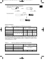
For connecting the LNB’s to the multi-switch and to the components, it is recommended to use of multiple coax- 4 or 5 in a common cable jacket, e.g. MULTIMEDIACable (Art. -No. 0001/3014)
For connecting the multi-switch to the antenna sockets, the use of Mini-Coax-Cable
(Art. -No. 0001/3011) is recommended.
Due to the amplification provided by the units, you can use thin, flexible, easily handled cable types even with higher loss.
To install long stretches of cable connections to the antenna sockets, please use
the low-loss coaxial cable CoaxSat 2150 (Art. -Nr 0002/3107) or (Art. -Nr 0001/3106).
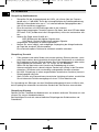
For professional appliance, TechniSat recommends not to use F-connectors that need
to be screwed on to the cable. For the home use you can apply above described
connectors, if professional crimping tools are not available.
Buy cables and connectors at your specialist dealer. They are able to provide cut cables in
quantity and can assist you with your questions!
Regarding connectors and cutting lengths refer to chapter 5.1
4.3 Antenna sockets
Participants can be connected to the system using TechniPro SV 500
(3-pin antenna sockets, Art. -Nr 0000/3075). This facilitates reception of terrestrial programs
with no need for connections to be changed, and the equipment is protected from interference from other bands.
5 Installation of large-scale GigaSystem-distributions
Distribution installations for SMA and CATV (respectively terrestrial) signals) involving more
than 40 participants should only be installed by professionals with an appropriate level of
knowledge on interdependent parameters, and who have a selective antenna measuring and
calibration unit available.
Large-scale installations are set up in a multiple trunk – star-shaped structure.
A large number of sub-distributions can be supplied by a main trunk line. This is necessary to
ensure the insulation does not deteriorate to a level where the system becomes unusable
(20dB, incl. Frequency response- and neighbouring reserves).
A few brief notes on functions, by way of explanation:
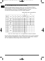
In the switching matrices, the signal is acquired by directional couplers, and then transported
to the individual participant by means of MMIC switches via filters and amplifiers. Although
this path ensures there is no loss of signal strength (damping) caused by the switching matrices, the level within the switching matrix is significantly lower in some sections. Therefore the
input level of the switching matrix should not be less than 58dBμV.
As the trunk lines present a high level of decoupling, you can practically eliminate any interference based on lack of insulation, as long as you follow the notes presented in this chapter.
29
GB
4.2 Cables and connectors