1
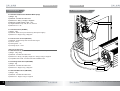
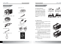
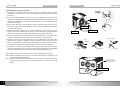
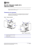
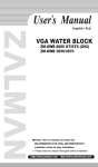
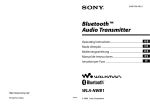
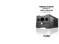
English Version
RESERATOR XT
RESERATOR XT
Installation and Operational Notes
Installation Notes
English
English Version
1. Do not place the unit in dusty or humid conditions, under direct sunlight, or near a heat
source such as a room heater.
2. Do not drop or subject the unit to excessive force.
3. Check the CPU socket compatibility before installation.
4. Do not mix any contaminants with the coolant when filling. It may cause product failure
or corrosion.
5. Place the unit on top of the PC or a location with good ventilation.
6. Check for leaks on the Water Blocks and Tubes before installation.
7. Preparing the necessary tools (Needle-Nose Pliers, Scissors) will ease the installation
process.
Operational Notes
1. Check to see if the DC cables are properly connected before use.
2. If the coolant is not circulating properly or if the pump’s flow rate becomes too low for
other reasons, then the red LED will begin to flicker with an alarm sound. Immediately
turn the PC OFF and contact the place of purchase.
3. Do not place any objects on the product.
4. Install the unit on a leveled surface free of vibration, and do not tilt or lay the unit on its
side while using.
5. Must use the provided coolant. Regularly check the amount of coolant and replenish
as needed (must be with new coolant every year).
6. If a leak is found, turn off the system immediately and contact the place of purchase.
7. Separate the Reserator from the PC case when moving the system.
8. Do not block the Air Ducts on either side of the product with any object. It could lead to
fan failure, increased noise, or a decrease in product performance.
9. Make sure that the Water Pump is functioning properly.
Visit our website (www.zalman.co.kr) and watch the Reserator XT
installation video for an installation overview.
※ Please read this manual thoroughly before installation.
※ The specifications of this product and its components may change without
prior notice to improve performance.
1
•The specifications of this product and its components may change without prior notice to improve performance.
Disclaimer
Zalman Tech Co., Ltd. is not responsible for any damages due to external causes,
including but not limited to, improper use, problems with electrical power, accident,
neglect, alteration, repair, improper installation, or improper testing.
•The specifications of this product and its components may change without prior notice to improve performance.
2
RESERATOR XT
Table of Contents
Installation and Operational Notes
1. Features
•High Performance Ultra Quiet Water Cooling System
•Active/Passive Hybrid Cooling Design
- Active Cooling: 140mm Fan (Forced Convection Cooling)
- Passive Cooling: Anodized Aluminum Heatsink Chassis(Natural Convection Cooling)
•Automatic/Manual Control Modes
- Automatic Mode: Coolant Temperature is monitored for Automatic Control of Fan
Speed and Coolant Flow Rate.
- Manual Mode: Front Panel Control Knob allows the user to manually optimize
performance and minimize noise
•Warning & Alarm System
- Coolant Flow Monitoring: Warns the user when coolant flow is problematic.
- Coolant Level Monitoring: Warns the user when the coolant level is low.
•Comprehensive Visual Monitoring Display
- Coolant Temperature (viewable in ℃ or ℉)
- Ambient Temperature (viewable in ℃ or ℉)
- Coolant Level Warning Icon (Lights Up When Coolant Level Is Low)
•Coolant Flow Rate
- Coolant Flow Indicator
- Light Switch
•Automatic Power ON/OFF In Sync with the Computer
•Quick Couplings for Fast, Convenient, and Leak-Free Installation & Maintenance
3
•The specifications of this product and its components may change without prior notice to improve performance.
1) CPU Water Block (ZM-WB5)
The CPU Water Block incorporates a pure copper base for
excellent heat transfer. The Water Block Cover has been anodized
to prevent corrosion. It supports Intel’s Socket 775 CPUs and
AMD’s Socket 754/939/940/AM2 CPUs, and is designed to be light
weight and easy to install.
English
1. Features ………………………………………………………………………………………3
2. Specifications …………………………………………………………………………………5
3. Installation Overview …………………………………………………………………………6
4. Components …………………………………………………………………………………7
5. Installation Guide ……………………………………………………………………………8
6. Optional Products …………………………………………………………………………17
RESERATOR XT
2) Anti-Corrosion Coolant (ZM-G300)
This coolant contains a high quality anti-corrosion agent for various
materials including copper, aluminum, plastic, and other metals that
prevents corrosion for long term operation.
3) FND(Flexible Numeric Display)
Displays the internal temperature, water temperature, water level,
and mode. The black background and wine color details intensify
the aesthetics.
4) Analog Gauge
Displays the fan speed and pump’s flow rate. The wine colored
lighting adds a touch of elegance and tuning effect.
5) Automatic Control
The internal coolant temperature sensor automatically regulates
the fan speed and coolant flow rate for optimal cooling and ultra
quiet operation.
6) Flow Indicator
This component is connected with the circulation tube for checking
the circulation of the coolant. When the coolant is circulating
properly, its impeller rotates to visually indicate the status of
coolant flow.
7) Quick Coupling
The Fittings incorporate valves that prevent leaks when
disassembling the Reserator, allowing quick and convenient
separation and reassembly of the Reserator for transport and
coolant replacement.
•The specifications of this product and its components may change without prior notice to improve performance.
4
RESERATOR XT
2. Specifications
RESERATOR XT
3. Installation Overview
English
2.1 Reserator XT (Reservoir+Radiator+Water pump)
1) Weight : 7kg
2) Materials : Anodized Pure Aluminum
3) Dimensions : 350(L) x 210(W) x 180(H)mm
4) Maximum Coolant Capacity : Max. 1.25ℓ
5) Integrated Water Pump : 6W, DC 12V, 300L/Hr
6) Maximum Lift : 1.8m
CPU WATER BLOCK
2.2 CPU Water Block (ZM-WB5)
1) Weight : 160g
2) Materials : Base Cover (Pure Aluminum), Base (Pure Copper)
3) Dimensions : 63(W) x 63(L) x 40(H)mm
2.3 Anti-Corrosion Coolant (ZM-G300)
1) Materials : Propylene Glycol & Anti-Corrosion Agent
2) Volume : 250㎖
3) Freezing Point : -9℃
4) Exchange Cycle : 1Year
<Optional Components>
2.4 VGA Water Block (ZM-GWB3 / GWB8800 Ultra & GTX / GTS)
1) Weight : 100g / 420g
2) Materials : Anodized Pure Aluminum
3) Dimensions : 60.4(L) x 60.4(W) x 30(H) mm / 183(w) x 95(L) x 30(H)mm
4) Compatible VGA Cards : All VGA cards with installation holes
2.5 Northbridge Water Block (ZM-NWB1)
1) Weight : 48g
2) Materials : Anodized Pure Aluminum
3) Dimensions : 43(W) x 43(L) x 30(H)mm
2.6 VGA RAM Water Block (ZM-RWB1)
1) Weight : 120g
2) Materials : Anodized Pure Aluminum
3) Dimensions : 19(W) x 122(L) x 12(H)mm
5
•The specifications of this product and its components may change without prior notice to improve performance.
IN Terminal
DC Power
OUT Terminal
•The specifications of this product and its components may change without prior notice to improve performance.
6
RESERATOR XT
5. Installation Guide
4. Components
1) Reserator XT- 1 Unit
RESERATOR XT
6) PVC Tube - 4m
2) CPU Water Block (ZM-WB5) - 1SET
English
7) I/O Bracket - 1EA
5.1 Reserator Placement
The Reserator’s placement
should be determined in relation
to the position of the PC. Place it
upright, next to or slightly above
the PC. Note that if the Reserator
is placed lower than the PC, the
PVC Tube’s internal air pressure
may prevent proper initial
operation.
8) Degassing Tube - 1EA
3) DC Cable - 1EA
9) Tube Clamp - 2EA
4) Jump Cable - 1EA
10) User’s Manual - 1EA
5) Coolant (ZM-G300) - 1EA
7
•The specifications of this product and its components may change without prior notice to improve performance.
5.2 Adding Coolant
1) Remove the Reserator XT’s Reservoir Cap by
turning it counter-clockwise.
2) Mix the provided coolant with one liter of distilled
water in a bowl.
3) The entry hole is small. Therefore, use the
provided coolant container to fill the Reserator
with mixed coolant (four separate pours for a
sum of 1000㎖).
Note 1) Fill by four separate pours to prevent overflowing
of coolant. Once air has been completely
released and the coolant begins to circulate, then
refill the remaining coolant (250㎖).
Note 2) The provided coolant is a concentrated liquid.
Therefore, it must be diluted with distilled water in
a 1:4 ratio.
Note 3) Read the warning label on the coolant before
use.
Note 4) Keep this product and its associated system
away from children.
•The specifications of this product and its components may change without prior notice to improve performance.
8
RESERATOR XT
PUSH
English
5.3 Reserator XT’
s Coolant Circulation
1) The purpose of connecting the Jump Cable of the Power Supply’s Main Connector
(20P/24P) is to receive direct current (12V) needed for the test run and leakage
inspection.
2) For smooth initial degassing, connect one end of the Degassing Tube to the OUT
terminal of the Reserator, and repeatedly press the opposite Quick Coupling end - with
the finger to discharge the internal air. Now remove this end of the Degassing Tube
from the OUT terminal.
3) Connect the other end of the Degassing Tube to the IN terminal and remove the
internal air in the method described above, and connect the opposite Quick Coupling
end to the OUT terminal.
4) Remove the Power Supply’s Main Connector (20P/24P) and the 4-Pin CPU Sub
Connector from the motherboard, and connect the Green Wire Terminal and Black
Wire Terminal of the Main Connector (20P/24P) with the provided Jump Cable.
5) Connect the DC Cable to the Power Terminal on the Reserator XT’s back panel, and
connect the opposite 4-Pin Connector to the Power Supply’s 4-Pin Connector.
6) Supplying power to the Power Supply will light up the Red LED on the front panel,
cause the Flow Indicator’s Impeller to rotate, and the Blue LED on the side panel to
light up. For discharging of the gas within the Reserator and good coolant circulation,
turn the Power Supply ON/OFF approximately 3~7 times in 10 second intervals.
7) Circulate the coolant for approximately 10 minutes for leakage inspection and for
checking its operation, then turn OFF the Power Supply. Disconnect the Degassing
Tube, and disassemble the Quick Coupling Inserts from the Degassing Tube.
RESERATOR XT
DC Cable
OUT Terminal
Degassing Tube
IN Terminal
4-Pin Connector
Main
Connector
M/Board
Jump Cable
Note 1) Make sure that the coolant of the Reservoir does not overflow when tilting the unit.
Note 2) Check the degassing status by looking at the tubes. Once degassing is complete, turn the
PC OFF and install the Water Blocks.
Note 3) If the Flow Indicator detects a problem with coolant circulation, an alarm will sound and the
red LED will begin to flicker. Press the Light/Reset button for 5 seconds to restart the
system.
DC Cable
Flow indicator
LED/Reset Button
9
•The specifications of this product and its components may change without prior notice to improve performance.
•The specifications of this product and its components may change without prior notice to improve performance.
10
RESERATOR XT
5.4 CPU Water Block Installation (ZM-WB5)
1) Refer to the manual provided with the ZM-WB5 for installation.
2) If interference occurs while installing the Water Block, then stop the installation.
5.7 DC Power Cable Connection
1) Fit the DC Cable’s Cord Bushing into the groove of the I/O Bracket, and fasten the I/O
Bracket with a Bolt.
2) Connect the DC Cable Connector to the 4-Pin Connector of the Power Supply.
Note 1) Do not exert excessive force when connecting the connector. Slowly connect with both
hands.
Cord Bushing
4-Pin Connector
Bolt
English
5.5 CPU Water Block and Reserator’
s Base IN Connection
1) Connect one end of the PVC Tube to the Fitting of the CPU Water Block and fasten
with a Tube Clamp as shown in the diagram.
2) Pull out the PVC Tube through the I/O Bracket hole on the computer case.
3) Connect the Quick Coupling Insert that has been disconnected from the Degassing
Tube to the other end of the PVC Tube, and fasten it with Tube Clamp.
4) Plug the Quick Coupling Insert into the Quick Coupling Socket of the Base IN fitting.
RESERATOR XT
DC Cable Connector
I/O Bracket Bolt
Base IN, Quick Coupling Body
5.6 CPU Water Block and Reserator’s Base OUT Connection
1) Connect one end of the PVC Tube to the CPU Water Block Fitting and fasten with a
Tube Clamp as shown in the diagram.
2) Pull out the PVC Tube through the tube hole of the I/O Bracket.
3) Connect the Quick Coupling Insert to the other end of the PVC Tube, and fasten with a
Tube Clamp.
4) Plug the Quick Coupling Insert into the Quick Coupling Socket of the Base OUT fitting.
Base OUT, Quick Coupling Body
11
•The specifications of this product and its components may change without prior notice to improve performance.
<Installation of Optional Products>
◈ VGA Water Block Installation
Connect the CPU Water Block and the VGA Water
Block with the PVC Tube and fasten them with Tube
Clamps as shown in the diagram.
Note 1) Using Needle-Nose Pliers for fixing the Tube
Clamps in place will make the installation easier.
PVC Tube
VGA
Water Block
- VGA Water Block and Reserator’s Base IN Connection
1) Connect one end of the PVC Tube to the Fitting of the VGA Water Block and fasten
with a Tube Clamp as shown in the diagram.
2) Pull out the PVC Tube through the I/O Bracket hole on the computer case.
3) Connect the Quick Coupling Insert that has been disconnected from the Degassing
Tube to the other end of the PVC Tube, and fasten it with a Tube Clamp.
4) Plug the Quick Coupling Insert into the Quick Coupling Socket of the Base IN fitting.
I/O Bracket
Base IN, Quick
Coupling Body
•The specifications of this product and its components may change without prior notice to improve performance.
12
RESERATOR XT
5.8 Confirmation of Proper Installation
1) Check if the product is placed properly.
2) Check if the coolant’s circulation path conforms to the path shown below.
3) Slightly tug on the PVC Tubes connected to each Fitting to check for loose
connections.
Reserator OUT
CPU Water Block
English
- CPU Water Block and Reserator’s Base OUT Connection
1) Connect one end of the PVC Tube to the Fitting of the CPU Water Block and fasten
with a Tube Clamp as shown in the diagram.
2) Pull out the PVC Tube through the I/O Bracket hole on the computer case.
3) Connect the Quick Coupling Insert that has been disconnected from the Degassing
Tube to the other end of the PVC Tube, and fasten it with a Tube Clamp.
4) Plug the Quick Coupling Insert into the Quick Coupling Socket of the Base OUT fitting.
RESERATOR XT
N/B Water Block
<OPTION>
Reserator XT body
Radiate
Heat
Absorb
Heat
Quick Coupling Insert
◈ Northbridge Water Block Installation
1) When using the Northbridge Water Block, please install as illustrated below.
2) The Tube Clamps must be installed on the PVC Tubes.
CPU Water Block
Tube Clamp
Northbridge Water Block
VGA Water Block
- VGA RAM Water Block Installing
1) When using the VGA RAM Water
Block, please install as illustrated in
the diagram.
2) The Tube Clamps must be installed
on the PVC Tubes.
CPU Water Block
VGA RAM
Water Block
VGA Water Block
13
•The specifications of this product and its components may change without prior notice to improve performance.
Reserator IN
VGA Water Block
<OPTION>
RAM Water Block
<OPTION>
5. 9 Leakage Inspection and Test Run
1) Check to see if the green wire terminal and the black wire terminal of the Power
Supply’s Main Connector are connected with the Jump Cable.
2) Check the amount of coolant inside the Reserator’s Reservoir, and fill it by
approximately 80%.
3) Connect the Power Supply’s 4-Pin Connector to the Reserator’s DC Cable
Connector, and provide power for the Power Supply.
4) Once power is supplied, check to see if the Flow Indicator’s impeller placed inside the
Reserator’s side panel is rotating, if the blue LED is lit, and if the coolant is being
circulated to each Water Block.
5) Check for leakage at each connector. Leakage can lead to short-circuits and damage
the motherboard or other components. If leakage is found, turn OFF the power,
completely remove the water, and reassemble the leaking section.
6) If there is no leakage, remove the Power Jump Cable from the Power Supply’s Main
Connector. Now connect the Power Supply’s Main Connector to the motherboard’s
Power Connector and run the PC.
Note 1) Power must be supplied to the Reserator’s DC Cable at all times for the Reserator and the
PC to run simultaneously. The user must check periodically to see if the DC Cable is
connected properly.
•The specifications of this product and its components may change without prior notice to improve performance.
14
RESERATOR XT
5.10 Front Panel Display
②
④
⑤
15
⑥
⑦
•The specifications of this product and its components may change without prior notice to improve performance.
③
◈ Front Panel Display
① Fan Speed Gage
- Displays the Fan Speed(rpm). If there is a problem, the display will flicker. If the
flickering is observed, please check if there are any mechanical or pump related
problems.
② FND(Flexible Numeric Display) Display
- Temperature Display
Coolant Temperature(upper display)
Ambient Temperature(lower display)
- Coolant Level Sensing
If a certain quantity of coolant is unavailable, an alarm will sound and the display will
flicker. If the flickering is observed, please refill with coolant.
- Coolant Temperature Sensing
If the coolant’s temperature reaches 60℃(92℉) and above, an alarm will sound and
the FND Display will flicker. If the flickering is observed, please check if there are any
problems.
③ Coolant Flow Rate Gage
- Displays the coolant flow rate. If there is a problem, the display will flicker. If the
flickering is observed, please check if there are any mechanical or pump related
problems.
English
①
RESERATOR XT
◈ Control Knob & Buttons
④ Control Knob
- Controls the Fan Speed(rpm) and Coolant Flow Rate.
⑤ ℃/℉ Button
- Sets the temperature display to Celsius(℃) or Fahrenheit(℉).
⑥ AUTO/MANUAL Button
- AUTO Mode: Automatically adjusts fan speed and coolant flow rate.
- MANUAL Mode: Allows the user to manually adjust fan speed and coolant flow rate.
⑦ LED/RESET Button
- LED On/Off: Short pressing of the button turns the displays’LEDs On & Off.
- RESET: Pressing the button for at least 5 seconds will reset the Reserator XT.
•The specifications of this product and its components may change without prior notice to improve performance.
16
RESERATOR XT
Zalman Noise Prevention System
Stable performance and noiseless liquid cooling system can both be achieved with the
use of Zalman’s Noiselee Power Supply, VGA Water Block, Northbridge Water Block,
VGA RAM Water Block.
Noiseless
Power Supply
VGA Water block
Northbridge
Water Block
VGA RAM Water Block
Heatpipe Cooled Modular Power Supply
ZM500-HP
ZM600-HP
- Reduction in the PFC circuitry’s switching FET heat generation by use of 3
Parallel switching FETs (normally 1 or 2 used)
- Heatpipe cooling system on the main rectifier (output) diodes for maximum stability and
minimum fan speed for ultra quiet operation
- Modular design for convenient and tidy cable installation
- Blue LEDs for cool aethetics
Gaming PC Enclosures
GT 1000
17
- High end Gaming Enclosure built sturdy all
aluminum aanels
- Three tool free hinged magnetic panel(2 Left, 1
Right) for easy installation and access to components
- Tool free installation of disk drives, Fan
Controllers, Audio interfaces etc
- Accommodates up to 6 Hard Drives
- Luxurious and cool aesthetics
- Color option: Black (Red LED Fans), Titanium
(Blue LED Panel)
For more information, please visit our website.
•The specifications of this product and its components may change without prior notice to improve performance.