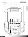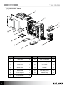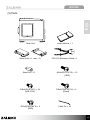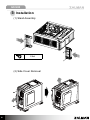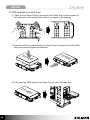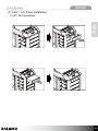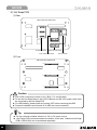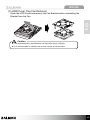
1
English
GS1200
1 Cautionary Notes
1) Please read this manual thoroughly prior to installation.
3) Avoid inserting objects or hands into the system while it is in
operation to prevent product damage and injuries.
Eng
2) Before installing, check the components and condition of the
product, and if any problem is found, contact the retailer.
4) Check the manual when connecting cables. Incorrect connections
may cause short circuits leading to fire hazards.
5) Do not block the Front Intake Vent or the Rear Exhaust Vent.
6) Keep this unit away from heat sources, direct sunlight, water,
oil, and humid environments, and place the unit on a flat, stable,
vibration-free, and well-ventilated area.
7) Do not clean the product surface with chemicals or wet cloth.
(chemicals: industrial brightener, wax, benzene, alcohol, paint
thinner, mosquito repellent, aromatics, lubricant, detergent etc.)
8) Please wear gloves while handling this product to prevent injuries.
9) Product design and specifications may be revised to improve quality
and performance.
Disclaimer) Zalman Tech Co., Ltd. is not responsible for any damages due to
external causes, including but not limited to, improper use, problems
with electrical power, accident, neglect, alteration, repair, improper
installation, or improper testing.
1
GS1200
2 Product Details
(1) Specifications
Models
GS1200
Type
Full Tower
Dimensions (W×H×D)
260 × 570 × 640㎜ (10.2” × 22.4” × 25.1”)
Weight
12.4㎏
Materials
Plastic, Steel and Aluminum
Color
Black
Compatible Motherboards
Standard ATX / m-ATX / E-ATX
Compatible PSU’s
Standard ATX / ATX12V
Compatible VGA Cards
Full Size(350㎜)
5.25” Bay
4
3.5” Bay
Cooling
Components
Internal
6
External
1
Front
92㎜ LED Fan × 2
Rear
120㎜ Fan × 1
Top
200㎜ LED Fan × 1
Side
200㎜ LED Fan × 1
Mic × 1, Headphone × 1, USB 2.0 × 3,
Top Panel
e-SATA × 1, USB 3.0 × 1
Supports Hot Swap
SATA Ⅰ / SATA Ⅱ
(2) Product Information
Front
2
Top
Side (left)
GS1200
(3) Top Panel I/O Ports and HDD Docking Station
Eng
HDD Docking Station
USB 2.0
USB 3.0
e-SATA
USB
RESET
Power LED
Reset Button
USB
e-SATA
MIC
Mic
HEADPHONE
Headphones
USB
USB
POWER
HDD LED
Power Button
3
GS1200
(4) Exploded View
⑩
⑪
⑫
⑬
⑨
⑧
⑦
③
⑥
②
①
⑤
④
4
#
Part Name
Units
#
Part Name
Units
①
HDD Tray
6
⑧
Side Cover (right)
1
②
HDD Tray Cover
2
⑨
Side Cover (left)
1
③
Front Cover
1
⑩
Top Cover
1
④
Stand (front)
1
⑪
Chassis
1
⑤
Stand (rear)
1
⑫
5.25” Bay Cover
3
⑥
PSU Support
1
⑬
Adapter Tray
1
⑦
PSU Bracket
1
GS1200
(5) Parts
Eng
Main Unit
Stand (front ×1, rear ×1)
Stand-Off × 11
B Bolt(PH 6-32*6) × 24
[M/B, PSU]
D Bolt(PWH M3*6) × 4
[SSD]
User’s Manual × 1
CPU 12V Extension Cable × 1
A Bolt(PH 6-32*12) × 12
[HDD]
C Bolt(PWH M3*12) × 4
[Stand]
Cable Tie × 10
5
GS1200
3 Installation
(1) Stand Assembly
C Bolt
(2) Side Cover Removal
6
GS1200
(3) PSU Installation
Eng
Or
Type A
Type B
B Bolt
Type A
Type B
Tip
▶ Type A (PSU independent cooling)
If the PSU’s fan points downwards, the PSU’s cooling performance is
enhanced.
▶ Type B (Case Air Circulation Type)
If the PSU’s fan points inwards, the PSU’s cooling performance is
enhanced.
※ When using the case in a dusty environment, use Type B.
7
GS1200
(4) Motherboard Installation
Please refer to the diagrams below for additional Stand Off positions (based
on motherboard type).
ATX Board
m - ATX Board
Stand-Off
B Bolt
8
GS1200
(5) VGA Card Installation
Eng
(6) Hot Swap HDD Installation
1) HDD Tray Removal
1
2
1
9
GS1200
2) HDD Installation (to HDD Tray)
① ‘Open’ the Hot Swap Tray by pressing the Hot Swap Tray’s Hooks located on
the underside, and pushing in the direction as shown in the diagram.
② Install the HDD and check that the Hot Swap Tray’s Fixing Pins and the HDD’s
holes are properly aligned and fastened.
3.
D
D
H
D
D
H
5”
5”
3.
③ Fully insert the HDD installed Hot Swap Tray into the Hot Swap Bay.
D
D
”H
5
3.
D
D
H
5”
3.
10
GS1200
(7) 5.25” / 3.5” Drive Installation
1) 5.25” ODD Installation
Eng
11
GS1200
2) Adapter Tray Installation
① Adapter Tray Removal
② Drive Installation to Adapter Tray
A. 3.5” FDD Installation
D Bolt
5”
3.
D
FD
5”
3.
D
FD
B. 3.5” HDD Installation
B Bolt
5”
3.
5”
3.
D
D
H
D
D
H
12
GS1200
C. 2.5” SSD Installation
D나사
Eng
D
SS
D
SS
3) Top HDD Docking Station
① 3.5” HDD Installation
② 2.5” HDD Installation
13
GS1200
5) Hot Swap PCB
① Rear
ZM-HS100 HOT SWAP PCB
A
HIGH
B
LOW
C
S-ATA Connector
3-Pin Fan Connector
4-Pin Power Connector
Fan Controller
② Front
ZM-HS100 HOT SWAP PCB
a
b
c
Caution
▶ The S-ATA connectors connect in A=a / B=b / C=c configuration.
▶ To use the Hot-Swap feature, the S-ATA Cable(s) and the 4-Pin power cable must
be connected to the Hot-Swap PCB.
▶ For HDD stability, please power the system OFF before removing the HDD.
▶ Frequent installation and removal of an HDD can wear connectors.
Tip
▶ The fan controller enables selection of 12V or 5V power source.
▶ 1 Hot Swap PCB comes standard at the bottom of the case. Additional Hot Swap
PCB’s (ZM HS100) can be purchased separately.
14
GS1200
(8) Cable Connection
1) Power Button and LED Cable
Power Button Side
Eng
or
Power LED
Power
Reset
HDD LED
Motherboard side
2) Top Panel I/O Port Cable
Top Panel I/O Port side
Audio
HD Audio
AC ’97
USB 2.0
USB 3.0
e-SATA
Motherboard side
Tip
▶ To connect USB 2.0, 3.0, 3-SATA and audio cables, please refer to the
motherboard manual.
▶ When the +/- polarities are reversed, the LED’s will not function.
15
GS1200
4 Optional Fan Installation and Replacement
(1) Side Cover Fan (200㎜ - standard / 120㎜ - optional)
200㎜ Fan Pre-installed
(standard)
2 x 120㎜ Fan Installation
(optional)
(2) Bottom Panel Optional Fan (120㎜)
16
GS1200
(3) HDD Cover Tray Fan Removal
Open the HDD Cover and remove the Fan Bracket before uninstalling the
Bracket from the Fan.
Eng
Caution
▶ The replaceable fan’s specifications are 92㎜(W) x 92㎜(L) 25㎜(H).
▶ It is recommended to install the fan so that it sucks air into the case.
17