1
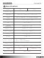
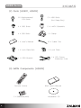
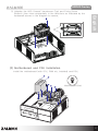
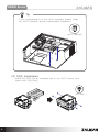
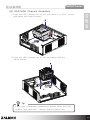
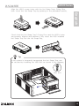
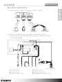
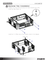
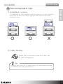
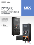
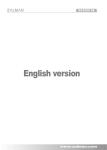
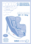
English
HD500 Series
1 Cautionary Notes
(2) Before installing, check the components and condition of the product, and
if any problem is found, contact the retailer.
(3) Avoid inserting objects or hands into the system while it is in operation to
prevent product damage and injuries.
English
(1) Please read this manual thoroughly prior to installation.
(4) Check the manual when connecting cables. Incorrect connections may
cause short circuits leading to fire hazards.
(5) Do not block the Front Intake Vent or the Rear Exhaust Vent.
(6) Keep this unit away from heat sources, direct sunlight, water, oil, and
humid environments, and place the unit on a flat, stable, vibration-free,
and well-ventilated area.
(7) Do not clean the product surface with chemicals or wet cloth. (chemicals:
industrial brightener, wax, benzene, alcohol, paint thinner, mosquito
repellent, aromatics, lubricant, detergent etc.)
(8)Please wear gloves while handling this product to prevent injuries.
(9)Product design and specifications may be revised to improve quality and
performance.
Disclaimer) Zalman Tech Co., Ltd. is not responsible for any damages due to
external causes, including but not limited to, improper use, problems
with electrical power, accident, neglect, alteration, repair, improper
installation, or improper testing.
The diagrams used in this manual are based on model HD503. Installation for
the HD501 follows the exact installation procedure.
1
HD500 Series
2 Specifications
Mo dels
HD503
Enclosure Type
HTPC
Dimensions
(W×H×D)
450 × 170 × 455mm (17.6” X 6.8” X 17.9”)
Weight
Main Unit: 8kg(17.6lb) / with packaging: 9.6kg(21lb)
Materials
Aluminum / Plastic / Steel
Color
Black / Silver
Compatible
Motherboards
Standard ATX / mATX
Compatible PSUs
Standard ATX / ATX12V
PCI/AGP Compatibility
Full Size (Up to 260mm)
5.25” Bays
2 (Hot Swap Bay × 1)
3.5” Bays
3 (SSD × 2)
Cooling Components
Rear: 2 X 80mm fans
Side: 2 X 120mm fans(Optional)
Expansion Slots
7
Front I/O Ports
1 X Mic, 1 X Headphones, 2 X USB, 1 X e-SATA
Display
Supports Hot Swap
2
HD501
N/A
DFSTN LCD
SATA I, SATA II
HD500 Series
English
3 Components
(1) Main Unit
Top Panel
HD501
ODD Chassis
HDD Chassis
Main Chassis
HD503
Top Panel
ODD Chassis
HDD Chassis
Main Chassis
3
HD500 Series
(2) Parts [HD501, HD503]
13 X M
otherboard/
PSU Bolts
2 X H
DD Bolts
(Hot Swap Bay)
4 X ODD Bolts
2 × mATX Standoffs
4 X SSD Bolts
1 X Clamp
1 X User’s Manual
10 X Cable Ties
1 X Lock Plate Bolt
1 X Lock Plate
1 × SSD Bracket
1 × C
PU Power
Extension Cord
(3) iMON Components [HD503]
Remote Control
2 X Batteries(AAA)
4
iMon User’s Manual
Installation CD
HD500 Series
4 Front Panel Components
⑦
English
HD501
⑥
①
⑤
②
①
②
③
④
③
④
Power Button
Power LED
Reset Button
HDD LED
⑤ Front I/O Port
⑥ HDD Hot Swap Bay
⑦ 5.25” ODD Bay
HD503
⑩
①
⑨
②
⑧
③
①
②
③
④
⑤
④
⑤
⑥
LCD & IR Receiver
Power Button
Power LED
Reset Button
HDD LED
⑦
⑥
⑦
⑧
⑨
⑩
Media Control Button
Volume Control Knob
Front I/O Port
HDD Hot Swap Bay
5.25” ODD Bay
5
HD500 Series
5 Installation
(1) Installation Preparation
1) Unfasten the rear screws and remove the Top Panel.
1
2
2) U
nfasten the two screws (Top and Side) holding the ODD
Chassis. With the Side Button pressed, push the ODD Chassis
towards the rear to remove.
SH
PU
6
HD500 Series
English
3) U
nfasten the HDD Chassis’ Handscrew (Top) and Fixing Screw
(Bottom) ,then move sequentially in the directions as indicated by the
numbered arrows in the diagram to remove.
2
1
(2) Motherboard and PSU Installation
PS
U
Install the motherboard (with CPU, RAM etc. installed) and PSU.
Motherboard Bolt
7
HD500 Series
Tip
If the motherboard is of the mATX standard, please install
the mATX Standoffs before motherboard installation.
mATX Standoff
(3) ODD Installation
Install the ODD into an available slot in the ODD Chassis and
fasten with ODD Bolts.
D
OD
8
ODD Bolt
HD500 Series
(4) 3.5” HDD Installation
Use the Hand Screws to
attach the Handle to the
HDD.
English
To remove Handle, pull upwards while pressing the Hook Button.
Push the HDD into the slot
until there is a “Click” sound.
D
HD
HDD
Tip
▶ H
DD removal is possible without removing the HDD Chassis
from the main unit.
▶ P
lease properly align the HDD and HDD Handle during
installation and assembly.
9
HD500 Series
(5) SSD or 2.5” HDD Installation
Insert the SSD in the SSD Bracket and fasten with SSD
Bolts. Reattach the HDD handle to the SSD Bracket.
SSD Bolt
SSD
SSD
Push the SSD into the slot until there is a “Click” sound.
Tip
Two SSD’s can be installed
on a single Bracket.
D
SS
Caution
Installing HDD’s to the bottom
rung can cause short circuiting
so please make sure to install
HDD’s to the top rung.
10
HD500 Series
(6) ODD/HDD Chassis Assembly
1
English
1) P
ush the ODD Chassis into its slot until there is a “Click” sound
and fasten with Hand Screws.
2
2) P
ush the HDD Chassis into its slot and fasten with the
Hand Screws.
1
2
Tip
If the case is frequently transported, please fasten the ODD
Chassis (Top) and HDD Chassis (Bottom) before use.
11
HD500 Series
(7) Hot Swap Bay Installation
1) HDD Tray Removal
Push the Hot Swap Bay Cover to open.
SH
PU
While squeezing and holding the Hot Swap Tray’s Hook in ‘Direction 1’,
pull in ‘Direction 2’ to remove the Hot Swap Tray.
1
1
2
2) 3.5” HDD Installation
‘Open’ the Hot Swap Tray by pressing the Hot Swap Tray’s
Hooks located on the underside, and pushing in the direction as
shown the diagram.
12
HD500 Series
Align the HDD’s screw holes with the Hot Swap Trays Fixing Pins,
then ‘close’ the Hot Swap Tray by pushing in the protruded section.
English
D
D
H
D
D
H
Check that the Hot Swap Tray’s Fixing Pins and the HDD’s holes
are properly aligned and fastened. Fully insert the HDD installed
Hot Swap Tray into the Hot Swap Bay.
D
HD
D
D
H
Tip
If the system is frequently transported the Hot Swap Tray can
be secured by installing the HDD Bolt as shown in the diagram.
HDD Bolt
13
HD500 Series
3) Hot Swap Cable Connection
<Hot Swap PCB Front>
<Hot Swap PCB Rear>
4 Pin Power Port (HDD)
S-ATA Port
4-Pin Power Port (Fan)
3-Pin Fan
Connector
Fan Speed Control Switch
(Up: 12V/ Down: 5V)
The S-ATA cable and power cable MUST be connected to the
S-ATA Port AND 4-Pin Power Port before powering ON.
Warning
For stable operation, please turn the system OFF before
HDD removal.
14
HD500 Series
(8) Cable Connections
English
1) Front Panel I/O Cable Connections [HD501, HD503]
e-SATA
USB
HD Audio
AC’97 Audio
2) DFSTN and Media Controller Cable Connections [HD503]
Please refer to the motherboard’s manual for cable connections
to the motherboard.
DFSTN PCB
PSU
⑥
}
①
②
③
④
⑤
Motherboard Power
① USB(4/5-Pin)
④ Reset(2-Pin)
② Power(2-Pin)
⑤ HDD LED(2-Pin)
③ Power LED(2/3-Pin)
⑥ Standby Power(20/24-Pin)
15
HD500 Series
6 Optional Fan Installation
Unfasten the Fixing Bolts and press the Hooks towards each other
to pull the Side Panels off.
Install the 2 X 120mm fans to the locations shown in the diagram.
Intake Fan
Exhaust Fan
16
HD500 Series
1) Installation Location
For adequate air flow, please install the system in a well ventilated
area. Low air flow can cause high fan RPM, which can create
unwanted noise.
O
O
English
7 Recommended Use
X
2) Cable Routing
Please use the provided Clamp and Cable Ties
for cable management.
Tip
Keeping the case free of cable clutter will allow better air flow
for enhanced cooling performance.
17
HD500 Series
MEMO
18